Panasonic WJ-GXE100 Installation Manual
Network video encoder
Hide thumbs
Also See for WJ-GXE100:
- Specifications (2 pages) ,
- Operating instructions manual (132 pages)
Table of Contents
Advertisement
Quick Links
Installation Guide
Included Installation Instructions
Network Video Encoder
WJ-GXE100
Model No.
WJ-GXE100E
Before attempting to connect or operate this product, please read these
instructions carefully and save this manual for future use.
The model number is abbreviated in some descriptions in this manual.
Advertisement
Table of Contents

Related Manuals for Panasonic WJ-GXE100


Summary of Contents for Panasonic WJ-GXE100
-
Page 1: Installation Guide
Installation Guide Included Installation Instructions Network Video Encoder WJ-GXE100 Model No. WJ-GXE100E Before attempting to connect or operate this product, please read these instructions carefully and save this manual for future use. The model number is abbreviated in some descriptions in this manual. - Page 2 Bestimmungen der Richtlinie 2004/108/EC. For U.S. and Canada: Nous déclarons sous notre propre responsabilité que le WJ-GXE100 produit auquel se réfère la présente déclaration est For Europe and other countries: conforme á la norme spécifiée ou à tout autre document WJ-GXE100E normatif conformément aux dispositions de la directive...
-
Page 3: Table Of Contents
Contents Important safety instructions ......................4 Limitation of liability ........................5 Disclaimer of warranty ........................5 Preface ............................5 Main functions ..........................6 About the user manuals ........................ 6 System requirements for a PC ...................... 7 Trademarks and registered trademarks..................8 Copyright ............................ -
Page 4: Important Safety Instructions
Important safety instructions 1) Read these instructions. 2) Keep these instructions. 3) Heed all warnings. 4) Follow all instructions. 5) Do not use this apparatus near water. 6) Clean only with dry cloth. 7) Do not block any ventilation openings. Install in accordance with the manufacturer's instruc- tions. -
Page 5: Limitation Of Liability
IMPROVEMENTS OF THIS PUBLICATION AND/OR THE CORRESPONDING PRODUCT (S). Disclaimer of warranty IN NO EVENT SHALL Panasonic System Networks Co., Ltd. BE LIABLE TO ANY PARTY OR ANY PERSON, EXCEPT FOR REPLACEMENT OR REASONABLE MAINTENANCE OF THE PRODUCT, FOR THE CASES, INCLUDING BUT NOT LIMITED TO BELOW:... -
Page 6: Main Functions
It is also possible to add other RS485 commands that are not included on the setup menu by uploading command tables. About the user manuals There are 2 sets of operating instructions for the WJ-GXE100 (P model), WJ-GXE100E (E model) as follows. • Installation Guide: Explains how to install and connect devices. -
Page 7: System Requirements For A Pc
• If using Microsoft Windows XP, screen tearing* may occur when the shooting scene drastically changes (for example, while shooting fast-moving subjects) due to the GDI restrictions of the * A phenomenon in which portions of the screen are displayed out of alignment • F or information on the operation verification of the supported operating systems and web browsers, refer to our website at http://panasonic.net/pss/security/support/index.html. -
Page 8: Trademarks And Registered Trademarks
Trademarks and registered trademarks • Adobe, Acrobat Reader, and Reader are either registered trademarks or trademarks of Adobe Systems Incorporated in the United States and/or other countries. • Microsoft, Windows, Windows Vista, Internet Explorer, ActiveX, and DirectX are either regis- tered trademarks or trademarks of Microsoft Corporation in the United States and/or other countries. -
Page 9: Precautions
Precautions Refer installation work to the dealer. Avoid installing this product in the loca- tions where salt damage occurs or corro- Installation work requires technique and experi- sive gas is produced. ences. Failure to observe this may cause fire, Otherwise, the mounting portions will deterio- electric shock, injury, or damage to the prod- rate and accidents such as a fall of this product uct. - Page 10 Avoid placing receptacles that contain liq- To keep on using with stable performance uids such as water near this product. Do not use this product in hot and humid con- ditions for a long time. Failure to observe this If liquid spills onto the unit, it may cause fire or an electric shock.
- Page 11 Transmission interval Image transmission interval may become slow depending on the network environment, PC performance, shooting subject, access num- ber, etc. Code label The code labels (accessory) are required at inquiry for trouble. Use caution not to lose these labels. It is recommended to paste one of the labels onto the CD-ROM case.
-
Page 12: Precautions For Installation
Precautions for Installation Panasonic assumes no responsibility for injuries or property damage resulting from fail- ures arising out of improper installation or operation inconsistent with this documenta- tion. This product is designed to be used • Locations where the temperature is not indoors. - Page 13 Screw tightening For BNC coaxial cable connection • The screws and bolts must be tightened Use only the recommended plug below when with an appropriate tightening torque connecting a BNC coaxial cable (locally pro- according to the material and strength of cured) to the video input connector on the unit.
-
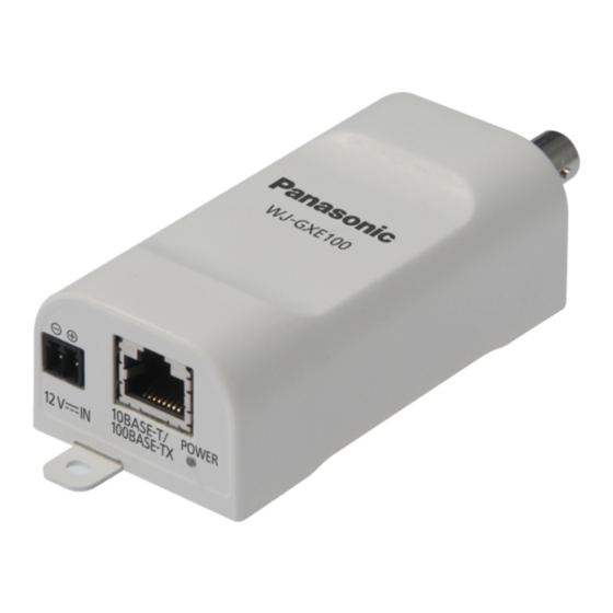
Page 14: Major Operating Controls
Major operating controls 12 V DC power supply terminal Network connector <About the live indicator> When the power is Lights green turned on When connected to a Lights orange network (not accessed) When connected to a Blinks orange/ network (accessed) Blinks green Live indicator INITIAL SET button... - Page 15 Video input connector RS485 port Video Input terminal switch Video Input terminal switch Terminated (default setting) Not terminated...
-
Page 16: Preparations
Preparations The screws used to mount the unit to a wall or ceiling are not supplied. Prepare the screws according to the material, structure, strength and other factors of the mounting area and the total weight of objects to be mounted. IMPORTANT: • Purchase 2 screws (M3) according to the material of the installation area. Nails cannot not be used for mounting. -
Page 17: Mounting To A Wall Or Ceiling
Mounting to a wall or ceiling As necessary, set the terminal resistance (75 Ω) to on or off with the video input terminal switch. (☞ Page 15) Use 2 mounting screws (locally procured) to mount the unit directly to a wall or ceiling. Fix screws to the mounting holes in order from q to w. - Page 18 IMPORTANT: • Take the following cautions to prevent this product from overheating. Failure to observe this may cause fire or trouble. · Do not block the ventilation areas · Mount the unit at least 2 cm {25/32 inches} away from other walls or objects (Mount the unit so that excessive force is not applied to the connected cables when they are con- nected) ·...
-
Page 19: Connection
22 AWG - 28 AWG, Single core, twisted RB RA TB TA * C heck whether the stripped part of the wire is not exposed Receive Transmit and is securely connected. Strip range 9 mm - 10 mm {11/32 inches - 13/32 inches} Signal Signal Twisted-pair cable Receive Transmit Transmit Receive Twisted-pair cable Connected device WJ-GXE100... - Page 20 IMPORTANT: • T he RS485 port of this unit is intended for use with 4-line communications. When connecting 2-line communication devices, make connections as shown in the fol- lowing illustration. Twisted-pair cable (RS485, 2-line) 2-line 4-line • W hen making connections with 2-line communications, select “2-line” in the setup menu. Refer to the Operating Instructions on the provided CD-ROM for further information about the setup menu.
- Page 21 When using 12 V DC power supply* q Loosen the screws of the power cord plug (accessory). w Connect the cable of the 12 V DC power supply* to the power cord plug. Strip the end of the wire by 3 mm - 7 mm {1/8 inches - 9/32 inches}, and twist the stripped part of the wire sufficiently to avoid short circuit.
- Page 22 When using PoE (IEEE802.3af compliant) Connect a LAN cable (category 5 or better, straight, STP*) between a PoE device (such as a hub) and the network connector of the unit. * E model only IMPORTANT: • Use all 4 pairs (8 pins) of the LAN cable. • The maximum cable length is 100 m {328 feet}. • Make sure that the PoE device in use is compliant with IEEE802.3af standard. • When connecting both the 12 V DC power supply and the PoE device for power supply, 12 V DC will be used for power supply. Depending on the PoE device used, the power supply lamp may not light and the network connections may not be possible.
- Page 23 Connection example when connecting to a network using a PoE hub PoE device (hub) LAN cable (category 5 or better, straight, STP*) BNC coaxial cable Analog camera <Required cable> LAN cable (category 5 or better, straight, STP*) * E model only IMPORTANT: • Use a switching hub or a router which is compliant with 10BASE-T/100BASE-TX. • If a PoE device (hub) is not used, the network video encoder must be connected to a power supply.
-
Page 24: Configure The Network Settings
CDLauncher. Click the [Run] button next to [IP Setting Software]. “Panasonic IP Setting Software” page will be displayed. Click the [Network Settings] button after selecting the MAC address/IP address of the unit to be configured. Select the unit you want to configure, and click [Access Camera]. - Page 25 (When the effective period is set to “20 min” in the “Easy IP Setup accommodate period”.) However, settings can be changed after 20 minutes for units in the initial set mode. • “Network Camera Recorder with Viewer Software Lite” which supports live monitoring and recording images from multiple cameras is available. For further information, refer to our website (http://panasonic.net/pss/security/support/info.html).
-
Page 26: Troubleshooting
Troubleshooting Before asking for repairs, check the symptoms with the following table. Contact your dealer if a problem cannot be solved even after checking and trying the solution in the table or a problem is not described below. Reference Cause/solution Symptom pages When using DC power supply... - Page 27 Cameras cannot be are correct. controlled. • If Pan/Tilt/Zoom functions cannot be operated for Panasonic cameras, you must select “Custom” for “Protocol” on the [RS485] tab of the “Image” page and upload the command table to the – unit. For further information, refer to our website (http://panasonic.net/pss/security/...
-
Page 28: Specifications
Unit (metal part): Electrogalvanized steel sheet, sail white coating Encoder • RS485 communication Pan/tilt/zoom/focus/preset positions/auto focus/brightness with cameras: (When using Panasonic combination cameras) Camera control protocol: Panasonic/Pelco-D/Pelco-P/Custom Camera title on screen: Up to 20 characters (alphanumeric characters, marks) On/Off Video motion detection... - Page 29 Resolution PAL mode: Picture (Camera) mode: VGA [4:3] H.264 VGA (640x480)/QVGA (320x240), max. 25 fps JPEG VGA (640x480)/QVGA (320x240), max. 25 fps Picture (Camera) mode: VGA [16:9] H.264 VGA (640x360)/QVGA (320x180), max. 25 fps JPEG VGA (640x360)/QVGA (320x180), max. 25 fps Picture (Camera) mode: H.264 D1 (720x576), max.
- Page 30 (As of December, 2012) Android mobile terminals *1 Transmission for 2 streams can be individually set in the same compression method. *2 For further information about PC system requirements and precautions for when using Microsoft Windows 7, Microsoft Windows Vista, or Windows Internet Explorer, click “Manual” - “Open” ® ® from the supplied CD-ROM and refer to “Notes on Windows /Internet Explorer versions”. *3 When using IPv6 for communication, use Microsoft Windows 7 or Microsoft Windows Vista. *4 Not available when “D1” is selected for “Picture (Camera) mode”. *5 For further information about compatible devices, refer to our website (http://panasonic.net/pss/security/support/info.html).
-
Page 31: Standard Accessories
Standard accessories Installation Guide (this document) ........1 pc. Warranty card (P model only) .......... 1 pc. CD-ROM* ..............1 pc. Code label * ..............1 pc. Power cord plug ............. 1 pc. Cable tie ..........2 pcs. (incl. 1 spare) *1 The CD-ROM contains the operating instructions and different kinds of tool software programs. *2 This label may be required for network management. The network administrator shall retain the code label. - Page 32 Panasonic Marketing Europe GmbH Three Panasonic Way, Secaucus, Winsbergring 15, 22525 Hamburg, Germany New Jersey 07094 U.S.A. Panasonic Canada Inc. 5770 Ambler Drive, Mississauga, Ontario, L4W 2T3 Canada (905)624-5010 www.panasonic.ca © Panasonic System Networks Co., Ltd. 2012 Cs1212-1023 PGQX1251YA Printed in China...