
Related Manuals for NEC Versa Note VX Series


Summary of Contents for NEC Versa Note VX Series
- Page 1 ® NEC Versa Note VX Series Notebook Computers E R S A O T E S E R V I C E A N D R E F E R E N C E M A N U A L...
- Page 2 NEC Versa Note VX notebook computer. The manual also provides hardware and interface information for users who need an overview of the system design. The manual is written for NEC-trained customer engineers, system analysts, service centre personnel, and dealers.
- Page 3 Abbreviations ampere error checking and correction alternating current enhanced capabilities port Advanced Graphics Port extended data output advanced technology Enhanced Graphics Adapter (IBM PC) enhanced parallel port Bulletin Board Service EPROM erasable and programmable binary-coded decimal EVGA Enhanced Video Graphics BIOS Customized Utility Array BIOS...
- Page 4 pound slave light-emitting diode SCSI Small Computer System Interface liquid crystal display SDRAM synchronous dynamic least-significant bit random-access memory large-scale integration signal ground mega SIMM single inline memory module milliamps standard page mode maximum Sound Retrieval System megabyte SVGA Super Video Graphics Array Monochrome Display Adapter switch modified frequency modulation...
-
Page 5: System Overview
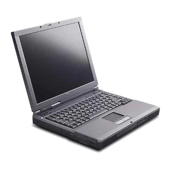
System Overview Getting to Know the Versa Note VX Around the Front of the System Around the Back of the System Around the Left Side of the System Around the Right Side of the System Around the Bottom of the System Internal Components Chipset... - Page 6 Getting to Know the Versa Note VX The Versa Note VX notebook computer offers you a portable system filled with exciting ® resources for home, business or travel. Standard features include a powerful Intel Celeron™, ® Pentium II or Pentium III microprocessor that works together with the latest Peripheral Component Interconnect (PCI) architecture.
-
Page 7: Around The Front Of The System
Around the Front of the System The Versa is compact with features on every side. First, look at the front of the system. The following sections describe front features, beginning with the liquid crystal display (LCD) panel. LCD Panel The Versa Note VX comes with a colour LCD panel that you can adjust for a comfortable viewing position. -
Page 8: Status Led Icons
Control panel A – CD Control Buttons or Password Buttons D – Internet Button B – Status LEDs E – Power Button C – Email Button CD Control Buttons — use to control the CD-ROM drive (stop, reverse, play/pause, and fast forward). -
Page 9: Keyboard Panel And Base Unit
C – Caps Lock Lock Hard Drive Access — lights when the Versa Note VX accesses the hard disk drive, CD-ROM drive or DVD-ROM drive. Diskette Drive Access — lights when the Versa Note VX writes data to or retrieves data from the diskette drive. - Page 10 Keyboard — standard QWERTY-key layout. (Models shipped outside of the U.S. are equipped with country-specific keyboard layouts.) The keyboard is equipped with many features. These include: Function keys Windows keys Cursor control keys Typewriter keys Numeric keypad ...
- Page 11 — Sets standby power management mode on, in Windows 95. Fn-F4 In Windows 95, press any key to resume from Standby mode. No function when Windows 98 configured for Advanced Configuration and Power Interface (ACPI). In Windows 98, Standby is equivalent to Windows 95 Suspend mode.
-
Page 12: Around The Back Of The System
Control keys — Ctrl , and Shift are controls used in conjunction with other keys to change their functions. To use control keys, press and hold the control key while pressing another key. For example, “Press ” means to hold down the key and Ctrl c Ctrl... -
Page 13: Around The Left Side Of The System
USB-equipped peripheral devices (for example, printers, monitors, scanners) to your Versa Note VX. Modem/LAN Port — NEC includes a 56K fax/data modem or mini-PCI LAN. Around the Left Side of the System The left side of your Versa Note VX provides the features shown in the following figure. The left side features are described after the figure. -
Page 14: Right Side Features
Right side features A – Battery Bay C – PC Card Slots B – Fan D – TV Out Battery Bay — Depending upon the model, the battery bay contains a rechargeable Nickel-Metal-Hydride (NiMH) or Lithium-Ion (Li-Ion) battery pack. Fan — Allows your system to cool properly and maintain a safe operating environment. Do not block the fan while the Versa Note VX is in use. -
Page 15: Internal Components
Battery Bay — Equipped with a rechargeable Nickel-Metal-Hydride (NiMH) or (depending on the model) Lithium-Ion (Li-Ion) battery. Battery Release Latch — Slide the latch to the other end and hold it. While holding the latch, slide the battery bay outwards to remove the battery. Memory Module Bay Cover —... - Page 16 YMF752-S Yamaha Audio M38813E4 Mitsubishi Keyboard Controller TIPCI1225 Texas Instruments PCI CardBus Controller 1-12 System Overview...
-
Page 17: System Configuration And Setup
System Configuration and Setup Power Sources for Your Versa Note VX BIOS Setup Updating the BIOS NEC Utilities Application and Driver CD... -
Page 18: Using The Ac Adapter
(For details about its use, refer to the accessory sheet that ships with the option.) Read the following sections for specific information about using the NEC power sources. Using the AC Adapter Use the AC adapter and power cable that came with your Versa Note VX to run your computer on alternating current (AC) power, or to recharge the battery pack. -
Page 19: Connecting The Ac Adapter
Connecting the AC Adapter Note The AC power cable type that your system uses depends on the country where you are using it. Contact the local dealer to purchase the correct power cable. Connect the AC adapter as follows: Connect the AC adapter cable to the power port on the back of your Versa Note VX. Plug one end of the AC power cable into the AC adapter and the other end into a properly grounded 120- or 240-volt wall outlet. -
Page 20: Low Battery Power
To prevent accidental battery ignition or explosion, adhere to the following: n Keep the battery away from extreme heat. n Keep metal objects away from the battery terminals to prevent a short circuit. n Make sure the battery is properly installed in the battery bay. n Read the precautions printed on the battery. -
Page 21: Replacing The Battery
Replacing the Battery The following symptoms indicate that battery life is nearing an end. Replace batteries that display these symptoms. Shorter work times. Discoloration, warping. Hot to the touch. Strange odour. Replace the battery pack installed in your Versa Note VX system as follows. Note Use the batteries in the Versa Note VX computer for which they are designed. -
Page 22: Installing The Battery
Insert the new battery as follows: Locate the alignment groove on the edge of the battery. Locate the alignment groove inside the battery bay. Align the grooves on the battery with the grooves in the bay. Slide the battery into the bay until securely locked into place. Installing the battery Turn over the system. -
Page 23: Precautions For Recharging The Battery
Precautions for Recharging the Battery Adhere to the following precautions when recharging the battery. Use only the NEC battery charger designed for your Versa Note VX battery type. Charge the battery for the specified charge time only. During charging, keep the environmental temperature between 5°C to 35°C (41°F and 95°F). -
Page 24: Cmos Battery
CMOS Battery This battery provides battery backup and prevents data loss in the system’s complementary metal-oxide semiconductor (CMOS) RAM. This memory area contains information on the system’s configuration, for example, date, time, drives, and memory. BIOS Setup Your Versa Note VX computer comes with a hardware program called BIOS Setup that allows you to view and set system parameters. -
Page 25: Looking At Screens
Use the up and down arrow keys (located on the lower right corner of the keyboard) to toggle through the BIOS Setup menu items. Looking at Screens BIOS setup screens have three areas as shown next. Advanced CMOS Setup Parameters — The left side of the screen. This area lists parameters and their current settings. -
Page 26: Checking/Setting System Parameters
Checking/Setting System Parameters The BIOS Setup Utility consists of a number of screens, each representing a specific area of the BIOS. The following tables list the BIOS parameters, their factory default settings, alternate settings, and a description of each setting. See the item-specific help that appears on each Setup screen for more details. -
Page 27: Advanced Cmos Setup
Time — Sets the time, enter the current hour, minute, and second in hr:/min:/sec, 24- hour format. To set the time use the or arrow keys to move from field to field. Use the PgUp key to change the numbers within each field. PgDn Diskette Drive —... -
Page 28: System Security Setup
System Security Setup Use the System Security Setup to establish system passwords. System Security Setup Parameter Default Setting Alternate Setting(s) Change Supervisor Press Enter Password Change User Password Press Enter Boot Password Required Resume Password Required Assign HDD Password Press Enter Internal HDD password Disabled Enabled... -
Page 29: Establishing Hard Disk Drive Passwords
In Windows 98, to establish password protection for resuming from Standby or Hibernation modes you must do the following: Set a Windows password in Control Panel, Password Properties, Change Passwords. Enable the option “Prompt for password when the computer goes off standby,” in Control Panel, Power Management Properties, Advanced. -
Page 30: Moving The Hard Disk Drive
Moving the Hard Disk Drive When a password protected HDD is moved from its original system and installed in another system, error messages appear indicating that the drive is locked. Next, the Security Setup screen appears requiring the user to enter the master password to unlock the drive. Highlight the HDD password line and enter the master password, when prompted. - Page 31 System Switch — Sets the Power button as a power switch or a sleep button. Power Management Under AC — Specifies whether to enable power management features when AC power is in use. When AC power is connected to your Versa Note VX system, power management is usually disabled.
-
Page 32: Boot Device Setup
Quick Boot — Specifies whether or not the system performs all tests during system boot. Silent Boot — Specifies whether or not to display the NEC logo during the system boot. Boot Display Device — Specifies the display device(s) for system boot messages. -
Page 33: Peripheral Setup
Peripheral Setup The Peripheral Setup menu displays the connection locations between the system and the Input/Output (I/O) ports and lets you specify different port assignments as needed. Peripheral Setup Parameter Default Setting Alternate Setting(s) USB Controller Disabled Enabled AC’97 Audio Enabled Disabled Internal Hard Drive... -
Page 34: Updating The Bios
Updating the BIOS The BIOS is code transmitted onto your system’s microprocessor, or central processing unit (CPU). As indicated in this chapter, you use the BIOS Setup utility to configure your system’s software and hardware features. Use the BIOS Update Diskette, for your specific model, only, to update your Versa Note VX system BIOS. -
Page 35: Preparing The Bios Update Diskette
A message similar to the following appears: The NEC BIOS Update Utility should not be used to modify the BIOS in a Versa Note VX system which is docked. If your Versa Note VX is docked, please exit the BIOS Update Utility, power down, and undock your Versa Note VX before running the utility. -
Page 36: Disassembly And Reassembly
Disassembly and Reassembly Required Tools and Equipment Disassembly Reassembly... -
Page 37: Required Tools And Equipment
Required Tools and Equipment All Versa Note VX corrective maintenance procedures can be performed using the following tools: Tweezers Small flat-head screwdriver Small Phillips screwdrivers (# 1 and # 0) needle-nose pliers CPU insertion/extraction tool 3/16” nut driver Right-angled dentist style probe. Disassembly This section contains step-by-step disassembly procedures for the system. -
Page 38: Memory Module And Switch Settings
Remove the battery as follows: Locate the battery release latch. Slide the battery release latch towards the back of the system and hold firmly. Continue to hold the battery release latch as you slide the battery out of the system. Removing the battery A –... -
Page 39: Removing The Memory Module
Locate the memory module slot. To remove a SO-DIMM, press the locking tabs away from the sides of the module until the module pops up. Then, remove the SO-DIMM. Removing the memory module Switch Settings A six-position dip switch is located on the bottom of the system. The switch is accessible by removing the access panel beneath the CD-ROM drive. -
Page 40: Hard Disk Drive
Hard Disk Drive To remove the hard disk drive, follow these steps. Locate the drive access panel on the left side of the system. Open the panel using the notch. Opening the panel A – Drive Access Panel B – Notch Remove the screw that secures the hard disk in the system. -
Page 41: Removing The Disk Drive
Slide the hard disk drive out of the system. Removing the disk drive LED/Button Assembly Follow these steps to remove the LED/Button assembly. Open the LCD panel. Locate the LCD hinge covers. Locate and remove the screw caps and screws on the hinge covers. -
Page 42: Removing The Hinge Covers
Slide each hinge cover toward the outside edge of the system and remove. Removing the hinge covers A – Hinge Cover Lift the LED/button assembly away from the system. Removing the LED/button assembly A – LED/Button Assembly LCD Panel Use the following steps to remove the LCD panel. Remove the LED/button assembly from the system. -
Page 43: Removing The Screws
Locate and remove the two bottom screws securing the LCD panel to the system. Removing the screws A – Screws Turn the system over and open the LCD panel. Locate and remove the two hinge screws. Removing the hinge screws A –... -
Page 44: Keyboard And Heat Plate
Locate and remove the two screws securing the LCD panel connector to the main board. Removing the LCD panel screws A – Screws Pull the LCD panel up and away from the system. Keyboard and Heat Plate Follow these steps to remove the keyboard and heat plate. Remove the LCD panel from the system. -
Page 45: Top Cover
Lay the keyboard key side down over the back of the system. Locate and completely loosen the four screws securing the heat plate to the system. Do not attempt to remove the screws. Loosening the heat plate screws A – Screws B –... - Page 46 Remove the ten screws on the bottom that secure the top cover to the system. Removing the bottom screws A – Screws Turn the system over. Locate and remove the one screw inside the hard disk drive bay that secures the top cover. Removing the drive bay screw A –...
-
Page 47: Removing The Top Cover
Locate and remove the one screw on the top that secures the top cover. Removing the top screw A – Screw Partially lift the top cover. Disconnect the VersaGlide cable from connector P8 on the I/O board. Remove the top cover. Removing the top cover A –... -
Page 48: Removing The Cd-Rom Drive
Turn the top cover over and locate the three screws securing the VersaGlide. Remove the screws. Removing the VersaGlide screws A – VersaGlide B – Screws Slide the VersaGlide assembly away from the top cover tabs and remove the VersaGlide from the top cover. -
Page 49: Audio Board
Audio Board Follow these steps to remove the audio board. Remove the LCD panel, keyboard, heat plate, and top cover from the system. Carefully disconnect the audio board from connector P7 on the main board by lifting the audio board. Disconnecting the audio board A –... - Page 50 DC/DC Board Use the following steps to remove the DC/DC board. Remove the LCD panel, keyboard, heat plate, and top cover from the system. Carefully disconnect and remove the DC/DC board from connectors P9 and P10 on the main board by lifting the DC/DC board. Disconnecting the DC/DC board A –...
- Page 51 I/O Board Follow these steps to remove the I/O board. Remove the LCD panel, keyboard, heat plate, top cover, and audio board from the system. Disconnect the diskette drive cable from connector P6 on the I/O board. Disconnect the CMOS battery from P1 of the I/O board. Carefully disconnect and remove the I/O board from connector P12 on the main board by lifting the I/O board.
-
Page 52: Removing The Cmos Battery
CMOS Battery Use the following steps to remove the CMOS battery. Remove the LCD panel, keyboard, heat plate, top cover, audio board, and I/O board from the system. Remove the CMOS battery from the front of the base assembly. It is secured with two-sided tape. -
Page 53: Diskette Drive
Diskette Drive Use the following steps to remove the diskette drive. Remove the LCD panel, keyboard, heat plate, top cover, audio board, and I/O board from the system. Locate and remove the two screws securing the diskette drive to the base assembly. Removing the diskette drive screws A –... -
Page 54: Removing The Speaker
Speakers Follow these steps to remove the speakers. Remove the LCD panel, keyboard, heat plate, top cover, audio board, and I/O board from the system. Slide the speaker up out of the front of the base assembly. There are two speakers. Removing the speaker A –... -
Page 55: Celeron/Pentium Ii Removal
Main Board Follow these steps to remove the main board. Remove the LCD panel, keyboard, heat plate, top cover, audio board, I/O board, diskette drive, and Kensington lock latch from the system. Locate and remove the four screws that secure the main board to the base assembly. Use the needle-nose pliers to remove the three hex screws. - Page 56 Locate the CPU. Locate and remove two of the CPU stand-offs. Removing the CPU stand-offs A – Stand-offs Locate pin 1 on the CPU (identified by the triangle). Align and place the actuation block of the insertion/extraction tool over pin 1 and the pin diagonally opposite pin 1. Placing the actuation block A –...
-
Page 57: Pentium Iii Removal
Place the push rod into the hole closest to pin 1 of the CPU. To release the CPU, push the rod toward pin 1 until you feel the mechanism unlock. Releasing the CPU Lift the actuation block and the CPU out the system. Only touch the CPU on the sides. -
Page 58: Pc Card Assembly
Only touch the CPU on the sides. Do not touch the top of the die. PC Card Assembly Follow these steps to remove the PC card assembly. Remove the LCD panel, keyboard, heat plate, top cover, audio board, I/O board, diskette drive, Kensington lock latch, and main board from the system. -
Page 59: System Board Layout
System Board Layout Audio Board DC/DC Board I/O Board Main Board... -
Page 60: Audio Board
This following figures show the system boards and connector locations. Audio Board A – Connector P2 (back side) C – Connector P5 B – Connector P1 (back side) DC/DC Board A – Connector P1 B – Connector P2 4-2 System Board Layout... -
Page 61: Main Board
I/O Board A – Connector P5 D – Connector P2 B – Connector P3 (back side) E – Connector P1 C – Connector P6 F – Connector P8 Main Board A – Connector P17 F – Connector P5 B – Connector P15 G –... -
Page 62: Preventive Maintenance
Preventive Maintenance Cleaning the Notebook Exterior Cleaning the Notebook Interior Protecting the Disk Drive Handling the Battery Pack Maintaining the LCD Quality... -
Page 63: Cleaning The Notebook Exterior
Preventive maintenance is limited to cleaning the plastic case, the keyboard, the display screen, and the diskette drive heads, as required. Note Remove the battery and disconnect the AC adapter before performing any maintenance. Voltage is present inside the system unit and LCD even after the system is turned off. -
Page 64: Handling The Battery Pack
Use hard disk maintenance program like DEFRAG under DOS, or acquire Norton Utilities SPEEDISK programs. These programs reorganize your hard disk by eliminating fragmentation and improve the hard disk access time. Handling the Battery Pack The battery pack furnished with the computer requires reasonable care and handling to ensure efficient operation and maximum life. -
Page 65: Troubleshooting
Troubleshooting Quick Troubleshooting Helpful Questions... -
Page 66: Quick Troubleshooting
Quick Troubleshooting This section summarizes problems that may develop during system operation and lists suggested corrective actions. Quick Troubleshooting Problem or Symptoms Corrective Actions No power Check that the AC adapter is plugged into the power port of the notebook. Also, check that the AC adapter is plugged into a properly grounded AC power outlet. - Page 67 Quick Troubleshooting Problem or Symptoms Corrective Actions Diskette drive does not work Check if the diskette drive option is not installed in BIOS Setup. Check if the diskette drive cable is connected properly. Check that the diskette is not faulty. Replace the diskette drive.
- Page 68 Quick Troubleshooting Problem or Symptoms Corrective Actions Serial device does not work Check if the serial port is set to “Auto” in BIOS Setup. Check if the serial device is connected properly. Check if the mouse driver is installed properly. Replace the serial device.
-
Page 69: Helpful Questions
Helpful Questions Here are some helpful questions to ask when troubleshooting the notebook: Is there any external power source connected to the computer? Is the battery fully charged? Is the computer turned on and the Power LED activated? Is the LCD display switched to the external monitor? Are all cables and devices connected properly and securely? Are all needed device drivers installed properly? Is the Suspend Mode activated? Press any key or press the Power/Sleep button to... -
Page 70: Specifications
Specifications System Components Connector Locations Memory Map Interrupt Controllers... -
Page 71: System Components
System Components The following system component specifications are standard except where noted. System Processor Depending on the model: Intel Celeron 400 MHz, 433 MHz, or 466 MHz Intel Pentium II 366 MHz Intel Pentium III 450 MHz or 500 MHz Random Access Memory (RAM) Standard Main Memory —... - Page 72 Main Battery Types: Lithium-Ion (Li-Ion), eight cell – Output Voltage – 14.4v – Capacity – 3,600 mAh Recharging Time Lithium-Ion (Li-Ion): Approximately 3.5 hours when system is not in use; approximately 4 hours when system is in use. Card Slots Two 32-bit card slots for two Type II or one Type III PC card, 5 V or 3.3 V interface LCD Display...
- Page 73 Capacity (depending on the model) 6.0-GB, 12-GB, or larger hard disk drive CD-ROM Drive Thin-type CD-ROM Pack Access Time — 24X Interface — IDE (ATAPI) Photo CD Compatibility — Multisession Photo CD, Single Session Photo CD, Video CD, CS-I, CD-I Ready, CD-G and CD-Plus Mini-PCI Modem K56 Flex compatible V.34 extended rate protocol...
- Page 74 Dimensions System Width — 12 in. (307 mm) Depth — 9.9 in. (252 mm) Height — 1.6 in. (40 mm) (max 44 mm) Weight 6.6 lbs. (3.0 kg) 12.1-inch LCD 6.8 lbs. (3.1 kg) 13.3-inch LCD 7.0 lbs. (3.2 kg) 14.1-inch LCD Recommended Environment Operation Temperature —...
-
Page 75: Connector Locations
Connector Locations The following table shows the system’s connector locations. Connector Locations Connector Location Audio Board Audio Board I/O Board I/O Board I/O Board I/O Board Main Board Main Board Main Board Main Board Main Board Main Board 6 Specifications... -
Page 76: System Memory Map
Memory Map The system supports system and video shadowing, both controlled through complementary metal oxide semiconductor (CMOS). The system supports BIOS as a cacheable area with write protection. The following table shows the system’s memory map. System Memory Map Memory Space Size Function 00000000h-0009FFFFh... -
Page 77: Interrupt Controllers
Interrupt Controllers The following table shows default interrupt level assignments 0 through 15. Interrupts IRQ# Device IRQ00 Internal Timer IRQ01 Keyboard IRQ02 Cascade IRQ03 IRQ04 Serial Port IRQ05 CardBus/Mini-PCI/Sound IRQ06 Diskette Drive IRQ07 Parallel Port IRQ08 Real-time Clock IRQ09 IRQ10 Video IRQ11 Available... - Page 78 Software designed to perform specific functions, like solving business or mathematical problems. AC Adapter A device that connects an NEC Versa portable computer and an AC wall outlet to provide AC power for running the system or recharging the battery. base RAM Area of system memory between 0 and 640 kilobytes available to the user for operating system and application programs.
- Page 79 Electronic timer used to synchronize computer operations. CMOS Complementary Metal Oxide Semiconductor. A chip that contains nonvolatile memory in the NEC Versa. CMOS is backed up by an internal lithium battery that preserves clock/calendar data and system configuration parameters stored in CMOS. cold boot Process of starting up the computer by turning on the power.
- Page 80 (KB) 1024 bytes. Local Area Network. Liquid Crystal Display. An LCD consists of a thin sandwich of two glass plates with sealed edges, containing nematic liquid-crystal material that forms the screen image. The NEC Versa displays are LCD type. load To copy a program into the computer's memory from a storage device.
- Page 81 Usually contained on a single chip that includes an arithmetic logic unit, control logic, and control-memory unit. mode A method of operation; for example, the NEC Versa operates in either normal or power- saving modes. modem MOdulator-DEModulator. A device that links computers over a telephone line.
- Page 82 parameter A characteristic of a device or system. password A string of characters that the user must enter before the system allows access or system privileges. PCMCIA A credit card sized peripheral interface standard for portable devices. Types of PCMCIA cards currently offered by major vendors include fax/modems, LAN, storage cards, and wireless communications devices.
- Page 83 The main printed circuit board inside the system unit into which other boards and major chip components, such as the system microprocessor, are connected. Thin Film Transistor. A type of NEC Versa LCD colour screen that supports 256 colours and provides exceptional screen display.
- Page 84 warm boot Process of resetting the computer without turning off the power through keyboard input (pressing Ctrl, Alt, and Del keys simultaneously) or the reset button. The system returns to an initial or arbitrarily selected condition. write To record or store information to a storage device. Glossary 7...
- Page 85 Index AC adapter Entering BIOS setup, 2-8 specifications, 9-5 Establishing passwords, 2-12 using, 2-2 Application and driver CD Function key combinations, 1-7 installing, 2-22 Function Keys, 1-6 Applications and drivers CD launching, 2-21 Applications and Drivers CD Handling battery pack, 6-3 using, 2-21 Hard disk removing, 3-5...
- Page 86 2-15 NEC customize utility warning tone, 2-15 using, 2-20 switch settings, 3-3 NEC utilities, 2-20 Switch settings, 3-4 NEC Versa disassembly sequence, 3-2 System Numeric keys, 1-8 date, 2-10 switch, 2-15 System dimensions, 9-5 Operating environment, 9-5 System Processor, 9-2...