
Related Manuals for Whirlpool ACM052MM


Summary of Contents for Whirlpool ACM052MM
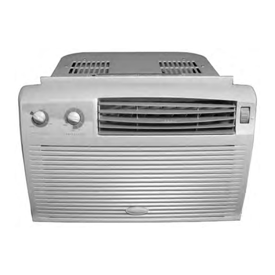
- Page 1 CONSUMER SERVICES TECHNICAL R-96 EDUCATION GROUP PRESENTS Models: ACM052MM, ACM062MM, ACD052MM 2003 5000 & 6000 BTU AIR CONDITIONERS Models: ACQ058MM & ACQ062MM JOB AID Part No. 8178279...
- Page 2 FORWARD This Whirlpool Job Aid, “2003 - 5000 & 6000 BTU Air Conditioners” (Part No. 8178279), provides the technician with information on the installation and service of the 2003 - 5000 & 6000 BTU Air Conditioners. It is to be used as a training Job Aid and Service Manual. For specific information on the model being serviced, refer to the “Use and Care Guide”...
-
Page 3: Table Of Contents
Troubleshooting Chart ....................... 5-2 WIRING DIAGRAMS & STRIP CIRCUITS ................6-1 Wiring Diagram 1—Model ACD052MM ................6-1 Wiring Diagram 2—Models ACM052MM & ACM062MM ..........6-2 Wiring Diagram 3—Models ACQ058MM & ACQ062MM ........... 6-3 Strip Circuits ........................6-4 TECH TIPS ..........................7-1 Installing The Condensate Drain Adapter ................ - Page 4 — NOTES — - iv -...
-
Page 5: General
GENERAL SAFETY FIRST Your safety and the safety of others is very important. We have provided many important safety messages in this Job Aid and on the appliance. Always read and obey all safety messages. This is the safety alert symbol. This symbol alerts you to hazards that can kill or hurt you and others. - Page 6 IMPORTANT Electrostatic Discharge (ESD) Sensitive Electronics ESD problems are present everywhere. ESD may damage or weaken the elec- tronic control assembly. The new control assembly may appear to work well after Electrical Shock Hazard repair is finished, but failure may occur at Connect green ground wire to ground a later date due to ESD stress.
-
Page 7: Whirlpool Model & Serial Number Designations
WHIRLPOOL MODEL & SERIAL NUMBER DESIGNATIONS MODEL NUMBER MODEL NUMBER Q 05 8 M M 0 PRODUCT GROUP A = AIR CONDITIONER PRODUCT IDENTIFICATION C = WARRANTY D = DEHUMIDIFIER O = ROOM A/C CABINETS MODEL TYPE D = VALUE E = HEAT &... -
Page 8: Model & Serial Number Label Locations
MODEL & SERIAL NUMBER LABEL LOCATIONS The Technician Model/Serial Number label location is shown below. Model & Serial Number Location The Consumer Model/Serial Number label location is shown below. Model & Serial Number Location... -
Page 9: Specifications
SPECIFICATIONS Model Number ACD052MM ACQ058MM ACQ062MM ACM052MM & ACM062MM Ratings BTU - Cool 5000 5000 6000 5000 (052)/6000 (062) Energy Efficiency Rating # 10.7 Air Features Air Flow on Turbo (CFM) Air Flow on Medium (CFM) N / A Air Flow on Low (CFM) - Page 10 WHIRLPOOL AIR CONDITIONER WARRANTY Model ACD052MM MANUFACTURER WILL PAY FOR LENGTH OF WARRANTY Replacement parts and repair labor to correct FULL ONE-YEAR defects in materials or workmanship. Service must WARRANTY FROM be provided by an authorized service company. DATE OF PURCHASE WE WILL NOT PAY FOR A.
-
Page 11: Whirlpool Air Conditioner Warranty-Models Acm052Mm
If you need service, first see the “Troubleshooting” section of the Use and Care Guide. After checking “Troubleshooting,” additional help can be found by checking the “Assistance or Service” section, or by calling the Whirlpool Customer Interaction Center, 1-800-253-1301 (toll-free), from anywhere in the U.S.A. - Page 12 — NOTES —...
-
Page 13: Installation Information
INSTALLATION INFORMATION Excessive Weight Hazard Use two or more people to move and install air conditioner. Failure to do so can result in back or other injury. IMPORTANT: Observe all governing codes and ordinances. Check the location where the air conditioner will be installed. - Page 14 Make sure that the back of the air condi- tioner cabinet is tilted down so that water will run to the outside. The tilt should be about 1/2 bubble (B) on a spirit level. If the cabinet is not properly positioned, reposi- tion or shim it to provide the proper tilt.
-
Page 15: Component Access
COMPONENT ACCESS This section instructs you on how to service each component inside the air conditioner. The components and their locations are shown below. COMPONENT LOCATIONS Condenser Overload Protector Compressor Fan Motor Capacitor Power Cord Fan Speed Control Temperature Evaporator Sensor Tube Models ACQ058MM Models ACQ058MM &... -
Page 16: Removing The Side Curtains, Front Grille, Top Cover, & Screen
REMOVING THE SIDE CURTAINS, FRONT GRILLE, TOP COVER, & SCREEN To remove the front grille: a) Remove the four screws (two on each side) from the grille. Electrical Shock Hazard Disconnect power before servicing. Replace all parts and panels before operating. - Page 17 To remove the top cover, remove the To remove the screen: nine screws from the cover, and the two a) Remove the two screws from each side screws from the top curtain guide, and of the screen. remove the cover and the guide. b) Pull the ends of the screen from the slots in the side holders.
-
Page 18: Removing The Fan Speed & Temperature Controls-Models Acd052Mm, Acm052Mm, & Acm062Mm
REMOVING THE FAN SPEED & TEMPERATURE CONTROLS MODELS ACD052MM, ACM052MM, & ACM062MM Depending on which control you are ser- vicing, remove the two screws from the fan speed control or the temperature control. Fan Speed Control Screws Temp Control Screws Electrical Shock Hazard Disconnect power before servicing. -
Page 19: Removing The Electronic Control Assembly & Thermistor-Models Acq058Mm & Acq062Mm
REMOVING THE ELECTRONIC CONTROL ASSEMBLY & THERMISTOR—MODELS ACQ058MM & ACQ062MM Lift the two locking arms, and pull the assembly forward. Locking Arms Electrical Shock Hazard Disconnect power before servicing. Replace all parts and panels before operating. Failure to do so can result in death or electrical shock. -
Page 20: Removing The Power Cord And Capacitor-Models Acm052Mm, Acm062Mm, & Acd052Mm
REMOVING THE POWER CORD AND CAPACITOR MODELS ACM052MM, ACM062MM, & ACD052MM Remove the four screws from the control mounting plate and position it so that you can access the wiring. Electrical Shock Hazard Disconnect power before servicing. Replace all parts and panels before operating. - Page 21 Remove the two screws from the capaci- tor cover, pull the cover forward, and re- move it. Screws Electrical Shock Hazard Connect green ground wires to ground screws. Failure to do so can result in death or electrical shock. Capacitor Cover Perform the following steps to reinstall the capacitor and power cord: To remove the power cord, disconnect...
-
Page 22: Removing The Power Cord And Capacitor-Models Acq058Mm & Acq062Mm
REMOVING THE POWER CORD AND CAPACITOR MODELS ACQ058MM & ACQ062MM Disconnect the smooth power cord lead con- nector from electronic control board termi- nal L1. Smooth Power Cord Lead At Terminal L1 Electrical Shock Hazard Disconnect power before servicing. Replace all parts and panels before operating. - Page 23 To remove the power cord, disconnect the ribbed lead from the capacitor termi- nal. 10. To remove the capacitor: a) Use a 20,000 Ω, 2-watt resistor and discharge the capacitor. Touch the resistor leads to terminals C & H and Electrical Shock Hazard C &...
-
Page 24: Removing The Fan Motor
Remove the side curtains and the front grille (see page 3-2 for the procedures). a) Unclip the thermistor from its holder. b) Remove the lower screw from the two Models ACD052MM, ACM052MM, & green ground wires that are mounted to ACM062MM: the evaporator. - Page 25 Remove the four screws from the brace 10. Loosen the clamp screw on the condenser and remove the brace. fan blade and slide the clamp off the fan. Remove the eight screws from the top air 11. Remove the two screws from the con- guide.
- Page 26 19. Loosen the evaporator fan screw. NOTE: Use the slot in the fan blade to access the Blue screw. 15. Models ACD052MM, ACM052MM, & 20. Pull the evaporator fan off the motor shaft. ACM062MM: Disconnect the black, red, Evaporator Fan Screw and blue wires from the fan speed control terminals.
- Page 27 Carefully lift the fan motor assembly, the condenser fan shroud, and the lower styro- foam air shield, and install them in the unit. Rotate the fan motor so that the wires face down toward the bottom of the unit. Electrical Shock Hazard Connect green ground wires to ground screws.
-
Page 28: Removing The Evaporator
Pull the styrofoam shield out from under the evaporator and remove it (see the Ground photo below). Wire Screws Models ACM052MM, ACM062MM, & ACD052MM: a) Unclip the temperature sensor tube from Models ACQ058MM & ACQ062MM (see the sensor holder. Sensor Holder... - Page 29 Thermistor Holder Lift the top air guide off the upper styrofoam air shields, and rotate the guide to the left, Electronic Control (facing front). Lay the guide on the work Box Assembly Screw surface out of the way. Control Housing 10.
- Page 30 12. Braze on an access valve and discharge Make sure that the rubber wire block is the refrigerant into an approved recovery positioned in its cutout so that there are no system. air leaks around it. 13 . Unbraze the two joints from the evapora- tor and remove the evaporator.
-
Page 31: Removing The Condenser
REMOVING THE CONDENSER Braze on an access valve and discharge the refrigerant into an approved recovery system. Unbraze the top and bottom joints from the condenser and remove the condenser. Electrical Shock Hazard Disconnect power before servicing. Top Condenser Joint Replace all parts and panels before operating. -
Page 32: Removing The Overload Protector & Compressor
REMOVING THE OVERLOAD PROTECTOR & COMPRESSOR Remove the hex cap nut from the terminal cover and remove the cover. Hex Cap Nut Terminal Cover Electrical Shock Hazard Disconnect power before servicing. Replace all parts and panels before operating. Failure to do so can result in death or electrical shock. - Page 33 To remove the compressor: f) Remove the cap nut from each of the feet and lift the compressor off the a) Remove the overload protector (see studs. step 6 on page 3-18 for the procedure). g) Remove the three rubber isolators from b) Disconnect the white wire from com- the compressor.
- Page 34 — NOTES — 3-20...
-
Page 35: Component Testing
COMPONENT TESTING Before testing any of the components, perform • Check all connections before replacing com- the following checks: ponents, looking for broken or loose wires, failed terminals, or wires not pressed into • Control failure can be the result of corrosion connectors far enough. -
Page 36: Fan Speed Control
(C) terminal and the H terminals. LOW COOL L1 to 3 & L1 to 5 The meter should indicate several ohms and gradually return to infinity. ACM052MM & ACM062MM Switch position Contacts closed NONE FAN ONLY L1 to 4 HIGH COOL L1 to 5 &... -
Page 37: Fan Motor
Electrical Shock Hazard Disconnect power before servicing. Replace all parts and panels before operating. Failure to do so can result in death or electrical shock. OVERLOAD PROTECTOR FAN MOTOR Refer to page 3-18 for the procedure for servic- ing the overload protector. Unplug air conditioner or disconnect power. -
Page 38: Compressor
Electrical Shock Hazard Disconnect power before servicing. Replace all parts and panels before operating. Failure to do so can result in death or electrical shock. COMPRESSOR Refer to page 3-18 for the procedure for servic- ing the compressor. Unplug air conditioner or disconnect power. Disconnect the three wires from the com- pressor terminals. -
Page 39: Diagnostics & Troubleshooting
DIAGNOSTICS & TROUBLESHOOTING DIAGNOSTICS—MODELS ACQ058MM & ACQ062MM 3. Press the ADJUST ∧ keypad. The COOL The Diagnostics Mode will test all of the LEDs, the keypads, and the thermistor. To enter the LED will light, and the compressor will op- Diagnostics Mode, perform the following steps. -
Page 40: Troubleshooting Chart
TROUBLESHOOTING CHART PROBLEM PROBABLE CAUSE CORRECTION 1. Unit does not run. 1a. No power to unit. 1a. Check for power at receptacle, good plug contact, fuses of correct size and time delay types. (Have customer contact electrician if no power is avail- able at receptacle.) 1b. - Page 41 PROBLEM PROBABLE CAUSE CORRECTION 6. Compressor stops and 6a. Incorrect voltage. 6a. Check for proper voltage. starts. Too short run- 6b. Temperature control set too warm. 6b.Instruct customer. ning time. 6c. Failed thermistor or thermostat. 6c. Check thermistor by placing it in ice water and check resis- tance (see chart on page 4-1).
- Page 42 PROBLEM PROBABLE CAUSE CORRECTION 9. Evaporator frosting 9a.Low outside air temperature (below 9a.Instruct customer that opera- 65°F). tion at ambient temperatures below 65°F is not considered a normal requirement of the unit. NOTE: 90% frosting of Adjust the controls to a warmer evaporator is normal un- setting.
-
Page 43: Wiring Diagrams & Strip Circuits
WIRING DIAGRAMS & STRIP CIRCUITS WIRING DIAGRAM 1 Model ACD052MM Compressor Overload 2-Speed Motor Ground Capacitor High Comp Thermostat Selector Switch Ground Power Supply... -
Page 44: Wiring Diagram 2—Models Acm052Mm & Acm062Mm
WIRING DIAGRAM 2 Models ACM052MM & ACM062MM Compressor Overload 2-Speed Motor Ground Capacitor High Turbo Comp Thermostat Selector Switch Ground Power Supply... -
Page 45: Wiring Diagram 3—Models Acq058Mm & Acq062Mm
WIRING DIAGRAM 3 Models ACQ058MM & ACQ062MM Compressor Overload 3-Speed Motor Ground Capacitor Thermistor High Turbo Comp. Electronic Control Ground Power Supply... -
Page 46: Strip Circuits
STRIP CIRCUITS Electronic (ACQ) Models Only POWER ON Electronic Control Board COMPRESSOR ON Electronic Control Board Compressor Overload Comp. FAN MOTOR ON 3-Speed Motor Electronic Control Turbo Capacitor High... -
Page 47: Tech Tips
TECH TIPS INSTALLING THE CONDENSATE DRAIN ADAPTER IMPORTANT: Never install the adapter on air WARNING conditioners that are not designed for its use, otherwise damage to the unit may occur. The Condensate Drain Adapter consists of the following parts: 1 Drain Adapter 1 Gasket Electrical Shock Hazard 2 Hex-Head Screws... - Page 48 Perform the following steps to install the Con- Mount the adapter and gasket to the two densate Drain Adapter: predrilled mounting holes in the rear of the base plate with the two hex-head screws Position the gasket and adapter so that provided.
- Page 49 — NOTES —...
- Page 50 — NOTES —...
-
Page 51: Product Specifications
PRODUCT SPECIFICATIONS WARRANTY INFORMATION SOURCES IN THE UNITED STATES: FOR PRODUCT SPECIFICATIONS AND WARRANTY INFORMATION CALL: FOR WHIRLPOOL PRODUCTS: 1-800-253-1301 FOR KITCHENAID PRODUCTS: 1-800-422-1230 FOR ROPER PRODUCTS: 1-800-447-6737 FOR TECHNICAL ASSISTANCE WHILE AT THE CUSTOMER’S HOME CALL: THE TECHNICAL ASSISTANCE LINE: 1-800-253-2870... - Page 52 CORPORATION...