Table of Contents
Advertisement
Quick Links
AIR CONDITIONER
3 phase type
Single / Simultaneous multi system
DESIGN & TECHNICAL MANUAL
SINGLE INDOOR
AU
AU
AU
SIMULTANEOUS MULTI INDOOR
AU
AU
AU
AU
OUTDOOR
AO
AO
AO
G36LRLA
AR
G45LRLA
AR
G54LRLA
G18LVLB
2
AR
×
G22LVLA
2
AR
×
G24LVLA
2
×
G18LVLB
3
×
G36LATT
G45LATT
G54LATT
G36LMLA
AR
G45LMLA
AR
G18LLTB
2
AR
×
G18LLTB
3
AR
×
G45LHTA
AB
G54LHTA
AB
AB
G22LMLA
2
AB
×
G24LMLA
2
AB
×
AB
AB
G36LRTA
G45LRTA
G54LRTA
G18LVTB
2
×
G22LVTA
2
×
G24LVTA
2
×
G18LVTB
3
×
DTR_SSM001E_03
2013.02.22
Advertisement
Chapters
Table of Contents

Related Manuals for Fujitsu AU*G36LRLA


Summary of Contents for Fujitsu AU*G36LRLA
-
Page 1: Air Conditioner
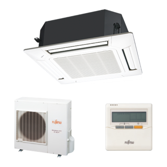
AIR CONDITIONER 3 phase type Single / Simultaneous multi system DESIGN & TECHNICAL MANUAL SINGLE INDOOR G36LRLA G36LMLA G45LHTA G36LRTA G45LRLA G45LMLA G54LHTA G45LRTA G54LRLA G54LRTA SIMULTANEOUS MULTI INDOOR G18LVLB G18LLTB G22LMLA G18LVTB... - Page 2 CONTENTS 1. GENERAL INFORMATION 2. INDOOR UNIT (SINGLE) 3. INDOOR UNIT (SIMULTANEOUS MULTI) 4. OUTDOOR UNIT 5. SYSTEM DESIGN 6. OPTIONAL PARTS...
- Page 3 AIR CONDITIONER 3 phase type Single / Simultaneous multi system 1. GENERAL INFORMATION DTR_SSM001E_03--CHAPTER01 2013.02.22...
-
Page 4: Table Of Contents
CONTENTS 1. GENERAL INFORMATION FEATURES OF SYSTEM ·············································································· 01-01 1-1. PERFORMANCE AND ENERGY SAVING ····················································· 01-01 1-2. EASY INSTALLATION ···················································································01-03 1-3. QUIET OPERATION ·······················································································01-04 1-4. SIMULTANEOUS MULTI SYSTEM ································································01-05 1-5. CONTROL SYSTEM ·······················································································01-06 MODEL LINE UP ····························································································01-09 2-1. INDOOR UNITS ······························································································01-09 2-2. -
Page 5: Features Of System
FEATURES OF SYSTEM 1-1. PERFORMANCE AND ENERGY SAVING „ HIGH PERFORMANCE AND TOP CLASS ENERGY SAVING „ (SINGLE SYSTEM) Both high performance and top class energy saving achieved by adoption of DC inverter. Operating cost suppressed while maintaining comfort. (Cooling) (Heating) AOG36LATT 4.38... - Page 6 PEAK CUT FUNCTION (OPTIONAL PARTS: UTY-XWZXZ2) „ „ Suppresses maximum capacity and performs energy-saving operation and can prevent breaker tripping. This function performs operation by setting a peak current value and reducing the power consumption. * Performance drops by reducing the power consumption preferentially. Level 1 ...
-
Page 7: Easy Installation
1-2. EASY INSTALLATION HIGH INSTALL ABILITY LONG PIPING CORRESPONDENCE „ „ (SINGLE SYSTEM) Long piping provides an outdoor unit and indoor unit layout margin. Max pipe Max height length difference Pre-charge length 4-DIRECTIONS PIPING LOW OUTDOOR „ „ „ „ CONNECTION AIR TEMPERATURE CORRESPONDENCE... -
Page 8: Quiet Operation
1-3. QUIET OPERATION LOW NOISE FUNCTION (OPTIONAL PARTS: UTY-XWZXZ2) „ „ Suppresses operating sound. This function suppresses the outdoor unit noise value to the following 2 level. * Performance may drop depending on the outside air temperature condition, etc. Level 1 ... Rated noise value -2dB Level 2 ... -
Page 9: Simultaneous Multi System
1-4. SIMULTANEOUS MULTI SYSTEM „ IDEAL COMFORTABLE AIR FLOW DISTRIBUTION „ Can support various installation scenes from office to commercial space by same place multi connection of up to 3 units. Indoor units distributed layout according to the shape and number of people and lighting conditions of the room even on wide floors and atypical floors. -
Page 10: Control System
1-5. CONTROL SYSTEM 1-REMOTE CONTROLLER CONTROL „ „ This is the most basic system. Wired type or wireless type remote controller can be selected. Single system „ Refrigerant pipe Refrigerant pipe Indoor unit Indoor unit Transmission/ Power supply cable Remote controller cable Wired R.C. - Page 11 2-REMOTE CONTROLLERS CONTROL „ „ Control locally and from a remote point is possible using 2-remote controllers. Single system „ Refrigerant pipe Refrigerant pipe Indoor unit Indoor unit (Primary) (Secondary) (Primary) Transmission/ Power supply cable Remote controller cable Wired R.C. Wired R.C.
-
Page 12: Group Control
GROUP CONTROL „ „ Max 16 indoor units are simultaneously controlled with a wired remote controller. Refrigerant pipe Refrigerant pipe Indoor unit 1 Indoor unit 2 Indoor unit 0 (Primary) (Secondary) Indoor unit 15 Max 16 indoor units Wireless R.C. * In simultaneous control, the timer and 10°C HEAT function by using the wireless remote controller... -
Page 13: Model Line Up
MODEL LINE UP 2-1. INDOOR UNITS SINGLE SYSTEM „ „ 36 model 45 model 54 model AUG36LRLA AUG45LRLA AUG54LRLA CASSETTE ARG36LMLA ARG45LMLA DUCT ARG45LHTA ARG54LHTA DUCT (High static pressure) ABG36LRTA ABG45LRTA ABG54LRTA CEILING SIMULTANEOUS MULTI SYSTEM „ „ TWIN TRIPLE 18 model x2 22 model x2 24 model x2... -
Page 14: Outdoor Unit
2-2. OUTDOOR UNIT SINGLE SYSTEM INDOOR UNIT 36 model 45 model 54 model SIMULTANEOUS MULTI SYSTEM CONNECTION TYPE Twin Triple INDOOR UNIT 18 model x 2 22 model x 2 24 model x 2 18 model x 3 Outdoor Unit AOG36LATT AOG45LATT AOG54LATT... -
Page 15: Controller
2-3. CONTROLLER Wireless Simple REMOTE Wired Remote Controller Remote IR Receiver Unit Remote CONTROLLER TYPE Controller Controller Note; SET TEMP. START/STOP : Accessory : Optional Parts š ― : It is not possible to connect it. UTY-RVNM UTY-RNNM UTY - LRHA2 UTY - LRHM UTY-RSNM SINGLE SYSTEM š... -
Page 16: Branch Pipes
2-4. BRANCH PIPES Twin connection type Model : UTP - SX236 Liquid pipe Gas pipe Ø9.52 Ø6.35 Ø15.88 Ø12.70 Ø12.70 Ø19.05 Ø6.35 Ø12.70 Twin connection type Model : UTP - SX254 Liquid pipe Gas pipe Adapter Ø15.88 Ø15.88 Ø9.52 Ø9.52 Ø6.35 Ø19.05 Ø12.70... -
Page 17: Cassette Grille
2-5. CASSETTE GRILLE SINGLE SYSTEM „ „ INDOOR UNITS HIGH STATIC TYPE MODEL CASSETTE DUCT PRESSURE CEILING DUCT ― ― ― Cassette grille UTG-UG š Parts „ Cassette grille Model: UTG-UG SIMULTANEOUS MULTI SYSTEM „ „ INDOOR UNITS TYPE MODEL COMPACT... -
Page 18: Others (Optional Parts)
2-6. OTHERS (optional parts) SINGLE SYSTEM „ „ INDOOR UNITS OUTDOOR HIGH STATIC TYPE MODEL UNIT CASSETTE DUCT PRESSURE CEILING DUCT ― ― ― ― š Air outlet shutter plate UTR-YDZC ― ― ― ― Wide panel UTG-AGYA-W š ― ―... - Page 19 SINGLE SYSTEM „ „ Parts „ Air outlet shutter plate Wide panel Model:UTR-YDZC Model:UTG-AGYA-W CASSETTE TYPE CASSETTE TYPE Panel spacer Insulation kit for high humidity Model:UTG-BGYA-W Model:UTZ-KXGA Insulation Kit CASSETTE TYPE CASSETTE TYPE Fresh air intake kit Remote sensor Model:UTZ-VXGA Model:UTY-XSZX HIGH STATIC PRESSURE DUCT TYPE,...
- Page 20 Round flange Drain pump unit Model:UTD-RF204 Model:UTZ - PX1NBA DUCT TYPE, CEILING TYPE DUCT TYPE Drain pump unit External connect kit Model:UTR-DPB24T Model:UTY - XWZX ( x 1 ) ( x 1 ) CASSETTE TYPE, CEILING TYPE CEILING TYPE External connect kit Model:UTY - XWZXZ2 INPUT / OUTPUT OUTDOOR UNIT...
- Page 21 SIMULTANEOUS MULTI SYSTEM „ „ Parts „ Air outlet shutter plate Insulation kit for high humidity Model:UTR-YDZB Model:UTZ-KXGC COMPACT CASSETTE COMPACT CASSETTE TYPE TYPE Fresh air intake kit Square flange Model:UTZ-VXAA Model:UTD-SF045T COMPACT CASSETTE TYPE DUCT TYPE Round flange Long-life filter Model:UTD-RF204 Model:UTD-LF25NA DUCT TYPE...
- Page 22 External connect kit External connect kit Model:UTY - XWZX Model:UTY - XWZXZ2 INPUT / OUTPUT ( x 1 ) COMPACT CASSETTE TYPE, ( x 1 ) FLOOR / CEILING TYPE OUTDOOR UNIT - (01-18) -...
-
Page 23: Indoor Unit (Single
AIR CONDITIONER 3 phase type Single / Simultaneous multi system 2. INDOOR UNIT (SINGLE) DTR_SSM001E_03--CHAPTER02 2013.02.22... - Page 24 CONTENTS 2. INDOOR UNIT (SINGLE) FEATURES ·······································································································02-01 1-1. CASSETTE TYPE ······························································································02-01 1-2. DUCT TYPE ·······································································································02-04 1-3. HIGH STATIC PRESSURE DUCT TYPE ···························································02-06 1-4. CEILING TYPE ··································································································02-08 REMOTE CONTROLLER ············································································· 02-10 2-1. WIRED REMOTE CONTROLLER ····································································· 02-10 2-2. WIRELESS REMOTE CONTROLLER ······························································...
- Page 25 CONTENTS 2. INDOOR UNIT (SINGLE) 7-2. DUCT TYPE ·······································································································02-59 7-2-1. NORMAL MODE ························································································02-59 7-2-2. HIGH STATIC PRESSURE MODE 1 ······························································02-61 7-2-3. HIGH STATIC PRESSURE MODE 2 ······························································02-63 7-2-4. HIGH STATIC PRESSURE MODE 3 ······························································02-65 7-3. HIGH STATIC PRESSURE DUCT TYPE ···························································02-67 7-4.
-
Page 26: Features
FEATURES 1-1. CASSETTE TYPE MODEL „ „ AUG36LRLA / AOG36LATT AUG45LRLA / AOG45LATT AUG54LRLA / AOG54LATT FEATURES „ „ Energy efficiency class „ MODEL AUG36LRLA Cooling Heating Advancement in comfort „ • Quiet operation was realized by adoption of new type turbo fan •... -
Page 27: Economy Operation
Wide & powerful airflow The wind is widely delivered by a high efficiency fan and round flap. [ m ] Side view [ m ] Airflow range of 2m / s Improvement of installation & maintenance „ • Adjustment of nut is possible after installation Mounting position of body can be fine adjusted after Decoration panel mounting. -
Page 28: Auto Restart
FUNCTION SETTING „ „ Outlet direction selection „ • Performs operation matched to the number of outlets when 4 directions are unnecessary and outlets are blocked when the ceiling cassette is installed in a corner, etc. 4-way direction 3-way direction 4-way direction mode: Set when there are 4 outlets (shipped state). -
Page 29: Duct Type
1-2. DUCT TYPE MODEL „ „ ARG36LMLA / AOG36LATT ARG45LMLA / AOG45LATT FEATURES „ „ Energy efficiency class „ MODEL ARG36LMLA Cooling Heating Flexible installation „ A high installation of degree of freedom according to the construction of the ceiling. Embedded in Ceiling Hanging from Ceiling Slim &... - Page 30 Two-direction drain piping „ Duct indoor unit Two-direction drain piping Easy maintenance „ It can easily access the fan and the motor by the divided panel structure. 1. Control box Structural improvement is attained by making the bottom panel two pieces, front and rear. 2.
-
Page 31: High Static Pressure Duct Type
1-3. HIGH STATIC PRESSURE DUCT TYPE MODEL „ „ ARG45LHTA / AOG45LATT ARG54LHTA / AOG54LATT FEATURES „ „ Improvement of market suitability „ Considerable improvement of installation work by compact size and light weight considering with the conditions of installation in the ceiling. The size which the indoor unit can be installed in the spacing between the beams is required for the installation in the ceiling. - Page 32 Operation sound (Low noise) „ Turbulent air flow is reduced by cutting off the corners of conventional indoor unit front panel and fan case Low noise is realized by adopting plastic case, plastic fan Heat exchanger Turbulent air flow Plastic fan Ø225 mm Heat exchanger Casing (Plastic)
-
Page 33: Ceiling Type
1-4. CEILING TYPE MODEL „ „ ABG36LRTA / AOG36LATT ABG45LRTA / AOG45LATT ABG54LRTA / AOG54LATT FEATURES „ „ Energy efficiency class „ MODEL ABG36LRTA Cooling Heating Quiet operation „ Air flow mode can be set in 4 steps and more detailed air flow setting is possible. Economy operation „... - Page 34 Double auto swing „ Combination of up/down and right/left air direction swing allows three-dimensional air direction control. Since up/down air direction flaps operate automatically, according to the operating mode of the unit, it is possible to set the air direction based on the operating mode. Right and Left Swing Up and Down Swing 5 steps selectable...
-
Page 35: Remote Controller
REMOTE CONTROLLER 2-1. WIRED REMOTE CONTROLLER FEATURES „ „ ● Various timer setup (ON/OFF/WEEKLY) are possible. ● Equipped with weekly timer as standard function. (Start/Stop function is twice per day for a week) ● When setting up a timer, start/stop and a temperature setup can be changed. - Page 36 FUNCTIONS „ „ START/STOP button Pressed to start and stop operation. SET TEMP. button Selects the setting temperature. MODE button Selects the operating mode(AUTO, HEAT, FAN, COOL, DRY). FAN button Selects the fan speed (AUTO, QUIET, LOW, MED, HIGH). ECONOMY (THERMO SENSOR) button Turns the economy efficient mode on and off.
-
Page 37: System Diagram
SYSTEM DIAGRAM „ „ 1-remote controller 2-remote controllers „ „ Indoor unit Indoor unit A , B , C : Remote controller cable. Refer to next page Primary Primary Secondary Secondary for detail specifications. < < 500m ; B+C 500m Remote controller Remote controller ELECTRICAL WIRING... -
Page 38: Wiring Specifications
INSTALLATION „ „ Connect the end of remote controller cable directly to the exclusive terminal block. M4 screw Outdoor unit / Remote controller Remote Power supply terminal block controller terminal block Indoor unit cable Terminal block Note : It may be failed if it is connected to the outdoor unit or the terminal block for power supply. PACKING LIST (ACCESSORIES) „... -
Page 39: Wireless Remote Controller
2-2. WIRELESS REMOTE CONTROLLER FEATURES „ „ Four kinds of timer setup (ON/OFF/PROGRAM/SLEEP) are possible. „ Can be used jointly with wired remote controllers. „ Easy to change custom code (4 patterns). „ Built-in timers „ Select from four different timer programs (ON/OFF/PROGRAM/SLEEP). Program timer „... - Page 40 FUNCTIONS „ „ MODE button Selects the operating mode (AUTO, COOL, DRY, FAN, HEAT). /Start / end R.C. signal code change. (Max 4 types) 10°C HEAT button * In Group control system, does not function. SET TEMP. button ( ▲ / ▼ ) Sets the indoor temp./ Sets R.C.
- Page 41 SYSTEM DIAGRAM „ „ Signal receiver ● Control signal might not be recognized in following cases: window (i) A curtain or a wall, etc. exists between transmitter and receiver. (ii) There is an instant-start type (inverter type, etc.) fluorescent lamp Signal transmitter in the room.
- Page 42 PACKING LIST (ACCESSORIES) „ „ Name and shape Quantity Application Remote controller holder Use as remote controller holder Tapping screw ( M3 x 12 mm ) For remote controller holder installation Battery For remote controller [ 1.5V (R03 / AAA) ] SPECIFICATIONS „...
-
Page 43: Cassette Type
SPECIFICATIONS 3-1. CASSETTE TYPE CASSETTE MODEL Type INVERTER HEATPUMP Model name AUÛG36LRLA AUÛG45LRLA AUÛG54LRLA Power source 3N ~ 400V 50Hz Available voltage range 3N ~ 342V - 457V 50Hz 10.0 12.5 14.0 Rated Btu/h 34100 42700 47800 Cooling 4.7 - 11.4 5.0 - 14.0 5.4 - 16.0 Min.-Max. - Page 44 Model name AUG36LRLA Cooling Energy efficiency class Heating (Average) Cooling 10.0 (35°C) Pdesign Heating (Average) 10.0 (-10°C) SEER Cooling 6.50 kWh/kWh SCOP Heating (Average) 4.30 Annual energy consumption kWh/a QHE (Average) 3253 Cooling Sound power level High dB (A) Heating - (02-19) -...
-
Page 45: Duct Type
3-2. DUCT TYPE DUCTED MODEL Type INVERTER HEATPUMP Model name ARÛG36LMLA ARÛG45LMLA Power source 3N~ 400V 50Hz Available voltage range 3N~ 342V - 457V 50Hz 10.0 12.5 Rated Btu/h 34100 42700 Cooling 4.7 - 11.4 5.0 - 14.0 Min.-Max. Btu/h 16000 - 38900 17100 - 47800 Capacity... - Page 46 Model name ARG36LMLA Cooling Energy efficiency class Heating (Average) Cooling 10.0 (35°C) Pdesign Heating (Average) 10.0 (-10°C) SEER Cooling 5.80 kWh/kWh SCOP Heating (Average) 4.00 Annual energy consumption kWh/a QHE (Average) 3497 Cooling Sound power level High dB (A) Heating - (02-21) -...
-
Page 47: High Static Pressure Duct Type
3-3. HIGH STATIC PRESSURE DUCT TYPE DUCTED MODEL Type INVERTER HEATPUMP Model name ARÛG45LHTA ARÛG54LHTA Power source 3N~ 400V 50Hz Available voltage range 3N~ 342V - 457V 50Hz 12.5 14.0 Rated 42700 47800 Btu/h Cooling 5.0 - 14.0 5.4 - 16.0 Min.-Max. -
Page 48: Ceiling Type
3-4. CEILING TYPE CEILING MODEL Type INVERTER HEATPUMP Model name ABG36LRTA ABG45LRTA ABG54LRTA Power source 3N~ 400V 50Hz Available voltage range 3N~ 342V - 457V 50Hz 10.0 12.5 14.0 Rated 34100 42700 47800 Btu/h Cooling 4.7-11.4 5.0-14.0 5.4-16.0 Min.-Max. Btu/h 16000-38900 17000-47800 18400-54600... - Page 49 Model name ABG36LRTA Cooling Energy efficiency class Heating (Average) Cooling 10.0 (35°C) Pdesign Heating (Average) 10.0 (-10°C) SEER Cooling 6.10 kWh/kWh SCOP Heating (Average) 4.10 Annual energy consumption kWh/a QHE (Average) 3414 Cooling Sound power level High dB (A) Heating - (02-24) -...
-
Page 50: Dimensions
DIMENSIONS 4-1. CASSETTE TYPE MODEL : AUG36LR, AUG45LR, AUG54LR „ „ Ceiling opening and hanging bolt pitch „ (Unit : mm) 950 (Panel frame) 860 - 910 (Ceiling opening) 20 - 45 20 - 45 840 (Body frame) 795 (Hanging bolt pitch) Refrigerant piping and drain piping positions „... - Page 51 INSTALLATION PLACE „ „ (Unit : mm) Strong and durable ceiling 298 or more 1,500 3,000 or more or more Obstruction 1,800 or more Floor H (The maximum height from floor to ceiling) (mm) Model name AUG36LR AUG45LR AUG54LR Low mode 2,700 2,700 2,700...
-
Page 52: Duct Type
4-2. DUCT TYPE MODEL : ARG36LM, ARG45LM „ „ (Unit : mm) Front view Side view (L) Side view (R) Top view Rear view „ Refrigerant piping flare connection (Gas) „ Refrigerant piping flare connection (Liquid) „ Drain piping connection „... - Page 53 INSTALLATION PLACE „ „ (Unit : mm) 2500 or more (When no ceiling) 300 or more 150 or more Floor MAINTENANCE SPACE „ „ It shall be possible to install and remove It shall be possible to install and remove the control box.
-
Page 54: High Static Pressure Duct Type
4-3. HIGH STATIC PRESSURE DUCT TYPE MODEL : ARG45LH, ARG54LH „ „ (Unit : mm) Rear view Side view (R) Side view (L) Top view Front view „ Refrigerant piping flare connection (Liquid) „ Refrigerant piping flare connection (Gas) - (02-29) -... - Page 55 INSTALLATION PLACE „ „ (Unit : mm) Installation by which service space is made on top of the unit (recommended). 350 or more 450 or more (Service space) Service access Installation by which service is carried out from the bottom of the unit. 20 or more 450 or more...
-
Page 56: Ceiling Type
4-4. CEILING TYPE MODEL : ABG36LR, ABG45LR, ABG54LR „ „ (Unit : mm) Top view Side view Rear view Suspension bolt pitch 1,600 Dimensions (Space Required for Installation) INDOOR UNIT (Top view) Suspension bolt should extend INDOOR UNIT outward 30 to 75. „... - Page 57 INSTALLATION PLACE „ „ (Unit : mm) Ceiling INDOOR UNIT 80 or more 150 or more Ceiling 10 or more Obstruction Floor Ceiling panel INDOOR UNIT Ceiling panel 80 or more 150 or more 10 or more Obstruction Floor - (02-32) -...
-
Page 58: Wiring Diagrams
WIRING DIAGRAMS 5-1. CASSETTE TYPE MODEL : AUG36LR, AUG45LR, AUG54LR „ „ - (02-33) -... -
Page 59: Duct Type
5-2. DUCT TYPE MODEL : ARG36LM, ARG45LM „ „ - (02-34) -... -
Page 60: High Static Pressure Duct Type
5-3. HIGH STATIC PRESSURE DUCT TYPE MODEL : ARG45LH, ARG54LH „ „ - (02-35) -... -
Page 61: Ceiling Type
5-4. CEILING TYPE MODEL : ABG36LR, ABG45LR, ABG54LR „ „ - (02-36) -... -
Page 62: Cooling Capacity
CAPACITY TABLE 6-1. COOLING CAPACITY 6-1-1. CASSETTE TYPE This table is created using the maximum capacity. MODEL : AUG36LR „ „ 30.0 Indoor temperature °CDB °CWB °CDB 8.83 6.90 1.40 9.84 6.95 1.42 10.17 7.55 1.43 10.85 7.58 1.44 11.18 8.18 1.45 11.85... -
Page 63: Duct Type
6-1-2. DUCT TYPE This table is created using the maximum capacity. MODEL : ARG36LM „ „ 30.8 Indoor temperature °CDB °CWB °CDB 8.60 6.85 1.44 9.58 6.89 1.46 9.91 7.49 1.47 10.56 7.51 1.48 10.89 8.11 1.49 11.54 8.08 1.51 12.19 8.61 1.52... -
Page 64: High Static Pressure Duct Type
6-1-3. HIGH STATIC PRESSURE DUCT TYPE This table is created using the maximum capacity. MODEL : ARG45LH „ „ 55.8 Indoor temperature °CDB °CWB °CDB 10.61 9.69 1.69 11.82 9.75 1.72 12.22 10.60 1.73 13.02 10.64 1.75 13.43 11.49 1.76 14.23 11.44 1.77... -
Page 65: Ceiling Type
6-1-4. CEILING TYPE This table is created using the maximum capacity. MODEL : ABG36LR „ „ 31.7 Indoor temperature °CDB °CWB °CDB 8.61 6.98 1.41 9.59 7.02 1.43 9.92 7.63 1.44 10.57 7.65 1.45 10.90 8.27 1.46 11.55 8.23 1.47 12.21 8.77 1.49 8.58 6.78... -
Page 66: Heating Capacity
6-2. HEATING CAPACITY 6-2-1. CASSETTE TYPE This table is created using the maximum capacity. MODEL : AUG36LR „ „ 30.0 Indoor temperature °CDB °CDB °CWB 10.74 4.26 10.48 4.35 10.23 4.44 9.97 4.53 9.71 4.61 11.90 4.26 11.62 4.35 11.34 4.44 11.05 4.52... -
Page 67: Duct Type
6-2-2. DUCT TYPE This table is created using the maximum capacity. MODEL : ARG36LM „ „ 30.8 Indoor temperature °CDB °CDB °CWB 10.72 4.41 10.47 4.50 10.21 4.59 9.95 4.68 9.70 4.78 11.89 4.41 11.60 4.50 11.32 4.59 11.04 4.68 10.75 4.78 13.00... -
Page 68: High Static Pressure Duct Type
6-2-3. HIGH STATIC PRESSURE DUCT TYPE This table is created using the maximum capacity. MODEL : ARG45LH „ „ 55.8 Indoor temperature °CDB °CDB °CWB 12.39 5.20 12.09 5.31 11.80 5.42 11.50 5.52 11.21 5.63 13.58 5.20 13.26 5.31 12.93 5.42 12.61 5.53... -
Page 69: Ceiling Type
6-2-4. CEILING TYPE This table is created using the maximum capacity. MODEL : ABG36LR „ „ 31.7 Indoor temperature °CDB °CDB °CWB 10.71 4.43 10.45 4.52 10.20 4.62 9.94 4.71 9.69 4.80 11.87 4.43 11.59 4.52 11.31 4.61 11.02 4.71 10.74 4.80 12.99... -
Page 70: Fan Performance (And Capacity*)
FAN PERFORMANCE (AND CAPACITY*) 7-1. CASSETTE TYPE Note: Condition 7-1-1. AIR VELOCITY DISTRIBUTION Fan speed : High Operation mode : FAN MODEL : AUG36LR (STANDARD MODE) Ceiling mode : Standard „ „ 4-way air outlet „ Unit : m/s TOP VIEW VERTICAL FLAP : Upward Unit : m/s... - Page 71 Note: Condition Fan speed : High Operation mode : FAN Ceiling mode : Standard 3-way air outlet „ Unit : m/s TOP VIEW VERTICAL FLAP : Upward Unit : m/s SIDE VIEW VERTICAL FLAP : Upward Unit : m/s SIDE VIEW VERTICAL FLAP : Downward - (02-46) -...
- Page 72 Note: Condition Fan speed : High Operation mode : FAN MODEL : AUG45LR (STANDARD MODE) Ceiling mode : Standard „ „ 4-way air outlet „ Unit : m/s TOP VIEW VERTICAL FLAP : Upward Unit : m/s SIDE VIEW VERTICAL FLAP : Upward Unit : m/s SIDE VIEW...
- Page 73 Note: Condition Fan speed : High Operation mode : FAN Ceiling mode : Standard 3-way air outlet „ Unit : m/s TOP VIEW VERTICAL FLAP : Upward Unit : m/s SIDE VIEW VERTICAL FLAP : Upward Unit : m/s SIDE VIEW VERTICAL FLAP : Downward - (02-48) -...
- Page 74 Note: Condition Fan speed : High Operation mode : FAN MODEL : AUG54LR (STANDARD MODE) Ceiling mode : Standard „ „ 4-way air outlet „ Unit : m/s TOP VIEW VERTICAL FLAP : Upward Unit : m/s SIDE VIEW VERTICAL FLAP : Upward Unit : m/s SIDE VIEW...
- Page 75 Note: Condition Fan speed : High Operation mode : FAN Ceiling mode : Standard 3-way air outlet „ Unit : m/s TOP VIEW VERTICAL FLAP : Upward Unit : m/s SIDE VIEW VERTICAL FLAP : Upward Unit : m/s SIDE VIEW VERTICAL FLAP : Downward - (02-50) -...
- Page 76 Note: Condition Fan speed : High Operation mode : FAN MODEL : AUG36LR (SPECIAL UPWARD MODE) Ceiling mode : Standard „ „ 4-way air outlet „ Unit : m/s SIDE VIEW VERTICAL FLAP : Special upward MODEL : AUG45LR (SPECIAL UPWARD MODE) „...
-
Page 77: Air Flow
7-1-2. AIR FLOW MODEL : AUG36LR (4-WAY OUTLET) „ „ Cooling / Heating „ Number of Fan speed rotations Air flow (r.p.m.) 1800 HIGH 1059 1430 1250 1150 QUIET MODEL : AUG45LR (4-WAY OUTLET) „ „ Cooling / Heating „ Number of Fan speed rotations... - Page 78 MODEL : AUG54LR (4-WAY OUTLET) „ „ Cooling / Heating „ Number of Fan speed rotations Air flow (r.p.m.) 2000 HIGH 1177 1700 1000 1530 1300 QUIET - (02-53) -...
- Page 79 MODEL : AUG36LR (3-WAY OUTLET) „ „ Cooling / Heating „ Number of Fan speed rotations Air flow (r.p.m.) 1640 HIGH 1340 1160 1060 QUIET MODEL : AUG45LR (3-WAY OUTLET) „ „ Cooling / Heating „ Number of Fan speed rotations Air flow (r.p.m.)
- Page 80 MODEL : AUG54LR (3-WAY OUTLET) „ „ Cooling / Heating „ Number of Fan speed rotations Air flow (r.p.m.) 1740 HIGH 1024 1520 1360 1140 QUIET *Air flow can be changed according to the direction in which the outlet is blocked. - (02-55) -...
-
Page 81: Fresh Air
7-1-3. FRESH AIR MODEL : AUG36LR, AUG45LR, AUG54LR „ „ Air flow volume - Static pressure of Fresh air intake characteristic „ Duct (Inside Dia. ø70mm) Duct Fan Static pressure required to take in fresh air Air flow (m Installation „... -
Page 82: Duct Connection
7-1-4. DUCT CONNECTION MODEL: AU G36LR, AUG45LR, AUG54LR „ „ Outlet air „ AU G36LR Duct (Inside size. 350mm×100mm) Fan Speed High 1-way Fan Speed High 2-way Fan Speed Quiet 1-way L=10m Fan Speed L=5m Quiet 2-way L=1m Air flow (m AUG45LR Fan Speed High 1-way... - Page 83 PRECAUTIONS WHILE CONNECTING AIR OUTLET DUCT „ „ • Connect the air outlet duct at up to two locations among the four duct connection locations. (Do not connect ducts at three or more locations.) • Blow-off pattern when a branch duct is installed bi-directional branching, main unit bi-directional branching Branch Close...
-
Page 84: Duct Type
7-2. DUCT TYPE 7-2-1. NORMAL MODE MODEL : ARG36LM „ „ Static pressure (Pa) 2020 1990 1850 (Heating) 1189 1171 1089 1970 1940 1800 (Cooling) 1160 1142 1060 1685 1595 1550 1325 1255 1230 1020 1000 Quiet Q-h Characteristic curve (Cooling) (Heating) Quiet... - Page 85 MODEL : ARG45LM „ „ Static pressure (Pa) 2250 2223 2010 1324 1308 1183 1710 1685 1585 1540 1006 1325 1250 1220 1020 Quiet Q-h Characteristic curve Quiet 1,100 1,300 1,500 1,700 1,900 2,100 2,300 (m Air flow COOLING Capacity 1,100 1,300 1,500...
-
Page 86: High Static Pressure Mode 1
7-2-2. HIGH STATIC PRESSURE MODE 1 MODEL : ARG36LM „ „ Static pressure (Pa) 1950 1860 1700 1148 1095 1001 1730 1620 1520 1018 1340 1265 1190 1080 Quiet Q-h Characteristic curve Quiet 1,100 1,300 1,500 1,700 1,900 2,100 2,300 (m Air flow COOLING Capacity... - Page 87 MODEL : ARG45LM „ „ Static pressure (Pa) 2100 2075 1970 1810 1236 1221 1159 1065 1750 1555 1520 1030 1350 1190 1070 Quiet Q-h Characteristic curve Quiet 1,100 1,300 1,500 1,700 1,900 2,100 2,300 (m Air flow COOLING Capacity 1,100 1,300 1,500...
-
Page 88: High Static Pressure Mode 2
7-2-3. HIGH STATIC PRESSURE MODE 2 MODEL : ARG36LM „ „ Static pressure (Pa) 1850 1600 1089 1600 1400 1340 1180 1090 Quiet Q-h Characteristic curve Quiet 1,100 1,300 1,500 1,700 1,900 2,100 2,300 (m Air flow COOLING Capacity 1,100 1,300 1,500 1,700... - Page 89 MODEL : ARG45LM „ „ Static pressure (Pa) 1900 1660 1118 1600 1400 1340 1180 1090 Quiet Q-h Characteristic curve Quiet 1,100 1,300 1,500 1,700 1,900 2,100 2,300 (m Air flow COOLING Capacity 1,100 1,300 1,500 1,700 1,900 2,100 2,300 (m Air flow HEATING Capacity...
-
Page 90: High Static Pressure Mode 3
7-2-4. HIGH STATIC PRESSURE MODE 3 MODEL : ARG36LM „ „ Static pressure (Pa) 1730 1500 1018 1530 1310 1330 1140 1110 Quiet Q-h Characteristic curve Quiet 1,100 1,300 1,500 1,700 1,900 2,100 2,300 (m Air flow COOLING Capacity 1,100 1,300 1,500 1,700... - Page 91 MODEL : ARG45LM „ „ Static pressure (Pa) 1730 1500 1018 1530 1310 1330 1140 1110 Quiet Q-h Characteristic curve Quiet 1,100 1,300 1,500 1,700 1,900 2,100 2,300 (m Air flow COOLING Capacity 1,100 1,300 1,500 1,700 1,900 2,100 2,300 (m Air flow HEATING Capacity...
-
Page 92: High Static Pressure Duct Type
7-3. HIGH STATIC PRESSURE DUCT TYPE MODEL : ARG45LH „ „ Static pressure (Pa) 3350 3150 2950 2700 2450 2280 1900 1972 1854 1736 1589 1442 1342 1118 2850 2700 2520 2350 2160 1970 1750 1677 1589 1483 1383 1271 1159 1030 2430... - Page 93 MODEL : ARG54LH „ „ Static pressure (Pa) 3350 3150 2950 2700 2450 2280 1900 1972 1854 1736 1589 1442 1342 1118 2850 2700 2520 2350 2160 1970 1750 1677 1589 1483 1383 1271 1159 1030 2430 2310 2180 2050 1900 1750 1430...
-
Page 94: Ceiling Type
7-4. CEILING TYPE Note: Condition 7-4-1. AIR VELOCITY DISTRIBUTION Fan speed : High Operation mode : FAN MODEL : ABG36LR „ „ Unit : m/s 0.25 Unit : m/s 10 11 12 13 14 15 16 17 18 TOP VIEW VERTICAL FLAP : UPWARD HORIZONTAL FLAP : CENTER 0.25... - Page 95 Note: Condition Fan speed : High Operation mode : FAN MODEL : ABG45LR „ „ Unit : m/s 0.25 Unit : m/s 10 11 12 13 14 15 16 17 18 TOP VIEW VERTICAL FLAP : UPWARD HORIZONTAL FLAP : CENTER 0.25 Unit : m/s 10 11 12 13 14...
- Page 96 Note: Condition Fan speed : High Operation mode : FAN MODEL : ABG54LR „ „ Unit : m/s 0.25 Unit : m/s 2 3 4 6 7 8 9 10 11 12 13 14 15 16 17 TOP VIEW VERTICAL FLAP : UPWARD HORIZONTAL FLAP : CENTER 0.5 0.25 Unit : m/s...
-
Page 97: Air Flow
7-4-2. AIR FLOW MODEL : ABG36LR „ „ Cooling „ Number of Fan speed rotations Air flow (r.p.m.) 1900 HIGH 1100 1738 1500 1200 1000 QUIET zHeating „ Number of Fan speed rotations Air flow (r.p.m.) 1900 HIGH 1100 1738 1500 1200 1000... - Page 98 MODEL : ABG45LR „ „ Cooling „ Number of Fan speed rotations Air flow (r.p.m.) 2100 HIGH 1200 1236 1700 1000 1000 1400 1100 QUIET zHeating „ Number of Fan speed rotations Air flow (r.p.m.) 2100 HIGH 1200 1236 1700 1000 1000 1400...
- Page 99 MODEL : ABG54LR „ „ Cooling „ Number of Fan speed rotations Air flow (r.p.m.) 2300 HIGH 1360 1354 1950 1150 1148 1600 1300 QUIET zHeating „ Number of Fan speed rotations Air flow (r.p.m.) 2300 HIGH 1340 1354 1950 1150 1148 1600...
-
Page 100: Fresh Air Characteristic
7-4-3. FRESH AIR CHARACTERISTIC MODEL : ABG36LR, ABG45LR, ABG54LR „ „ Air flow volume - Static pressure of Fresh air intake characteristic „ (mmAq) (Pa) 98 Fresh air flow (m Installation „ For half concealed installation Fresh air inlet position UTD-RF204 (Optional parts) Flexible duct * 1 *1: Locally procured parts... -
Page 101: Operation Noise
OPERATION NOISE 8-1. NOISE LEVEL CURVE Condition Ceiling mode : Standard 8-1-1. CASSETTE TYPE Air outlet : 4-way air outlet MODEL : AUG36LR „ „ Cooling Heating „ „ NC-65 NC-65 NC-60 NC-60 NC-55 NC-55 NC-50 NC-50 NC-45 NC-45 HIGH HIGH NC-40 NC-40... - Page 102 Condition Ceiling mode : Standard MODEL : AUG54LR „ „ Air outlet : 4-way air outlet Cooling Heating „ „ NC-65 NC-65 NC-60 NC-60 NC-55 NC-55 NC-50 NC-50 HIGH HIGH NC-45 NC-45 NC-40 NC-40 NC-35 NC-35 NC-30 NC-30 NC-25 NC-25 QUIET QUIET NC-20...
-
Page 103: 8-1-2. Duct Type
8-1-2. DUCT TYPE Condition Static pressure : 47Pa MODEL : ARG36LM „ „ Static pressure mode : Normal Cooling Heating „ „ NC-65 NC-65 NC-60 NC-60 NC-55 NC-55 NC-50 NC-50 NC-45 NC-45 HIGH HIGH NC-40 NC-40 NC-35 NC-35 NC-30 NC-30 NC-25 NC-25 QUIET... -
Page 104: 8-1-3. High Static Pressure Duct Type
8-1-3. HIGH STATIC PRESSURE DUCT TYPE Condition Static pressure : 100Pa MODEL : ARG45LH „ „ Cooling Heating „ „ NC-65 NC-65 NC-60 NC-60 NC-55 NC-55 NC-50 NC-50 HIGH HIGH NC-45 NC-45 NC-40 NC-40 NC-35 NC-35 NC-30 NC-30 NC-25 NC-25 NC-20 NC-20 NC-15... -
Page 105: Ceiling Type
8-1-4. CEILING TYPE MODEL : ABG36LR „ „ Cooling Heating „ „ NC-65 NC-65 NC-60 NC-60 NC-55 NC-55 NC-50 NC-50 HIGH HIGH NC-45 NC-45 NC-40 NC-40 NC-35 NC-35 NC-30 NC-30 QUIET NC-25 NC-25 QUIET NC-20 NC-20 NC-15 NC-15 1,000 2,000 4,000 8,000 1,000... - Page 106 MODEL : ABG54LR „ „ Cooling Heating „ „ NC-65 NC-65 NC-60 NC-60 NC-55 NC-55 HIGH HIGH NC-50 NC-50 NC-45 NC-45 NC-40 NC-40 NC-35 NC-35 NC-30 NC-30 QUIET QUIET NC-25 NC-25 NC-20 NC-20 NC-15 NC-15 1,000 2,000 4,000 8,000 1,000 2,000 4,000 8,000...
-
Page 107: Sound Level Check Point
8-2. SOUND LEVEL CHECK POINT „ CASSETTE TYPE „ Microphone 1.5 m Microphone - (02-82) -... - Page 108 „ DUCT TYPE „ Measuring duct Measuring duct Set the static pressure as rating in this area Microphone Microphone „ HIGH STATIC PRESSURE DUCT TYPE „ Measuring duct Measuring duct Set the static pressure as rating in this area Microphone Microphone „...
-
Page 109: Electric Characteristics
ELECTRIC CHARACTERISTICS Wiring specification Max. operating Indoor unit Power supply (Indoor unit to outdoor unit) current (Indoor unit) Voltage Frequency Connection cable Limited wiring length Type Model name (Hz) AUG36LR CASSETTE AUG45LR 230 ~ 1.5 (Min.) AUG54LR ARG36LM DUCT 230 ~ 1.5 (Min.) ARG45LM HIGH... -
Page 110: Safety Devices
SAFETY DEVICES Indoor unit Circuit protection Fan motor protection Thermal protection Type Model name Current fuse (PCB) Current fuse program AU G36LR OFF: 110 °C CASSETTE AU G45LR 250V 3.15A ON: 105 °C AU G54LR AR G36LM OFF: 115±15 °C DUCT 250V 3.15A... -
Page 111: Indoor Unit (Simultaneous Multi
AIR CONDITIONER 3 phase type Single / Simultaneous multi system 3. INDOOR UNITS (SIMULTANEOUS MULTI) DTR_SSM001E_03--CHAPTER03 2013.02.22... - Page 112 CONTENTS 3. INDOOR UNITS (SIMULTANEOUS MULTI) FEATURES ·······································································································03-01 1-1. COMPACT CASSETTE TYPE ··········································································03-01 1-2. SLIM DUCT TYPE ···························································································· 03-04 1-3. DUCT TYPE ······································································································ 03-06 1-4. FLOOR / CEILING TYPE ·················································································· 03-08 REMOTE CONTROLLER ············································································· 03-10 2-1. WIRED REMOTE CONTROLLER ····································································· 03-10 2-2.
- Page 113 CONTENTS 3. INDOOR UNITS (SIMULTANEOUS MULTI) 6-4. HEATING CAPACITY OF SIMULTANEOUS MULTI (TRIPLE) ·························03-47 6-4-1. COMPACT CASSETTE TYPE ····································································03-47 6-4-2. SLIM DUCT TYPE ···················································································03-48 6-4-3. FLOOR / CEILING TYPE ··········································································03-49 FAN PERFORMANCE ···················································································03-50 7-1. COMPACT CASSETTE TYPE ···········································································03-50 7-1-1. AIR VELOCITY DISTRIBUTION ·································································03-50 7-1-2.
-
Page 114: Features
FEATURES 1-1. COMPACT CASSETTE TYPE MODEL „ „ INDOOR UNIT OUTDOOR UNIT AU G18LVLB × 2 AO G36LATT AU G22LVLA × 2 AO G45LATT TWIN AU G24LVLA × 2 AO G54LATT AU G18LVLB × 3 TRIPLE FEATURES „... - Page 115 zEasy maintenance „ Maintenance of fan motor and fan Maintenance of fan motor and fan can be done easily after taking off the panel, since bell-mouth can be removed easily A : Fan motor B : 2 stage turbo fan C : Bell-mouth D : Panel ...
- Page 116 FUNCTION SETTING „ „ Outlet direction selection „ • Performs operation matched to the number of outlets when 4 directions are unnecessary and outlets are blocked when the ceiling cassette is installed in a corner, etc. 4-way direction 3-way direction 4-way direction mode: Set when there are 4 outlets (shipped state).
-
Page 117: Slim Duct Type
1-2. SLIM DUCT TYPE MODEL „ „ INDOOR UNIT OUTDOOR UNIT AR G18LLTB × 2 AO G36LATT TWIN AR G18LLTB × 3 AO G54LATT TRIPLE FEATURES „ „ Energy efficiency class „ MODEL ARG18LLTB × 2 Cooling Flexible installation Heating... - Page 118 FUNCTION SETTING „ „ Static pressure mode setting „ Air flow, noise, etc. can be used under the optimum conditions by selecting the static pressure mode matched to the installation conditions. Room temperature sensor switching „ Switches from room temperature judgment by room temperature sensor attached to indoor unit body to room temperature judgment by room temperature sensor attached to wired remote controller.
-
Page 119: Duct Type
1-3. DUCT TYPE MODEL „ „ INDOOR UNIT OUTDOOR UNIT AR G22LMLA × 2 AO G45LATT TWIN AR G24LMLA × 2 AO G54LATT FEATURES „ „ Energy saving „ High energy saving was realized by making the indoor unit and outdoor unit fan motor and compressor all DC and optimal design of the refrigerant cycle. - Page 120 Easy maintenance „ It can easily access the fan and the motor by the divided panel structure. 1. Control box Structural improvement is attained by making the bottom panel two pieces, front and rear. 2. Fan casing The internal fan casing is also manufactured in two 3.
-
Page 121: Floor / Ceiling Type
1-4. FLOOR / CEILING TYPE MODEL „ „ INDOOR UNIT OUTDOOR UNIT AB G18LVTB × 2 AO G36LATT AB G22LVTA × 2 AO G45LATT TWIN AB G24LVTA × 2 AO G54LATT AB G18LVTB × 3 TRIPLE FEATURES „... - Page 122 FUNCTION SETTING „ „ Ceiling switching function (standard/high ceiling) „ Also delivers air to high ceilings by selecting the mode and raising the air flow according to the height of the ceiling. Standard ...Operates at normal air flow. Mode 1 ...Air flow becomes greater than normal. Auto restart „...
-
Page 123: Remote Controller
REMOTE CONTROLLER 2-1. WIRED REMOTE CONTROLLER FEATURES „ „ ● Various timer setup (ON/OFF/WEEKLY) are possible. ● Equipped with weekly timer as standard function. (Start/Stop function is twice per day for a week) ● When setting up a timer, start/stop and a temperature setup can be changed. - Page 124 FUNCTIONS „ „ START/STOP button Pressed to start and stop operation. SET TEMP. button Selects the setting temperature. MODE button Selects the operating mode(AUTO, HEAT, FAN, COOL, DRY). FAN button Selects the fan speed (AUTO, QUIET, LOW, MED, HIGH). ECONOMY (THERMO SENSOR) button Turns the economy efficient mode on and off.
- Page 125 SYSTEM DIAGRAM „ „ 1-remote controller 2-remote controllers „ „ Indoor unit Indoor unit A , B , C : Remote controller cable. Refer to next page Primary Primary Secondary Secondary for detail specifications. < < 500m ; B+C 500m Remote controller Remote controller ELECTRICAL WIRING...
- Page 126 INSTALLATION „ „ Connect the end of remote controller cable directly to the exclusive terminal block. M4 screw Outdoor unit / Remote controller Remote Power supply terminal block controller terminal block Indoor unit cable Terminal block Note: It may be failed if it is connected to the outdoor unit or the terminal block for power supply.
-
Page 127: Wireless Remote Controller
2-2. WIRELESS REMOTE CONTROLLER FEATURES „ „ Four kinds of timer setup (ON / OFF / PROGRAM / SLEEP) are possible. „ Can be used jointly with wired remote controllers. „ Easy to change custom code (4 patterns). „ Built-in timers „... - Page 128 FUNCTIONS „ „ MODE button Selects the operating mode (AUTO, COOL, DRY, FAN, HEAT). /Start / end R.C. signal code change. (Max 4 types) 10°C HEAT button * In Simultaneous multi system, does not function. SET TEMP. button ( ▲ / ▼ ) Sets the indoor temp./ Sets R.C.
- Page 129 FUNCTIONS (COMPACT CASSETTE TYPE ONLY) „ „ MODE button Selects the operating mode (AUTO, COOL, DRY, FAN, HEAT). /Start / end R.C. signal code change. (Max 4 types) 10°C HEAT button Set temp. button ( ▲ / ▼ ) Sets the indoor temp./ Sets R.C. signal code. ECONOMY button SLEEP button Pressed to select sleep timer.
- Page 130 SYSTEM DIAGRAM „ „ Signal receiver ● Control signal might not be recognized in following cases: window (i) A curtain or a wall, etc. exists between transmitter and receiver. (ii) There is an instant-start type (inverter type, etc.) fluorescent lamp Signal transmitter in the room.
- Page 131 PACKING LIST (ACCESSORIES) „ „ Name and shape Quantity Application Remote controller holder Use as remote controller holder Tapping screw (M3 x 12 mm) For remote controller holder installation Battery For remote controller [ 1.5V (R03 / AAA) ] SPECIFICATIONS „...
-
Page 132: Specifications
SPECIFICATIONS 3-1. COMPACT CASSETTE TYPE Model No. Indoor Unit AUG18LVLB AUG22LVLA AUG24LVLA Input power V/ø/Hz 230/1/50 Air flow [High] 680/800 930/930 (Cooling / Heating) Dimension [Net] 245 x 570 x 570 (H x W x D) Weight Model No. Panel UTG-UFD-W Dimension [Net] 49 x 700 x 700... -
Page 133: Slim Duct Type
3-2. SLIM DUCT TYPE Model No. Indoor Unit ARG18LLTB Input power V/ø/Hz 230/1/50 Air flow [High] Dimension [Net] 198 x 900 x 620 (H x W x D) Weight The measurement static pressure of ARG18LLTB is 25Pa. Model name ARG18LLTB x 2 Cooling Energy efficiency class Heating (Average) -
Page 134: Duct Type
3-3. DUCT TYPE Model No. Indoor Unit ARG22LMLA ARG24LMLA Input power V/ø/Hz 230/1/50 Air flow [High] 1,100 Dimension [Net] 270 x 1,135 x 700 (H x W x D) Weight The measurement static pressure of ARG22LMLA, ARG24LMLA is 30Pa. Notice for specifications •Specifications and design subject to change without notice for further improvement. - Page 135 3-4. FLOOR / CEILING TYPE Model No. Indoor Unit ABG18LVTB ABG22LVTA ABG24LVTA Input power V/ø/Hz 230/1/50 Air flow [High] Dimension [Net] 199 x 990 x 655 (H x W x D) Weight Model name ABG18LVTB x 2 Cooling Energy efficiency class Heating (Average) Cooling 10.00 (35°C)
-
Page 136: Dimensions
DIMENSIONS 4-1. COMPACT CASSETTE TYPE MODEL (UNIT) : AU G18LV, AUG22LV, AUG24LV „ „ (Unit : mm) • Cassette grille mounting state 530 ( Hanging bolt position ) Top view Drain pipe Be sure to leave maintenance space for future service Maintenance space at the designated position. - Page 137 INSTALLATION PLACE „ „ (Unit : mm) Strong and durable ceiling or more 1000 1000 or more or more 1800 or more Obstruction Floor H (The maximum height from floor to ceiling) Unit: mm Model name AU G18LV AU G22LV AU ...
-
Page 138: Slim Duct Type
4-2. SLIM DUCT TYPE Unit : mm MODEL : AR G18LL „ „ Rear view View A (Drain hose) Drain port 100 x 8 = 800 Top view Side view Front view Bottom view AR G18LL Liquid ø... - Page 139 Unit : mm INSTALLATION PLACE „ „ 300 or more Strong and durable ceiling 20 or more Indoor unit Left Right side side 20 or more Service access Ceiling or more or more Floor or less or less Left side Right side (PIPE side) Grill...
- Page 140 MAINTENANCE SPACE „ „ Provide a service access for inspection purposes as shown below. Do not place any wiring or illumination in the service space, as they will impede service. Service access Unit Control or more Service space - (03-27) -...
-
Page 141: Duct Type
4-3. DUCT TYPE MODEL : ARG22LM, ARG24LM „ „ (Unit : mm) Front view Side view (L) Side view (R) Top view Rear view AR G22LM, AR G24LM Liquid ø 6.35 (ø 1/4 in.) Refrigerant pipe flare connection ... - Page 142 INSTALLATION PLACE „ „ (Unit : mm) 2500 or more (When no ceiling) 300 or more 150 or more Floor MAINTENANCE SPACE „ „ It shall be possible to install and remove It shall be possible to install and remove the control box.
- Page 143 4-4. FLOOR / CEILING TYPE MODEL : ABG18LV, ABG22LV, ABG24LV „ „ (Unit : mm) Rear view Side view (Drain hose) Bottom view Wall bracket Side of set 100 hole 50 hole 100 hole AB G18LV AB G22LV, AB G24LV Liquid ø...
- Page 144 INSTALLATION PLACE „ „ (Unit : mm) Left Right 300 or more 300 or more Ceiling Left Right Indoor unit 150 or more 300 or more Ceiling 20 or more Obstruction Floor - (03-31) -...
-
Page 145: Wiring Diagrams
WIRING DIAGRAMS 5-1. COMPACT CASSETTE TYPE MODEL : AUG18LV, AUG22LV, AUG24LV „ „ - (03-32) -... -
Page 146: Slim Duct Type
5-2. SLIM DUCT TYPE MODELS : AR G18LL „ „ THERMISTOR GRAY (PIPE TEMP.) GRAY BLACK THERMISTOR BLACK (ROOM TEMP.) LOUVER PRINTED RECEIVER UNIT (OPTION) CIRCUIT (OPTION) BOARD FLOAT SWITCH (MAIN) BLACK BLACK WHITE BLACK TERMINAL HEATER FRESH AIR (OPTION) (OPTION) 1 2 3 4 5 6 7 8... -
Page 147: Duct Type
5-3. DUCT TYPE MODEL : ARG22LM, ARG24LM „ „ - (03-34) -... -
Page 148: Floor / Ceiling Type
5-4. FLOOR / CEILING TYPE MODEL : ABG18LV, ABG22LV, ABG24LV „ „ - (03-35) -... -
Page 149: Cooling Capacity Of Simultaneous Multi (Twin)
CAPACITY TABLE 6-1. COOLING CAPACITY OF SIMULTANEOUS MULTI (TWIN) 6-1-1. COMPACT CASSETTE TYPE This table is created using the maximum capacity. MODEL : AUG18LV × 2 „ „ 22.7 Indoor temperature °CDB °CWB °CDB 8.59 6.32 1.41 9.57 6.36 1.43 9.90 6.92 1.44 10.55 6.94... -
Page 150: Slim Duct Type
6-1-2. SLIM DUCT TYPE This table is created using the maximum capacity. MODEL : ARG18LL × 2 „ „ 31.3 Indoor temperature °CDB °CWB °CDB 8.59 6.32 1.41 9.57 6.36 1.43 9.90 6.92 1.44 10.55 6.94 1.45 10.88 7.49 1.46 11.53 7.46 1.47... -
Page 151: Duct Type
6-1-3. DUCT TYPE This table is created using the maximum capacity. MODEL : ARG22LM × 2 „ „ 36.7 Indoor temperature °CDB °CWB °CDB 10.62 8.27 1.60 11.83 8.32 1.63 12.24 9.04 1.63 13.04 9.07 1.65 13.45 9.80 1.66 14.26 9.76 1.68 15.06 10.39 1.69 10.54 8.27 1.69... -
Page 152: Floor / Ceiling Type
6-1-4. FLOOR / CEILING TYPE This table is created using the maximum capacity. MODEL : ABG18LV x 2 „ „ 26.0 Indoor temperature °CDB °CWB °CDB 8.59 6.32 1.41 9.57 6.36 1.43 9.90 6.92 1.44 10.55 6.94 1.45 10.88 7.49 1.46 11.53 7.46... -
Page 153: Heating Capacity Of Simultaneous Multi (Twin)
6-2. HEATING CAPACITY OF SIMULTANEOUS MULTI (TWIN) 6-2-1. COMPACT CASSETTE TYPE This table is created using the maximum capacity. MODEL : AUG18LV x 2 „ „ 22.7 Indoor temperature °CDB °CDB °CWB 10.51 4.33 10.26 4.42 10.01 4.51 9.76 4.60 9.51 4.69 11.51... -
Page 154: Slim Duct Type
6-2-2. SLIM DUCT TYPE This table is created using the maximum capacity. MODEL : ARG18LL x 2 „ „ 31.3 Indoor temperature °CDB °CDB °CWB 10.51 4.33 10.26 4.42 10.01 4.51 9.76 4.60 9.51 4.69 11.51 4.33 11.23 4.42 10.96 4.51 10.69 4.60... -
Page 155: Duct Type
6-2-3. DUCT TYPE This table is created using the maximum capacity. MODEL : ARG22LM x 2 „ „ 36.7 Indoor temperature °CDB °CDB °CWB 10.91 4.71 10.65 4.81 10.39 4.91 10.13 5.01 9.87 5.11 12.16 4.96 11.87 5.06 11.58 5.17 11.29 5.27 11.00... -
Page 156: Floor / Ceiling Type
6-2-4. FLOOR / CEILING TYPE This table is created using the maximum capacity. MODEL : ABG18LV x 2 „ „ 26.0 Indoor temperature °CDB °CDB °CWB 10.51 4.33 10.26 4.42 10.01 4.51 9.76 4.60 9.51 4.69 11.51 4.33 11.23 4.42 10.96 4.51 10.69... -
Page 157: Cooling Capacity Of Simultaneous Multi (Triple)
6-3. COOLING CAPACITY OF SIMULTANEOUS MULTI (TRIPLE) 6-3-1. COMPACT CASSETTE TYPE This table is created using the maximum capacity. MODEL : AUG18LV x 3 „ „ 34.0 Indoor temperature °CDB °CWB °CDB 12.20 9.30 2.16 13.59 9.36 2.19 14.05 10.17 2.20 14.98 10.21 2.22 15.44 11.02 2.23 16.37 10.98 2.26 17.30 11.69 2.28 12.13 9.32... -
Page 158: Slim Duct Type
6-3-2. SLIM DUCT TYPE This table is created using the maximum capacity. MODEL : ARG18LL x 3 „ „ 47.0 Indoor temperature °CDB °CWB °CDB 12.20 9.30 2.16 13.59 9.36 2.19 14.05 10.17 2.20 14.98 10.21 2.22 15.44 11.02 2.23 16.37 10.98 2.26 17.30 11.69 2.28 12.13 9.32 2.24 13.52 9.38... -
Page 159: Floor / Ceiling Type
6-3-3. FLOOR / CEILING TYPE This table is created using the maximum capacity. MODEL : ABG18LV x 3 „ „ 39.0 Indoor temperature °CDB °CWB °CDB 12.20 9.30 2.16 13.59 9.36 2.19 14.05 10.17 2.20 14.98 10.21 2.22 15.44 11.02 2.23 16.37 10.98 2.26 17.30 11.69 2.28 12.13 9.32 2.24 13.52 9.38... -
Page 160: Heating Capacity Of Simultaneous Multi (Triple)
6-4. HEATING CAPACITY OF SIMULTANEOUS MULTI (TRIPLE) 6-4-1. COMPACT CASSETTE TYPE This table is created using the maximum capacity. MODEL : AUG18LV x 3 „ „ 34.0 Indoor temperature °CDB °CDB °CWB 12.51 5.24 12.21 5.35 11.92 5.46 11.62 5.57 11.32 5.68 14.10... -
Page 161: Slim Duct Type
6-4-2. SLIM DUCT TYPE This table is created using the maximum capacity. MODEL : ARG18LL x 3 „ „ 47.0 Indoor temperature °CDB °CDB °CWB 12.51 5.24 12.21 5.35 11.92 5.46 11.62 5.57 11.32 5.68 14.10 5.41 13.76 5.53 13.43 5.64 13.09 5.75... -
Page 162: Floor / Ceiling Type
6-4-3. FLOOR / CEILING TYPE This table is created using the maximum capacity. MODEL : AB G18LV x 3 „ „ 39.0 Indoor temperature °CDB °CDB °CWB 12.51 5.24 12.21 5.35 11.92 5.46 11.62 5.57 11.32 5.68 14.10 5.41 13.76 5.53 13.43 5.64... -
Page 163: Fan Performance
FAN PERFORMANCE 7-1. COMPACT CASSETTE TYPE Note: Condition 7-1-1. AIR VELOCITY DISTRIBUTION Fan speed : High Operation mode : FAN MODEL : AUG18LV Ceiling mode : Standard „ „ 4-way air outlet „ Unit : m/s 0.25 0.25 0.25 0.25 TOP VIEW VERTICAL FLAP : Upward... - Page 164 Note: Condition Fan speed : High Operation mode : FAN MODEL : AUG18LV Ceiling mode : Standard „ „ 3-way air outlet „ Unit : m/s 0.25 0.25 0.25 TOP VIEW VERTICAL FLAP : Upward Unit : m/s 0.25 SIDE VIEW 0.25 VERTICAL FLAP : Upward...
- Page 165 Note: Condition Fan speed : High Operation mode : FAN MODEL : AUG22LV Ceiling mode : Standard „ „ 4-way air outlet „ Unit : m/s 0.25 0.25 0.25 0.25 TOP VIEW VERTICAL FLAP : Upward Unit : m/s 0.25 0.25 SIDE VIEW VERTICAL FLAP...
- Page 166 Note: Condition Fan speed : High Operation mode : FAN MODEL : AUG22LV Ceiling mode : Standard „ „ 3-way air outlet „ Unit : m/s 0.25 0.25 0.25 TOP VIEW VERTICAL FLAP : Upward Unit : m/s SIDE VIEW 0.25 0.25 VERTICAL FLAP...
- Page 167 Note: Condition Fan speed : High Operation mode : FAN MODEL : AUG24LV Ceiling mode : Standard „ „ 4-way air outlet „ Unit : m/s 0.25 0.25 0.25 0.25 TOP VIEW VERTICAL FLAP : Upward Unit : m/s 0.25 SIDE VIEW 0.25 VERTICAL FLAP...
- Page 168 Note: Condition Fan speed : High Operation mode : FAN MODEL : AUG24LV Ceiling mode : Standard „ „ 3-way air outlet „ Unit : m/s 0.25 0.25 0.25 TOP VIEW VERTICAL FLAP : Upward Unit : m/s SIDE VIEW 0.25 0.25 VERTICAL FLAP...
-
Page 169: Air Flow
7-1-2. AIR FLOW MODEL : AUG18LV (STANDARD CEILING MODE) „ „ Cooling „ Number of Fan speed rotations Air flow (r.p.m.) HIGH QUIET zHeating „ Number of Fan speed rotations Air flow (r.p.m.) HIGH QUIET - (03-56) -... - Page 170 MODEL : AUG22LV (STANDARD CEILING MODE) „ „ Cooling „ Number of Fan speed rotations Air flow (r.p.m.) HIGH QUIET zHeating „ Number of Fan speed rotations Air flow (r.p.m.) HIGH QUIET - (03-57) -...
- Page 171 MODEL : AUG24LV (STANDARD CEILING MODE) „ „ Cooling „ Number of Fan speed rotations Air flow (r.p.m.) HIGH QUIET zHeating „ Number of Fan speed rotations Air flow (r.p.m.) HIGH QUIET - (03-58) -...
- Page 172 MODEL : AUG18LV (HIGH CEILING MODE) „ „ Cooling „ Number of Fan speed rotations Air flow (r.p.m.) HIGH QUIET zHeating „ Number of Fan speed rotations Air flow (r.p.m.) HIGH QUIET - (03-59) -...
- Page 173 MODEL : AUG22LV (HIGH CEILING MODE) „ „ Cooling „ Number of Fan speed rotations Air flow (r.p.m.) 1030 HIGH 1050 QUIET zHeating „ Number of Fan speed rotations Air flow (r.p.m.) 1000 HIGH 1030 QUIET - (03-60) -...
- Page 174 MODEL : AUG24LV (HIGH CEILING MODE) „ „ Cooling „ Number of Fan speed rotations Air flow (r.p.m.) 1030 HIGH 1050 QUIET zHeating „ Number of Fan speed rotations Air flow (r.p.m.) 1000 HIGH 1030 QUIET - (03-61) -...
-
Page 175: Slim Duct Type With Auto Louver Grille Kit
7-2. SLIM DUCT TYPE with Auto louver grille kit 7-2-1. AIR VELOCITY AND TEMPERATURE DISTRIBUTION MODEL : AR G18LL (UTD-GXSB-W) „ „ Conditions Fan speed : High Note: This data is a measurement of Auto louver grille kit(option) by installing it. Operation mode : Fan Voltage : 230V... - Page 176 Conditions Fan speed : High Note: This data is a measurement of Auto louver grille kit(option) by installing it. Operation mode : Heat Air velocity distribution Voltage : 230V „ Reference Data Unit: m/s Side view Vertical flap : Down Horizontal flap : Center Air temperature distribution „...
-
Page 177: Fan Performance Curve
7-2-2. FAN PERFORMANCE CURVE MODEL : AR G18LL „ „ Hi (SP mode09) SP mode09 upper limit Quiet (SP mode09) SP mode09 lower limit Normal SP upper limit Quiet (Normal SP) Hi (Normal SP) SP mode00 upper limit Hi (SP mode00) Quiet (SP mode00) 1000... - Page 178 Cooling „ Capacity 1000 1100 Air Flow [m Heating „ Capacity 1000 1100 Air Flow [m - (03-65) -...
-
Page 179: Air Flow
7-2-3. AIR FLOW MODEL : AR G18LL „ „ Cooling „ Number of Fan speed rotations Air flow (r.p.m.) HIGH 1380 1300 1220 QUIET 1140 Heating „ Number of Fan speed rotations Air flow (r.p.m.) HIGH 1380 1300 1220 QUIET 1140 - (03-66) -... -
Page 180: Duct Type
7-3. DUCT TYPE 7-3-1. FAN PERFORMANCE AND CAPACITY MODEL : ARG22LM (NORMAL MODE) „ „ Static pressure (Pa) 1200 1100 1000 Quiet Q-h Characteristic curve Quiet 1,000 1,100 1,200 1,300 Air flow (m COOLING 104.0 102.0 100.0 98.0 Capacity 96.0 94.0 1,000 1,100... - Page 181 MODEL : ARG24LM (NORMAL MODE) „ „ Static pressure (Pa) 1200 1100 1000 Quiet Q-h Characteristic curve Quiet 1,000 1,100 1,200 1,300 Air flow (m COOLING 104.0 102.0 100.0 98.0 Capacity 96.0 94.0 1,000 1,100 1,200 1,300 Air flow (m HEATING 104.0 102.0...
- Page 182 MODEL : ARG22LM (STATIC PRESSURE MODE 1) „ „ Static pressure (Pa) 1200 1000 1000 Quiet Q-h Characteristic curve Quiet 1,000 1,100 1,200 1,300 Air flow (m COOLING 104.0 102.0 100.0 98.0 Capacity 96.0 94.0 1,000 1,100 1,200 1,300 Air flow (m HEATING 104.0 102.0...
- Page 183 MODEL : ARG24LM (STATIC PRESSURE MODE 1) „ „ Static pressure (Pa) 1200 1000 1000 Quiet Q-h Characteristic curve Quiet 1,000 1,100 1,200 1,300 Air flow (m COOLING Capacity 1,000 1,100 1,200 1,300 Air flow (m HEATING Capacity 1,000 1,100 1,200 1,300 Air flow (m...
- Page 184 MODEL : ARG22LM (STATIC PRESSURE MODE 2) „ „ Static pressure (Pa) 1160 1020 Quiet Q-h Characteristic curve Quiet 1,000 1,100 1,200 1,300 Air flow (m COOLING 102.0 100.0 98.0 96.0 Capacity 94.0 92.0 1,000 1,100 1,200 1,300 Air flow (m HEATING 102.0 100.0...
- Page 185 MODEL : ARG24LM (STATIC PRESSURE MODE 2) „ „ Static pressure (Pa) 1160 1020 Quiet Q-h Characteristic curve Quiet 1,000 1,100 1,200 1,300 Air flow (m COOLING 102.0 100.0 98.0 Capacity 96.0 94.0 92.0 1,000 1,100 1,200 1,300 Air flow (m HEATING 102.0 100.0...
- Page 186 MODEL : ARG22LM (STATIC PRESSURE MODE 3) „ „ Static pressure (Pa) 1100 1000 Quiet Q-h Characteristic curve Quiet 1,000 1,100 1,200 1,300 Air flow (m COOLING 102.0 100.0 98.0 96.0 Capacity 94.0 92.0 1,000 1,100 1,200 1,300 Air flow (m HEATING 102.0 100.0...
- Page 187 MODEL : ARG24LM (STATIC PRESSURE MODE 3) „ „ Static pressure (Pa) 1100 1000 Quiet Q-h Characteristic curve Quiet 1,000 1,100 1,200 1,300 Air flow (m COOLING 102.0 100.0 98.0 96.0 Capacity 94.0 92.0 1,000 1,100 1,200 1,300 Air flow (m HEATING 102.0 100.0...
-
Page 188: Floor / Ceiling Type
7-4. FLOOR / CEILING TYPE 7-4-1. AIR VELOCITY DISTRIBUTION MODEL : ABG18LV (FLOOR CONSOLE) „ „ Unit : m/s 0.25 Unit : m/s TOP VIEW VERTICAL FLAP : DOWNWARD Right HORIZONTAL FLAP : CENTER 0.25 0.25 Left Unit : m/s TOP VIEW VERTICAL FLAP : DOWNWARD HORIZONTAL FLAP : RIGHT &... - Page 189 MODEL : ABG18LV (UNDER CEILING) „ „ Unit : m/s 0.25 Unit : m/s TOP VIEW VERTICAL FLAP : UPWARD HORIZONTAL FLAP : CENTER 0.25 0.25 Unit : m/s TOP VIEW VERTICAL FLAP : UPWARD HORIZONTAL FLAP : RIGHT & LEFT 0.25 Unit : m/s SIDE VIEW...
- Page 190 MODEL : ABG22LV (FLOOR CONSOLE) „ „ Unit : m/s 0.25 Unit : m/s TOP VIEW VERTICAL FLAP : DOWNWARD Right HORIZONTAL FLAP : CENTER 0.25 0.25 Left Unit : m/s TOP VIEW VERTICAL FLAP : DOWNWARD HORIZONTAL FLAP : RIGHT & LEFT 0.25 SIDE VIEW VERTICAL FLAP : DOWNWARD...
- Page 191 MODEL : ABG22LV (UNDER CEILING) „ „ Unit : m/s 0.25 Unit : m/s TOP VIEW VERTICAL FLAP : UPWARD HORIZONTAL FLAP : CENTER 0.25 0.25 Unit : m/s TOP VIEW VERTICAL FLAP : UPWARD HORIZONTAL FLAP : RIGHT & LEFT 0.25 SIDE VIEW VERTICAL FLAP : UPWARD...
- Page 192 MODEL : ABG24LV (FLOOR CONSOLE) „ „ Unit : m/s 0.25 Unit : m/s TOP VIEW VERTICAL FLAP : DOWNWARD Right HORIZONTAL FLAP : CENTER 0.25 0.25 Left Unit : m/s TOP VIEW VERTICAL FLAP : DOWNWARD HORIZONTAL FLAP : RIGHT & LEFT 0.25 SIDE VIEW VERTICAL FLAP : DOWNWARD...
- Page 193 MODEL : ABG24LV (UNDER CEILING) „ „ Unit : m/s 0.25 Unit : m/s TOP VIEW VERTICAL FLAP : UPWARD HORIZONTAL FLAP : CENTER 0.25 0.25 Unit : m/s TOP VIEW VERTICAL FLAP : UPWARD HORIZONTAL FLAP : RIGHT & LEFT 0.25 SIDE VIEW VERTICAL FLAP : UPWARD...
-
Page 194: Air Flow
7-4-2. AIR FLOW MODEL : ABG18LV „ „ Cooling „ Number of Fan speed rotations Air flow (r.p.m.) HIGH 1040 QUIET zHeating „ Number of Fan speed rotations Air flow (r.p.m.) HIGH 1040 QUIET - (03-81) -... - Page 195 MODEL : ABG22LV „ „ Cooling „ Number of Fan speed rotations Air flow (r.p.m.) HIGH 1330 1150 1000 QUIET zHeating „ Number of Fan speed rotations Air flow (r.p.m.) HIGH 1300 1150 1000 QUIET - (03-82) -...
- Page 196 MODEL : ABG24LV „ „ Cooling „ Number of Fan speed rotations Air flow (r.p.m.) HIGH 1330 1150 1000 QUIET zHeating „ Number of Fan speed rotations Air flow (r.p.m.) HIGH 1300 1150 1000 QUIET - (03-83) -...
-
Page 197: Operation Noise
OPERATION NOISE 8-1. NOISE LEVEL CURVE 8-1-1. COMPACT CASSETTE TYPE MODEL : AUG18LV „ „ Cooling Heating „ „ NC-65 NC-65 NC-60 NC-60 NC-55 NC-55 NC-50 NC-50 NC-45 NC-45 HIGH HIGH NC-40 NC-40 NC-35 NC-35 NC-30 NC-30 QUIET QUIET NC-25 NC-25 NC-20 NC-20... - Page 198 MODEL : AUG24LV „ „ Cooling Heating „ „ NC-65 NC-65 NC-60 NC-60 NC-55 NC-55 NC-50 NC-50 HIGH HIGH NC-45 NC-45 NC-40 NC-40 NC-35 NC-35 QUIET NC-30 NC-30 QUIET NC-25 NC-25 NC-20 NC-20 NC-15 NC-15 1,000 2,000 4,000 8,000 1,000 2,000 4,000 8,000...
-
Page 199: Slim Duct Type
8-1-2. SLIM DUCT TYPE MODEL : ARG18LL „ „ Cooling Heating „ „ NC-65 NC-65 NC-60 NC-60 NC-55 NC-55 NC-50 NC-50 NC-45 NC-45 NC-40 NC-40 HIGH HIGH NC-35 NC-35 NC-30 NC-30 NC-25 NC-25 NC-20 QUIET NC-20 QUIET NC-15 NC-15 1,000 2,000 4,000 8,000... -
Page 200: Duct Type
8-1-3. DUCT TYPE MODEL : ARG22LM „ „ Cooling Heating „ „ NC-65 NC-65 NC-60 NC-60 NC-55 NC-55 NC-50 NC-50 NC-45 NC-45 NC-40 NC-40 NC-35 NC-35 HIGH HIGH NC-30 NC-30 NC-25 NC-25 QUIET QUIET NC-20 NC-20 NC-15 NC-15 1,000 2,000 4,000 8,000 1,000... -
Page 201: Floor / Ceiling Type
8-1-4. FLOOR / CEILING TYPE MODEL : ABG18LV „ „ Cooling Heating „ „ NC-65 NC-65 NC-60 NC-60 NC-55 NC-55 NC-50 NC-50 NC-45 NC-45 HIGH HIGH NC-40 NC-40 NC-35 NC-35 NC-30 NC-30 QUIET QUIET NC-25 NC-25 NC-20 NC-20 NC-15 NC-15 1,000 2,000 4,000... - Page 202 MODEL : ABG24LV „ „ Cooling Heating „ „ NC-65 NC-65 NC-60 NC-60 NC-55 NC-55 NC-50 NC-50 HIGH HIGH NC-45 NC-45 NC-40 NC-40 NC-35 NC-35 NC-30 NC-30 QUIET QUIET NC-25 NC-25 NC-20 NC-20 NC-15 NC-15 1,000 2,000 4,000 8,000 1,000 2,000 4,000 8,000...
-
Page 203: Sound Level Check Point
8-2. SOUND LEVEL CHECK POINT „ COMPACT CASSETTE TYPE „ Microphone 1.5 m Microphone - (03-90) -... - Page 204 SLIM DUCT TYPE „ „ Measuring duct Measuring duct Set the static pressure as rating in this area Microphone Microphone DUCT TYPE „ „ Measuring duct Measuring duct Set the static pressure as rating in this area Microphone Microphone - (03-91) -...
- Page 205 FLOOR / CEILING TYPE „ „ Floor console „ Microphone Microphone Under ceiling „ Microphone Microphone CENTER - (03-92) -...
-
Page 206: Electric Characteristics
ELECTRIC CHARACTERISTICS Indoor unit Power supply Wiring specification (Total*) Max. operating Connection Limited wiring current (A) Type Model name Voltage (V) Frequency (Hz) cable length (m) AU G18LV COMPACT AU G22LV 230 ~ 1.5 (Min.) CASSETTE AU G24LV SLIM DUCT AR ... -
Page 207: Safety Devices
SAFETY DEVICES Indoor unit Circuit protection Fan motor protection Type Model name Current fuse (PCB) Thermal protection program AU G18LV COMPACT OFF: 138 ± 15 °C AU G22LV 250V 3.15A CASSETTE ON: 105 ± 20 °C AU G24LV OFF: 135 ±... - Page 208 AIR CONDITIONER 3 phase type Single / Simultaneous multi system 4. OUTDOOR UNIT DTR_SSM001E_03--CHAPTER04 2013.02.22...
- Page 209 CONTENTS 4. OUTDOOR UNIT SPECIFICATIONS ···························································································04-01 DIMENSIONS ·································································································· 04-02 2-1. DIMENSIONS ···································································································· 04-02 2-2. INSTALLATION PLACE ··················································································· 04-03 2-2-1. SINGLE OUTDOOR UNIT INSTALLATION ·····················································04-03 2-2-2. MULTIPLE OUTDOOR UNIT INSTALLATION ·················································04-04 2-2-3. OUTDOOR UNIT INSTALLATION IN MULTI ROW ···········································04-04 REFRIGERANT CIRCUIT ············································································...
-
Page 210: Specifications
SPECIFICATIONS Type INVERTER HEATPUMP Model name AOÛG36LATT AOÛG45LATT AOÛG54LATT Power source 3N ~ 400V 50Hz Available voltage range 3N ~ 342V - 457V 50Hz Starting current Cooling 6200 6750 6900 Airflow rate Heating 6200 6200 6900 Type × Q'ty Propeller × 2 Motor output Cooling Sound pressure level... -
Page 211: Dimensions
DIMENSIONS 2-1. DIMENSIONS MODEL : AOG36LA, AOG45LA, AOG54LA „ „ (Unit : mm) Top view Terminal blocks 3-way valve ( Gas ) Ø28 (Cable port) Ø28 (Cable port) Pipe port Pipe port Pipe port Front view Side view Rear view Detail A Pipe &... -
Page 212: Installation Place
2-2. INSTALLATION PLACE 2-2-1. SINGLE OUTDOOR UNIT INSTALLATION WHEN THE UPWARD AREA IS OPEN „ „ (Unit : mm) Obstacles at front and Obstacles at rear Obstacles at rear and Obstacles at front rear only only sides only only 1000 or more 1000 or more WHEN AN OBSTRUCTION IS PRESENT ALSO IN THE UPWARD AREA „... -
Page 213: Multiple Outdoor Unit Installation
2-2-2. MULTIPLE OUTDOOR UNIT INSTALLATION WHEN THE UPWARD AREA IS OPEN „ „ (Unit : mm) Obstacles at rear only Obstacles at front only Obstacles at front and rear only 1500 or more 1500 or more WHEN AN OBSTRUCTION IS PRESENT ALSO IN THE UPWARD AREA „... -
Page 214: Refrigerant Circuit
REFRIGERANT CIRCUIT 3-1. SINGLE MODEL : AOG36LA, AOG45LA, AOG54LA „ „ - (04-05) -... -
Page 215: Simultaneous Multi (Twin)
3-2. SIMULTANEOUS MULTI (TWIN) MODEL : AOG36LA, AOG45LA, AOG54LA „ „ - (04-06) -... -
Page 216: Simultaneous Operation Multi (Triple)
3-3. SIMULTANEOUS OPERATION MULTI (TRIPLE) MODEL : AOG36LA, AOG45LA, AOG54LA „ „ - (04-07) -... -
Page 217: Wiring Diagrams
WIRING DIAGRAMS MODEL : AOG36LA, AOG45LA, AOG54LA „ „ - (04-08) -... -
Page 218: Capacity Compensation Rate For Pipe Length And Height Difference
CAPACITY COMPENSATION RATE FOR PIPE LENGTH AND HEIGHT DIFFERENCE This table is created using the maximum capacity. MODEL : AOG36LA „ „ Pipe length (m) COOLING 0.912 0.893 0.875 0.857 0.823 Û 1 0.945 0.927 0.908 0.890 0.872 0.837 Indoor unit is 0.980 0.961 0.942 0.923 0.905 0.886 0.851 higher than 0.988 0.984 0.965 0.946 0.927 0.908 0.890 0.854... - Page 219 This table is created using the maximum capacity. MODEL : AOG45LA „ „ Pipe length (m) COOLING 0.879 0.847 0.814 0.782 0.743 Û 1 0.927 0.894 0.861 0.828 0.795 0.755 Indoor unit is 0.975 0.942 0.909 0.875 0.842 0.808 0.768 higher than 0.988 0.979 0.946 0.912 0.879 0.845 0.811 0.771...
- Page 220 This table is created using the maximum capacity. MODEL : AOG54LA „ „ Pipe length (m) COOLING 0.871 0.837 0.803 0.768 0.717 Û 1 0.921 0.886 0.851 0.816 0.781 0.729 Indoor unit is 0.971 0.936 0.901 0.865 0.830 0.794 0.741 higher than 0.988 0.975 0.940 0.904 0.869 0.833 0.798 0.744 outdoor unit.
-
Page 221: Air Flow
AIR FLOW MODEL : AOG36LA, AOG45LA, AOG54LA „ „ Cooling „ Number of MODEL rotations Air flow (r.p.m.) 6200 Upper fan AO Û G36LA 1722 Lower fan 3650 6750 Upper fan AO Û G45LA 1875 Lower fan 3973 6900 Upper fan AO Û... -
Page 222: Operation Noise
OPERATION NOISE 7-1. NOISE LEVEL CURVE MODEL : AOG36LA „ „ Cooling Heating „ „ NC-65 NC-65 NC-60 NC-60 NC-55 NC-55 NC-50 NC-50 NC-45 NC-45 NC-40 NC-40 NC-35 NC-35 NC-30 NC-30 NC-25 NC-25 NC-20 NC-20 NC-15 NC-15 1,000 2,000 4,000 8,000 1,000 2,000... - Page 223 MODEL : AOG54LA „ „ Cooling Heating „ „ NC-65 NC-65 NC-60 NC-60 NC-55 NC-55 NC-50 NC-50 NC-45 NC-45 NC-40 NC-40 NC-35 NC-35 NC-30 NC-30 NC-25 NC-25 NC-20 NC-20 NC-15 NC-15 1,000 2,000 4,000 8,000 1,000 2,000 4,000 8,000 Octave band center frequency,Hz Octave band center frequency,Hz - (04-14) -...
-
Page 224: Sound Level Check Point
7-2. SOUND LEVEL CHECK POINT Air Flow Microphone Microphone - (04-15) -... -
Page 225: Electric Characteristics
ELECTRIC CHARACTERISTICS Model name AOÛG36LA AOÛG45LA AOÛG54LA Voltage 3N ~ 400 Power supply Frequency SINGLE TYPE CASSETTE TYPE DUCT TYPE HIGH STATIC PRESSURE DUCT TYPE 11.0 12.0 CEILING TYPE SIMULTANEOUS OPERATION MULTI TYPE *1) Max. operating COMPACT CASSETTE TYPE current SLIM DUCT TYPE TWIN DUCT TYPE... -
Page 226: Safety Devices
SAFETY DEVICES Model Protection form AOÛG36LA AOÛG45LA AOÛG54LA Current fuse (Main PCB) 250V 5A Circuit protection Current fuse (Main PCB) 250V 3.15A Current fuse (Main PCB) 250V 10A OFF: 150 ± 15 °C Fan motor protection Thermal protector ON: 120 ± 15 °C Thermal protection program OFF: 110 °C (Compressor temp.) -
Page 227: System Design
AIR CONDITIONER 3 phase type Single / Simultaneous multi system 5. SYSTEM DESIGN DTR_SSM001E_03--CHAPTER05 2013.02.22... - Page 228 CONTENTS 5. SYSTEM DESIGN PIPE DESIGN ···································································································05-01 1-1. IMPORTANT ITEMS WHEN USING REFRIGERANT (R410A) ·····················05-01 1-2. LIMITATION ··································································································· 05-02 1-3. PIPE SIZE ······································································································ 05-05 1-4. SELECTION OF PIPE HEAT INSULATING MATERIAL ································05-07 1-5. ADDITIONAL CHARGE CALCULATION ······················································ 05-08 PIPING CONNECTION ··················································································...
- Page 229 CONTENTS 5. SYSTEM DESIGN 6-7. WIRED REMOTE CONTROLLER ··································································05-73 6-7-1. MODEL: UTY-RNN M ·············································································05-73 6-7-2. MODEL: UTY-RVN M ·············································································05-76 6-8. SIMPLE REMOTE CONTROLLER ·································································05-77 OPTIONAL PARTS INSTALLATION ························································ 05-80 7-1. DRAIN PUMP UNIT ······················································································· 05-80 7-1-1. DUCT TYPE ···························································································05-80 7-1-2.
-
Page 230: Pipe Design
PIPE DESIGN 1-1. IMPORTANT ITEMS WHEN USING REFRIGERANT (R410A) R410A operates at higher pressure and has less solubility with mineral oil than traditional R22 refrigerant. Therefore, the lubricant and a part of pipe material are different. Some special tools are necessary. REFRIGERANT PIPING MATERIAL AND WALL THICKNESS „... -
Page 231: Limitation
1-2. LIMITATION IN THE CASE OF SINGLE SYSTEM INSTALLATION „ „ Model (Outdoor unit) 36 model 45 model 54 model Pipe diameter <Liquid/Gas> (Standard) 9.52 (3/8) / 15.88 (5/8) [mm (in.)] Max. piping length (L1) 75 * Min. piping length (L1) Max. - Page 232 Triple type „ Model (Outdoor unit) 54 model Model (Indoor unit) 18 model x 3 Main pipe diameter (L1) <Liquid/Gas> 9.52 (3/8) / 15.88 (5/8) (Standard) [mm (in.)] Branch pipe diameter (L2, L3, L4) 6.35 (1/4) / 12.70 (1/2) <Liquid/Gas> [mm (in.)] Max.
-
Page 233: Pipe Length
CAUTION „ „ Keep the "piping limitation" for correct operation. Allowable height difference: „ If the height difference between the indoor unit and outdoor unit is larger than the allowable value: *The pressure loss will be larger → Insufficient cooling and heating *The refrigerant in liquid pipe will flush →... -
Page 234: Pipe Size
1-3. PIPE SIZE PIPE SIZE SELECTION „ „ • The figures enclosed by a thick-lined frame indicate the standard pipe diameter and max. piping length. Single system installation: „ Model 36 model / 45 model / 54 model Liquid pipes 9.52 (3/8) 12.70 (1/2) Pipe diameter... - Page 235 Triple type Model 54 model Main pipe Liquid pipes 9.52 (3/8) 12.70 (1/2) diameter (L1) 15.88 19.05 15.88 19.05 Gas pipes [mm (in.)] (5/8) (3/4) (5/8) (3/4) Branch pipe Liquid pipes 6.35 (1/4) diameter (L2, L3, L4) Gas pipes 12.70 (1/2) [mm (in.)] Piping length Max.
-
Page 236: Selection Of Pipe Heat Insulating Material
1-4. SELECTION OF PIPE HEAT INSULATING MATERIAL • Always insulate the refrigerant pipe to prevent condensation and water droplets by the refrigerant pipe. • Decide the thickness of the heat insulating material by referring to the recommended minimum thickness in Table 1. (For installation condition T=32°C(DB),humidity≤70%, humidity≤75%, humidity≤80%, humidity≤85%) •... -
Page 237: Additional Charge Calculation
1-5. ADDITIONAL CHARGE CALCULATION CAUTION „ „ • After vacuuming the system, add refrigerant. • When moving and installing the air conditioner, do not mix gas other than the specified refrigerant R410A inside the refrigerant cycle. • Do not reuse recovered refrigerant. •... - Page 238 IF ADDITIONAL REFRIGERANT IS REQUIRED „ „ • When the piping is longer than pre-charge length, additional charging is necessary. • For the additional amount, see the table below. Additional charging amount Single system „ L1 > Pre-charge length Refrigerant pipe size Rate Additional charging amount [g] [mm (in.)]...
- Page 239 (Example 1) Indoor unit (24,000 BTU) L2 : 10 m Outdoor unit Liquid pipe [mm] 9.52 (54,000 BTU) L1 : 20 m Gas pipe [mm] 15.88 Indoor unit Liquid pipe [mm] 9.52 (24,000 BTU) L3 : 7 m Gas pipe [mm] 15.88 Liquid pipe [mm] 9.52...
-
Page 240: Piping Connection
PIPING CONNECTION 2-1. CAUTION OF PIPING CAUTION „ „ Keep the permissible length of every piping limitation to prevent a defect or cooling/heating failure. Piping material „ • Use the designated size ( Diameter & thickness ) of refrigerant pipes. •... - Page 241 Piping treatment „ • The pipes vibrate, expand, and contract during operation, so if loads are concentrated in one area, it could cause cracks in the pipes. Provide the pipe supports every 2 to 3m. • Make sure to insulate the refrigeration pipes separately with ample thickness of heat-resistant polyethylene form etc.
-
Page 242: Piping To Outdoor Unit
2-2. PIPING TO OUTDOOR UNIT PIPING METHOD „ „ Knock out „ CAUTION • Be careful not to deform or scratch the panel while opening the knock out holes. • To protect the piping insulation after opening a knock out hole, remove any burrs from the edge of the hole. -
Page 243: Flare Connection
2-3. FLARE CONNECTION CAUTION • Do not use mineral oil on a flared part. Prevent mineral oil from getting into the system as this would reduce the lifetime of the units. • While welding the pipes, be sure to blow dry nitrogen gas through them. •... -
Page 244: Pipe Connection
BENDING PIPES „ „ CAUTION • To prevent breaking of the pipe, avoid sharp bends. Bend the pipe with a radius of curvature of 100 mm to 150 mm. • If the pipe is bent repeatedly at the same place, it will break. •... - Page 245 HANDING PRECAUTIONS FOR THE VALVES „ „ • Mounted part of Blank cap is sealed for protection. • Fasten blank cap tightly after opening valves. Table A Blank cap [mm (in.)] Tightening torque [N·m (kgf·cm)] 6.35 (1/4) 20 to 25 (200 to 250) 9.52 (3/8) 20 to 25 (200 to 250) 12.70 (1/2...
-
Page 246: Branch Pipes
2-4. BRANCH PIPES SELECTION PROCEDURE „ „ Model Piping diameter Number Number Piping diameter Type Kit name (Outdoor unit kit to outdoor unit of indoor of kits kit to indoor unit connection) (Standard) *1 units Ø 9.52 (Liquid) Ø 6.35 (Liquid) □... - Page 247 (3) If the diameter of the connection piping is too large, use a pipe cutter to cut as shown below. • Always use a pipe cutter. Cut in the center of the connections • After cutting, remove the burr and clean the cut section. Locally procured (4) Positioning of branch pipes •...
- Page 248 (5) Welding the piping • Check that the connection piping is securely inserted into the branch pipe before welding. CAUTION • During piping work, apply nitrogen gas while brazing the pipes. If pipes are brazed without applying nitrogen gas, it will create a large amount of oxidation film, which will cause a critical malfunction.
-
Page 249: Wiring Design
WIRING DESIGN 3-1. ELECTRICAL WIRING PRECAUTION FOR ELECTRICAL WIRING „ „ Regulation on wire diameter and selecting circuit braker size differ from locality. Install in accordance with local rules and regulations. WARNING • Wiring connections must be performed by a qualified person in accordance with the specifications. - Page 250 CAUTION • The primary power supply capacity is for the air conditioner itself, and does not include the concurrent use of other devices. • Do not start operation until the refrigerant is charged completely. The compressor will fail if it is operated before the refrigerant piping charging is complete.
-
Page 251: Power Supply Cable Wiring
3-2. POWER SUPPLY CABLE WIRING POWER SUPPLY CABLE SPECIFICATIONS „ „ Use a separate power supply for the outdoor unit and indoor unit. OUTDOOR UNIT Breaker and wiring specifications „ Power supply cable Breaker capacity (A) Conductor size (mm²) 2.5(Min.) •... - Page 252 CAUTION • Be sure to execute the electrical work according to the Laws of each country and the Installation Instructions. In addition, be sure to set as exclusive line and use the rated voltage and circuit breaker. • Above "Conductor size" and "Breaker capacity" are minimum value. •...
- Page 253 WIRING CONNECTION RULES „ „ • Connect serial wire only to the primary unit. (If serial wire was connected from primary unit to secondary unit, the air conditioner will not operate.) • Do not loop the wiring between remote controllers. (When looped, the air conditioner will not operate.) Connect only the power Do not loop the wiring...
-
Page 254: Wiring Method
WIRING METHOD „ „ The wiring method conforms to the following diagram. 3N~ 400V 50Hz 3N~ 400V 50Hz L1 L2 L3 L4 L1 L2 L3 L4 Breaker Breaker Indoor unit Indoor unit (Transmission) (Transmission) Outdoor unit L1 L2 L3 L4 L1 L2 L3 L4 1 2 3 1 2 3... - Page 255 RECOMMENDED WIRING CONNECTION „ „ Simultaneous multi system „ Up to 3 indoor units can be connected to one outdoor unit. Operation of all indoor units is the same. The simultaneous multi system is effective for anomalistic floors and wide floors. Connection example Twin connection type Triple connection type...
-
Page 256: Control Patterns
3-3. CONTROL PATTERNS 1-REMOTE CONTROLLER CONTROL „ „ This is the most basic system. Wired type or wireless type remote controller can be selected. Connection examples „ Single system Wired Wireless remote controller remote controller Outdoor unit – indoor unit connection cable Remote controller cable Infrared signal... - Page 257 2-REMOTE CONTROLLERS CONTROL „ „ Control locally and from a remote point is possible using 2-remote controllers. Connection examples „ Single system Wired + Wired Wired + Wireless remote controller remote controller Outdoor unit – indoor unit connection cable Remote controller cable Infrared signal *For 2 wired-type remote controllers, specify a primary and a secondary remote controller.
- Page 258 REMOTE CONTROLLER GROUP CONTROL „ „ 1 or 2-remote controllers can simultaneously control up to 16 indoor units. Connection examples „ Wired remote controller type Outdoor unit – indoor unit Junction box connection cable (Local purchase) Indoor unit – indoor unit Remote controller cable connection cable Wireless remote controller type...
-
Page 259: Connection Examples
3-4. CONNECTION EXAMPLES EXAMPLE 1 (Prohibited) „ „ <Twin> <Twin> Outdoor unit Junction box Refrigerant pipe Connection cable Indoor unit Remote controller cable Wired remote controller Note : Do not connect between indoor units crossing over a refrigerant circuit. EXAMPLE 2 (Prohibited) „... - Page 260 EXAMPLE 4 (Prohibited) „ „ <Single> <Twin> Outdoor unit Refrigerant pipe Junction box Indoor unit Wired remote controller Note : Do not connect 3 or more remote controllers in the same remote controller group. EXAMPLE 5 (Prohibited) „ „ <Triple> <Triple>...
-
Page 261: System Setting
SYSTEM SETTING 4-1. INDOOR UNIT SETTING Indoor unit Simultaneous Setting Single Setting range Setting method Multi Indoor unit Refer to 6-6. ○ Set A "00" or "01" Primary / Secondary (Function number: 51) Refrigerant circuit Refer to 6-6. Set B "00"... - Page 262 TRIPLE TYPE „ „ Connection example 5 „ <Triple> Outdoor unit Connection cable Junction box Refrigerant pipe Indoor unit SetASetB SetC SetASetB SetC SetASetB SetC (00)(00)(00) (00) (00) Remote controller cable Wired remote controller Connection example 6 „ <Triple> <Triple> Outdoor unit Connection cable Junction box...
-
Page 263: External Input & Output
EXTERNAL INPUT & OUTPUT 5-1. OUTDOOR UNIT Input Output Connector Remarks LOW NOISE MODE ― CN19 See external PEAK CUT MODE ― CN19 input/output settings ― ERROR STATUS CN18 for details. ― COMPRESSOR STATUS CN18 5-1-1. EXTERNAL INPUT ON/OFF of the "Low noise mode" and "Peak cut mode" functions can be specified by external signal. - Page 264 PEAK CUT MODE „ „ • Operation that suppressed the current value can be performed by means of the following on- site work. The air conditioner is set to the Peak cut mode by applying the contact input of a commercial ON/OFF switch to a connector on the outdoor control PC board.
-
Page 265: External Output
5-1-2. EXTERNAL OUTPUT ERROR STATUS OUTPUT „ „ • An air conditioner error status signal can be output by means of the following on-site work. Circuit diagram example „ Outdoor unit Connected unit control PC board 1) Power supply ●Voltage (Chart sign=Vcc) : DC 24V or less Connector 2) Load Power... - Page 266 COMPRESSOR STATUS OUTPUT „ „ • Compressor operation status signal can be output by means of the following on-site work. Circuit diagram example „ Outdoor unit Connected unit control PC board 1) Power supply ●Voltage (Chart sign=Vcc) : DC 24V or less Connector 2) Load Power...
-
Page 267: Indoor Unit
5-2. INDOOR UNIT Connector Other than Input Output Remarks High static pressure high static pressure duct type duct type CONTROL (Operation/Stop ― CN102 CN114 or Forced stop) See external ― OPERATION STATUS CN103 CN115 input/output settings FRESH AIR for details. ―... -
Page 268: External Input
5-2-1. EXTERNAL INPUT CONTROL INPUT (Operation / Stop or Forced stop) „ „ Corresponding indoor units : All indoor units The air conditioner can be remotely operated by means of the following on-site work. "Operation / Stop" mode or "Forced stop" mode can be selected with function setting of indoor unit. Unit operation is started at the following contents by adding the contact input of a commercial ON / OFF switch to a connector on the external control PC board and turning it ON. - Page 269 Parts (Optional) „ High static pressure duct type Other types Parts name Model name Parts name Model name External control set UTD-ECS5A External connect kit UTY-XWZX Wire (External input) Wire (External input) : Orange / Yellow Before connecting the external input in the figure above, preparation is necessary using the signal wire in the figure below.
-
Page 270: External Output
5-2-2. EXTERNAL OUTPUT OPERATION STATUS OUTPUT „ „ Corresponding indoor units: All indoor units An air conditioner operation status signal can be output. Circuit diagram example „ Indoor unit Connected unit control PC board Connector Ex.)Relay unit Ex.)Display 24V DC Relay power supply... - Page 271 FRESH AIR CONTROL OUTPUT „ „ Corresponding indoor units : All indoor units (Except for Floor/Ceiling type) A signal linked to air conditioner indoor fan ON can be output. * However, signal becomes OFF during cold air prevention control operation. Circuit diagram example „...
- Page 272 AUXILIARY HEATER OUTPUT „ „ Corresponding indoor units: slim duct type, duct type, high static pressure duct type A signal is outputed from Connector when indoor fan and compressor turn on under heating operation. * Signal output performance specifications are as Tr-Ts shown on the right Tr-Ts = -1°C...
-
Page 273: Function Setting Outdoor Unit
FUNCTION SETTING 6-1. OUTDOOR UNIT WARNING Never touch electrical components such as the terminal blocks or reactor except the switch on the display board. It may cause a serious accident such as electric shock. CAUTION Discharge the static electricity from your body before setting up the push buttons. Never touch the terminals or the patterns on the parts that are mounted on the board. - Page 274 FUNCTIONS „ „ LED lamps Display lamp Function or operation method Lights on while power on Local setting in (2) (3) (4) (1) POWER / MODE Green outdoor unit or error code is displayed with blink. Blinks during abnormal air-conditioner (2) ERROR operation.
-
Page 275: Setting Method
6-1-2. SETTING METHOD Stop the operation of air conditioner before this setting. LOW NOISE MODE „ „ LED display part (1) Switch to “Local setting mode” by pressing [MODE] switch (SW2) for 3 seconds or more. (2) Confirm (POWER / MODE) blinks 9 times, and press [ENTER] switch (SW4). TEST PUMP POWER... - Page 276 PEAK CUT MODE „ „ LED display part (1) Switch to “Local setting mode” by pressing [MODE] switch (SW2) for 3 seconds or more. (2) Confirm (POWER / MODE) blinks 9 times, and press [ENTER] switch (SW4). TEST PUMP POWER LOW NOISE PEAK CUT DOWN...
-
Page 277: Main Pcb
6-2. INDOOR UNIT (setting by printed circuit board) ALL INDOOR UNITS INDOOR UNIT (Except for the HIGH STATIC PRESSURE DUCT TYPE) DIP SW Remote controller address setting INDOOR UNIT HIGH STATIC PRESSURE DUCT TYPE Rotary SW Remote controller address setting DUCT INDOOR UNIT SLIM DUCT... -
Page 278: Rotary Switch Setting
DIP-SW SETTING „ „ Remote controller address setting „ A number of indoor units can be operated at the same time using a wired remote controller. Set the unit number of each indoor unit using the DIP switches on the indoor unit circuit board. (See the following table.) The DIP switches are normally set to make the unit number 00. - Page 279 JUMPER WIRE SETTING „ „ Drainage function setting (JM1) „ (u...Factory setting) Drainage function Connect Valid Disconnect Invalid Auto louver grille setting (JM2) „ When Auto louver grille kit (optional parts) is attached, set the Auto louver grille setting "Valid". (u...Factory setting) Auto louver grille setting Connect...
-
Page 280: Indoor Unit (Setting By Wireless Remote Controller)
6-3. INDOOR UNIT (setting by wireless remote controller) The function settings of the control of the indoor unit can be changed by this procedure ● „ according to the installation conditions. Incorrect settings can cause the indoor unit malfunction. After the power is turned on, perform the “FUNCTION SETTING” according to the ●... - Page 281 SWITCHING SELECTION OF FUNCTION SETTING MODE „ „ (2) Press and hold the “FAN” and the “ SET TEMP. ” buttons. While holding these 2 buttons, press the "RESET" button. SET TEMP. ( ) RESET Function setting mode display SELECTION AND CONFIRMATION OF SIGNAL CODE „...
- Page 282 BUTTON NAME AND FUNCTION „ „ ● During address setting mode, indoor unit reject the any operation command from remote controller. Function number Refer to FUNCTION DETAILS MODE button Setting number - Start the function setting mode Refer to FUNCTION DETAILS - Changes the display digits FAN button START/STOP button...
- Page 283 FUNCTION SETTING „ „ (5) Press the “MODE” button to access the (6) Press the “ ” or the “ ” buttons to select function setting mode. the function number. Each time the “MODE” button is pressed, it switches between the one's place and the ten's place positions.
- Page 284 COMPLETION OF FUNCTION SETTING MODE „ „ (11) Press the “RESET” button. RESET After pressing the RESET button, please set the signal code again if b,c,d setting. SETTING UP EACH INDOOR UNIT „ „ Repeat steps (1) through to (11). Steps (1) through to (4) and (11) only need to carried out if the signal code is different to the factory setting of “A”.
- Page 285 REMOTE CONTROLLER SIGNAL CODE SETTING „ „ In function setting, please change to the setting that signal code setting of Wireless remote controller is the same as indoor unit according to the following content when you change signal code setting of indoor unit. 1.
-
Page 286: Indoor Unit (Setting By Wired Remote Controller)
6-4. INDOOR UNIT (setting by wired remote controller) The function settings of the control of the indoor unit can be changed by this procedure ● „ according to the installation conditions. Incorrect settings can cause the indoor unit malfunction. After the power is turned on, perform the “FUNCTION SETTING” according to the ●... -
Page 287: Model: Uty-Rnn
6-4-1. MODEL: UTY-RNN M SWITCHING SELECTION OF FUNCTION SETTING MODE „ „ 2) To activate the address setting mode, hold down the three buttons of SET TEMP. V, SET TEMP. Λ and FAN at the same time for 5 seconds or longer. Address setting mode initial display BUTTON NAME AND FUNCTION „... - Page 288 FUNCTION SETTING „ „ 3) Pressing the SET BACK button, select a remote controller address (select the indoor unit you want to operate). Remote controller address Ex.) When remote controller address “00” is selected 4) Pressing the SET TIME < button or the SET TIME > button, to select the function number. Function number 5) Pressing the SET TEMP.
- Page 289 COMPLETION OF FUNCTION SETTING MODE „ „ 7) To clear the function setting mode and return to the regular display, hold down the three buttons of SET TEMP. V, SET TEMP. Λ and FAN at the same time. Normal mode display * If no key entry is made for 60 seconds, even though none of the above buttons is pressed, the function setting mode will automatically be cleared.
-
Page 290: Model: Uty-Rvn
6-4-2. MODEL: UTY-RVN M SWITCHING SELECTION OF FUNCTION SETTING MODE „ „ 2) When [Menu button] is pressed twice while “Monitor” screen is displayed, it switches to the “Submenu” screen. If [Menu button] is pressed while the “Submenu” screen is displayed, the display returns to the “Monitor”... - Page 291 FUNCTION SETTING „ „ 3) Select the [Function No.] with pressing the [Cursor button (Left/Right)], and select the Function No. to be set with pressing the [Cursor button (Up/Down)]. Function setting Mo 10:00AM R.C. Function Setting address Cancel: Version Error history 4) Select the [Setting No.] with pressing the [Cursor button (Left/Right)], and select the Setting No.
- Page 292 COMPLETION OF FUNCTION SETTING MODE „ „ 6) When [Cancel button] is pressed twice while “Function setting” screen is displayed, it switches to the “Submenu” screen. Function setting Mo 10:00AM R.C. Function Setting Submenu Mo 10:00AM address Date and time Screen Cancel: Filter sign...
-
Page 293: Indoor Unit (Setting By Simple Remote Controller)
6-5. INDOOR UNIT (setting by simple remote controller) The function settings of the control of the indoor unit can be changed by this procedure ● „ according to the installation conditions. Incorrect settings can cause the indoor unit malfunction. After the power is turned on, perform the “FUNCTION SETTING” according to the ●... - Page 294 SWITCHING SELECTION OF FUNCTION SETTING MODE „ „ 2) To activate the function setting mode, hold down the three buttons of SET TEMP. q , SET TEMP. p and FAN at the same time for 5 seconds or longer. Function setting mode initial display BUTTON NAME AND FUNCTION „...
- Page 295 FUNCTION SETTING „ „ 3) Pressing the SET TEMP. p button or SET TEMP. q button, select a remote controller address (select the indoor unit you want to operate). Remote controller address Ex.) When remote controller address “00” is selected 4) Press the FAN button so that the “Function number”...
- Page 296 COMPLETION OF FUNCTION SETTING MODE „ „ 7) Press the three buttons of SET TEMP. p, SET TEMP. q and FAN at the same time for 5 seconds or longer. The function setting mode will be cleared and the regular display will be restored.
-
Page 297: Function Details
6-6. FUNCTION DETAILS Single System Simultaneous Multi System High Functions Floor/ static Compact Cassette Duct Ceiling Slim duct Duct pressure cassette ceiling duct 1) Refrigerant circuit address 2) Filter sign ― ― ― ― 3) Ceiling height ― ― ― ―... - Page 298 3) Ceiling height Select the setting values in the table below according to the height of the ceiling. ( ... Factory setting) Setting description Function number Setting value Standard High ceiling Low ceiling (Cassette type only) 4) Static pressure Select appropriate static pressure according to the installation conditions.
- Page 299 6) Vertical wind direction adjustment range •The use of “upward” is recommended if you wish to prevent draft. (The unit is factory-set to “00”) •Note that the ceiling may become dirty depending on your usage condition.When this happens, we recommend the use of the optional “PANEL SPACER KIT”. ( ...
- Page 300 10) Indoor room temperature sensor switching function (Only for Wired remote controller) The following settings are needed when use the control by Wired remote controller temperature sensor. ( ... Factory setting) Setting description Function number Setting value * If setting value is “00” : Room temperature is controlled by the indoor unit temperature sensor.
- Page 301 15) Indoor unit fan control for energy saving (Only cooling mode) Enable or disable indoor unit fan control when the outdoor unit is stopped. ( ... Factory setting) Setting description Function number Setting value * If setting value is "00": When the outdoor unit is stopped, the indoor unit fan operates following the setting on the remote controller continuously.
-
Page 302: Wired Remote Controller
6-7. WIRED REMOTE CONTROLLER 6-7-1. MODEL: UTY-RNN M Forbidden Dual remote controller setting Forbidden Switch 1 °F / °C switch Forbidden Memory backup setting * Do not use DIP Switch 2 SWITCH POSITION „ „ Wired remote controller „ Front case (back side) DIP Switch 2 DIP Switch 1 (All switches... - Page 303 DIP SWITCH 1 SETTING „ „ SW1 setting forbidden „ (u...Factory setting) Fixed at OFF Setting forbidden SW2 setting „ ● Dual remote controller setting Set the remote controller SW2 according to the following table. Indoor unit (u...Factory setting) Secondary Primary unit Number Remote controller cable...
- Page 304 SW5 setting forbidden „ (u...Factory setting) Fixed at OFF Setting forbidden SW6 setting „ ● Memory backup setting Set to ON to use batteries for the memory backup. If batteries are not used, all of settings stored in memory will be deleted if there is a power failure.
-
Page 305: Model: Uty-Rvn
6-7-2. MODEL: UTY-RVN M Memory backup setting Switch Dual remote controller setting SWITCH POSITION „ „ Wired remote controller „ DIP SWITCH SETTING „ „ Memory backup setting „ Set to ON to use batteries for the memory backup. If batteries are not used, all of settings stored in memory will be deleted if there is a power failure. -
Page 306: Simple Remote Controller
6-8. SIMPLE REMOTE CONTROLLER Forbidden Dual remote controller setting °F / °C switch Switch Forbidden Forbidden Forbidden SWITCH POSITION „ „ Simple remote controller „ DIP Switch - (05-77) -... - Page 307 DIP SWITCH SETTING „ „ SW1 setting forbidden „ (u...Factory setting) Fixed at OFF Setting forbidden SW2 setting „ ● Dual remote controller setting Set the remote controller SW2 according to the following table. Indoor unit (u...Factory setting) Secondary Primary unit Number Remote controller cable unit...
- Page 308 SW5 setting forbidden „ (u...Factory setting) Fixed at OFF Setting forbidden SW6 setting forbidden „ (u...Factory setting) Fixed at OFF Setting forbidden - (05-79) -...
-
Page 309: Optional Parts Installation
OPTIONAL PARTS INSTALLATION 7-1. DRAIN PUMP UNIT 7-1-1. DUCT TYPE MODEL : UTZ-PX1NBA „ „ SPECIFICATIONS „ „ Unit Specifications Height of drain up Maximum 1000 Power source 220-240V, 50/60Hz Power input (230V, 50/60Hz) 12 / 10.8 Current (230V, 50/60Hz) 114 / 92 Dimensions (H x W x D) 176 x 178 x 154... - Page 310 INSTALLING DRAIN PUMP UNIT „ „ Note: Loosen the nut on the indoor unit and hook the tip of the bracket. Tighten the nut securely. Make sure that the drain pump unit is not slanted. Hose band (Big) Hose band (Small) Joint hose Thread the hose band through the joint hose and secure to the drain pump unit and indoor unit.
- Page 311 INSTALLING PIPE „ „ Gap of 1.5-2m Air bleeding Rise Supporter Locally arranged pipe VP25 [O.D.32mm] or more Trap VP30 [O.D.38mm]or more Observe the following procedures to construct centralized drain pipe fittings. ELECTRICAL WIRING „ „ Control box Circuit board Drain pump wire (Connector : Blue) Drain pump unit...
-
Page 312: Ceiling Type
7-1-2. CEILING TYPE MODEL : UTR-DPB24T „ „ APPLICATION INDOOR UNITS „ „ Type Model name Ceiling AB¾G36LR, AB¾G45LR, AB¾G54LR INSTALLING DRAIN PUMP UNIT & ELECTRICAL WIRING „ „ To indoor unit Drain hose B circuit board Float switch wire (Connector : Red) Drain pump assy Drain pump wire... -
Page 313: Fresh Air Intake Kit
7-2. FRESH AIR INTAKE KIT 7-2-1. CASSETTE TYPE MODEL : UTZ-VXGA „ „ FEATURE „ „ • It can be taken in fresh air of up to 10% of “high” air volume of the indoor unit by attaching Fresh Air Intake Kit to cassette type indoor unit. Cassette type attached Fresh Air Intake Kit Indoor unit Connecting duct... - Page 314 SPECIFICATIONS „ „ Model name UTZ-VXGA 2- way intake Fresh air Max. fresh air % (for High) intake intake volume 1- way intake ø 100 Connection duct type 120 x 840 x 840 Dimension (H x W x D) Gross 165 x 860 x 860 Weight Gross...
-
Page 315: Installation Location
PRECAUTION „ „ About fresh air intake kit „ • The Fresh Air Intake Kit can be installed onto cassette type air conditioners. • The volume of ventilated air provided by the Fresh Air Intake Kit may be unable to fulfill ventilation regulations in all countries. - Page 316 DIMENSIONS „ „ Unit : mm □ Min. Inspection hatch □ Min. (TOP VIEW) 400 to 450 Inspection hatch (SIDE VIEW) • When installing this kit, inspection hatch is necessary. (It is necessary when servicing.) Either one of inspection hatches must be installed. - (05-87) -...
- Page 317 AIR FLOW „ „ Unit : mm for 2-Way Intake 1000 1-Way Intake 2-Way Intake Measurement position of shown in the graph Air flow (m for 1-Way Intake 1000 Measurement position of shown in the graph - (05-88) -...
-
Page 318: Connection Diagram
FRESH AIR CONTROL OUTPUT „ „ • You can control duct fan by synchronization with fan operation of indoor unit. • Wire for fresh air control output is supplied with Fresh Air Intake Kit. • Extended length of the wire : Max. 10m Connection diagram „... -
Page 319: Accessory Parts
ACCESSORY PARTS „ „ Name and shape Q'ty Application Name and shape Q'ty Application Installation Insulation Affixing the insulation manual outside of the kit Duct Flange Air joint for connecting Insulation Affixing the insulation duct outside of the cover Cover Protective cover to Cable tie... -
Page 320: Mounting Of Indoor Unit
INSTALLATION „ „ Mounting of indoor unit „ • Please refer to the installation manual provided with the indoor unit for mounting. • Please refer to the diagram below for installation height. • When installing this product to existing indoor units, please adjust the installation height of the indoor units to height 230-235mm. - Page 321 [When taking in the air in one side] Please paste the insulation in the order shown in the figure below. Overlap with each other Insulation Insulation screw × 4 Insulation screw × 4 Insulation Attaching the fresh air intake kit „...
- Page 322 Attaching the hook plate „ Attach the Hook Plate by each corner of the Fresh Air Intake Kit. (The attaching screws are attached to the body of the Fresh Air Intake Kit and must be loosened before installing) Hook plate Screw Cover installation „...
- Page 323 Duct installation „ Please fasten the connecting parts of the ducts with bands, and wrap with vinyl tape to ensure no air leaks. (Carry out the work to ensure no air leakage at a pressure of 200 Pa) • Please do not construct the duct in the manner of below. ○Extreme Bends ○Highly Repetitive Bends ○Making the Connecting Duct Diameters Smaller...
- Page 324 Insert the connector of the sensor attached to the Fresh Air Intake Kit onto the substrate board of the indoor unit. CN8 : White Insert the included extension cable for use with louver to the connector. When using the optical receiver unit (option) please insert the included extension wire to the indoor unit.
-
Page 325: Compact Cassette Type
7-2-2. COMPACT CASSETTE TYPE MODEL : UTZ-VXAA „ „ FEATURE „ „ • It can be taken in fresh air of up to 10% of “high” air volume of the indoor unit by attaching Fresh Air Intake Kit to cassette type indoor unit. Connecting duct Indoor unit (Field supply) - Page 326 SPECIFICATIONS „ „ Model name UTZ-VXAA Fresh air Max. fresh air intake intake volume (for High) Connection duct type ø 100 Dimension 120 x 570 x 570 (H x W x D) Gross 165 x 585 x 585 Weight Gross - (05-97) -...
- Page 327 PRECAUTION „ „ About fresh air intake kit „ • The Fresh Air Intake Kit can be installed onto cassette type air conditioners. • The volume of ventilated air provided by the Fresh Air Intake Kit may be unable to fulfill ventilation regulations in all countries.
- Page 328 DIMENSIONS „ „ Unit : mm Min.450 Inspection hatch (SIDE VIEW) (TOP VIEW) (SIDE VIEW) • When installing this kit, inspection hatch is necessary. (It is necessary when servicing.) - (05-99) -...
- Page 329 AIR FLOW „ „ Unit : mm Measurement position of shown in the graph Air flow (m - (05-100) -...
- Page 330 FRESH AIR CONTROL OUTPUT „ „ • You can control duct fan by synchronization with fan operation of indoor unit. • Wire for fresh air control output is supplied with Fresh Air Intake Kit. • Extended length of the wire : Max. 10m Connection diagram „...
- Page 331 ACCESSORY PARTS „ „ Name and shape Q'ty Application Name and shape Q'ty Application Installation Extension wire for Extension wire for receiver kit receiving kit manual Wire (External output ) For connect indoor unit Chamber Air joint for connection duct to relay of duct fan (For single or multi)
- Page 332 INSTALLATION „ „ Mounting of indoor unit „ • Please refer to the installation manual provided with the indoor unit for mounting. • Please refer to the diagram below for installation height. • When installing this product to existing indoor units, please adjust the installation height of the indoor units to height 230-235mm.
- Page 333 Chamber installation „ Fit the four-sided holes of the chamber together with the hook fittings of the Fresh Air Intake Kit (in two places), and secure the attached chamber in place with screws provided. Ø100 screw x 2 hook fittings •...
- Page 334 Duct installation „ • Please fasten the connecting parts of the ducts with band, and wrap with vinyl tape to ensure no air leaks. (Carry out the work to ensure no air leakage at a pressure of 200 Pa) • Please do not construct the duct in the manner of below.
- Page 335 Installation of decoration panel „ Please connect extension wires for use with louvers, or extension wire for optical receiver after provisional attaching of the decoration panel. Tie the wires together with the fasteners provided and insert into the hole of the Fresh Air Intake Kit.
-
Page 336: Auto Louver Grille Kit
7-3. AUTO LOUVER GRILLE KIT MODEL UTD-GXSB-W „ „ FEATURE „ „ Simple flat Auto Louver will provide comfort airflow and harmonize with luxury interior. Closed louver Opened louver [Operation is stopped.] [During operation] Flexible control „ Auto Louver Grille Operation with Indoor Unit Auto Louver can be operated by synchronizing Indoor Unit... - Page 337 SPECIFICATIONS „ „ Model name UTD-GXSB-W Power Supply Connecting with Control box of indoor unit Fixing of Auto Louver Grille Screw fixing to Flange or Rectangular duct Extension Square Duct Limit 1.0m (Max. duct length between indoor unit and Grille) Net Dimension 180 x 883 x (84+9) (H x W x D)
- Page 338 PRECAUTION „ „ ● Select the installation location that meets the following requirement and that is approved by the customer. • Cold and warm air should reach the entire room. D≦1000 mm floor *1) Refer to Design & Technical manual for Air velocity distribution and Air temperature distribution during heating. *2) If the distance from the ceiling is not adequate, it may cause mildew stains on the wall or the ceiling.
- Page 339 DIMENSIONS „ „ MODEL : UTD-GXSB-W „ Burring hole Hole Hole Burring hole - (05-110) -...
- Page 340 ACCESSORY PARTS „ „ Name and shape Q'ty Name and shape Q'ty Installation manual Screw-A 10 mm Operating manual Screw-B 10 mm Grille Cable clip Bracket frame Cable tie Bushing - (05-111) -...
-
Page 341: Installation Precautions
INSTALLATION PRECAUTIONS 8-1. INDOOR UNIT INSTALLATION PRECAUTIONS Note: The information listed below are general precautions. Some models also include items that do not apply. PLACES WHERE USE PROHIBITED „ „ •Places where there is the danger of combustible gas leakage. •Places where sulfur gas, chlorine gas, acid, alkali, or other matter which effects equipment is generated •Places where there is a lot of oil splash and steam (kitchen, machinery room, etc.) - Page 342 [Installation precautions] Contents Countermeasures (Reference) When inside the When the indoor unit is installed where the inside of the ceiling Add heat insulating material to ceiling is high is 30°C (86°F) RH80% or greater, the dew point temperature the outside of the indoor unit temperature and of the outer perimeter may become higher than the cabinet cabinet.
- Page 343 [Installation precautions] Contents Countermeasures (Reference) When installation When the wall mounting type was installed in a bedroom, living Plan installation of a model room, or other quiet place, the sound of the refrigerant flow with external expansion valve. environment is may be sensed as noise and must be taken into accunt.
-
Page 344: Outdoor Unit Installation Precautions
8-2. OUTDOOR UNIT INSTALLATION PRECAUTIONS Note: The information listed below are general precautions. Some models also include items that do not apply. PLACES WHERE USE PROHIBITED „ „ • Places where there is the danger of combustible gas leakage • Places where sulfur gas, chlorine gas, acid, alkali, or other matter which effects equipment is generated •... - Page 345 AIR CONDITIONER 3 phase type Single / Simultaneous multi system 6. OPTIONAL PARTS DTR_SSM001E_03--CHAPTER06 2013.02.22...
- Page 346 CONTENTS 6. OPTIONAL PARTS BRANCH PIPES ······························································································06-01 CONTROLLER ······························································································· 06-04 CASSETTE GRILLE ····················································································· 06-05 OTHERS (optional parts) ··········································································· 06-06...
-
Page 347: Heat Insulation
BRANCH PIPES MODEL : UTP-SX236 „ „ Port diameters „ Liquid pipe Q'ty Gas pipe Q'ty Ø12.70 Ø6.35 Ø9.52 Ø15.88 Ø6.35 Ø12.70 Ø12.70 Ø19.05 Heat insulation „ Heat insulation for liquid pipe Q'ty Heat insulation for gas pipe Q'ty Dimensions „... - Page 348 MODEL : UTP-SX254 „ „ Port diameters „ Liquid pipe Q'ty Gas pipe Q'ty Ø15.88 Ø9.52 Ø15.88 Ø9.52 Ø9.52 Ø19.05 Ø12.70 Ø15.88 Heat insulation „ Heat insulation for liquid pipe Q'ty Heat insulation for gas pipe Q'ty Adapter Q'ty Ø6.35 Ø9.52 Dimensions...
- Page 349 MODEL : UTP-SX354 „ „ Port diameters „ Liquid pipe Q'ty Gas pipe Q'ty Ø9.52 Ø15.88 Ø12.70 Ø19.05 Ø6.35 Ø6.35 Ø6.35 Ø12.70 Ø12.70 Ø12.70 Heat insulation „ Heat insulation for liquid pipe Q'ty Heat insulation for gas pipe Q'ty Cable tie Q'ty Dimensions...
- Page 350 CONTROLLER Wireless Simple REMOTE Wired Remote Controller Remote IR Receiver Unit Remote CONTROLLER TYPE Controller Controller Note; SET TEMP. START/STOP : Accessory : Optional Parts š ― : It is not possible to connect it. UTY-RVNM UTY-RNNM UTY - LRHA2 UTY - LRHM UTY-RSNM SINGLE SYSTEM š...
- Page 351 CASSETTE GRILLE SINGLE SYSTEM „ „ INDOOR UNITS HIGH STATIC TYPE MODEL CASSETTE DUCT PRESSURE CEILING DUCT ― ― ― Cassette grille UTG-UG š Parts „ Cassette grille Model: UTG-UG SIMULTANEOUS MULTI SYSTEM „ „ INDOOR UNITS TYPE MODEL COMPACT SLIM...
- Page 352 OTHERS (optional parts) SINGLE SYSTEM „ „ INDOOR UNITS OUTDOOR HIGH STATIC TYPE MODEL UNIT CASSETTE DUCT PRESSURE CEILING DUCT ― ― ― ― Air outlet shutter plate UTR-YDZC š ― ― ― ― Wide panel UTG-AGYA-W š ― ― ―...
- Page 353 SINGLE SYSTEM „ „ Parts „ Air outlet shutter plate Wide panel Model:UTR-YDZC Model:UTG-AGYA-W CASSETTE TYPE CASSETTE TYPE Panel spacer Insulation kit for high humidity Model:UTG-BGYA-W Model:UTZ-KXGA Insulation Kit CASSETTE TYPE CASSETTE TYPE Fresh air intake kit Remote sensor Model:UTZ-VXGA Model:UTY-XSZX HIGH STATIC PRESSURE DUCT TYPE,...
- Page 354 Round flange Drain pump unit Model:UTD-RF204 Model:UTZ - PX1NBA DUCT TYPE, CEILING TYPE DUCT TYPE Drain pump unit External connect kit Model:UTR-DPB24T Model:UTY - XWZX ( x 1 ) ( x 1 ) CASSETTE TYPE, CEILING TYPE CEILING TYPE External connect kit Model:UTY - XWZXZ2 INPUT / OUTPUT OUTDOOR UNIT...
- Page 355 SIMULTANEOUS MULTI SYSTEM „ „ Parts „ Air outlet shutter plate Insulation kit for high humidity Model:UTR-YDZB Model:UTZ-KXGC COMPACT CASSETTE COMPACT CASSETTE TYPE TYPE Fresh air intake kit Square flange Model:UTZ-VXAA Model:UTD-SF045T COMPACT CASSETTE TYPE DUCT TYPE Round flange Long-life filter Model:UTD-RF204 Model:UTD-LF25NA DUCT TYPE...
- Page 356 External connect kit External connect kit Model:UTY - XWZX Model:UTY - XWZXZ2 INPUT / OUTPUT ( x 1 ) COMPACT CASSETTE ( x 1 ) TYPE, FLOOR / CEILING TYPE OUTDOOR UNIT - (06-10) -...