
Related Manuals for D-Link DMC-805X


Summary of Contents for D-Link DMC-805X
- Page 1 D M C - 8 0 5 X V e r s i o n 1 . 0 0 V e r s i o n 1 . 0 0 1 0 GC X 4 T o 1 0 GS F P + M e d i a C o n v e r t e r...
-
Page 2: Fcc Class A Certification
FCC Class A Certification This equipment has been tested and found to comply with the limits for a Class A digital device, pursuant to Part 15 of the FCC Rules. These limits are designed to provide reasonable protection against harmful interference when the equipment is operated in a commercial environment. - Page 3 Introduction Thank you for choosing the DMC-805X, a 10G CX4 to 10G SFP+ Media Converter. The DMC-805X` converts 10G CX4 signals to 10G fiber signals. Comes with an SFP+ slot for user-selectable fiber transceivers and extends the network connection to various lengths depending on SFP+ transceiver capability.
-
Page 4: Product Features
SFP+ module Extends network connection to various lengths depending on SFP+ transceiver capability Used as stand-alone converter or installed in D-Link special designed chassis (DMC-1000) Provides intelligent functions such as LLR (Link Loss Return) and LLCF (Link Loss Carry Forward) ... -
Page 5: Connecting To Power
12Vdc/0.5Amp to the DC-Jack on the converter, and then attach the plug into a standard AC outlet. Installing in a Chassis The DMC-805X can be fit into any of the expansion slots on D-Link special designed chassis (DMC-1000). - Page 6 Follow up the following steps to install the converter onto a carrier supplied with D-Link special designed chassis (DMC-1000): Step 1- Unscrew and pull out the media converter board. (Refer to figure 1) Step 2- Plug in the media board to any of the vacant slot.
- Page 7 DIP switches and display out the status, also the management module (DMC-1002) can control the function through the chassis system (DMC-1000). Figure 3 is a captured screen of DMC-805X from the Web GUI. Figure 3 NOTE: To control the function in a working station, need to collocate together with optional...
-
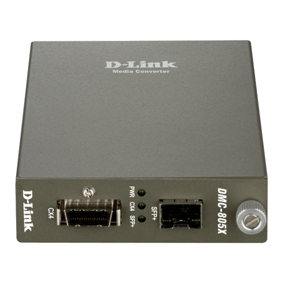
Page 8: Led Indicator
LED Indicator The LED indicators give you instant feedback on status of the converter: LEDs State Indication Lights on Power on (Power) Lights off Power off Lights on Linking Lights Blinking Data transmitting and receiving Lights off Not Linking Lights on Linking SPF+ Lights Blinking... -
Page 9: Link Pass Through Function
The LLCF setting is always Enable on this converter. The table below shows how LLCF function is working: DMC-805X #1 DMC-805X #2 Link2 Link3 Link4... -
Page 10: Media Converter
There is a switch to enable or disable the function of the media converter. The table below shows how LLR function is working: Media Converter DMC-805X #1 DMC-805X #2 Link2 Link3 Link5 Link4... - Page 11 Switch There is one pin DIP switch on the module which defines as switch 1: Switch 1: LLR When the switch was turned to “On”, it means that the LLR was enabled and “Off” for disabled. Note: When using two converters, don’t enable the both devices’ LLR function at the same time.
-
Page 12: Specifications
Specifications Standards: IEEE802.3ak 10GBASE-CX4 IEEE802.3ae/aq 10GBASE-SR/ER/LR/LRM/ZR Data Transfer Rate: 20Gbps Duplex Mode: Full Duplex Mode LED indicators: PWR, CX4, SFP+ Supported SFP+ DEM-431XT: Transceivers 10GBASE-SR SFP+ Transceiver (w/o DDM), 80m: OM1 & OM2 MMF,300m: OM3 MMF DEM-431XT-DD: 10GBASE-SR SFP+ Transceiver (with DDM), 80m: OM1 &... - Page 13 CX4 Cable 10GBASE-CX4 XAUI 4-lane PCS (Clause 48) and copper cabling similar to that used by InfiniBand technology, up to 15m DIP Switch Bit 1: Off: LLR disable(default) On: LLR enable Dimensions L120 × W88 × H25 mm Power External power adapter 12V/0.5A Temperture: Storage: -10°C ~ 70°C (14 ~ 158º...
- Page 14 Notes...
- Page 15 Notes...
- Page 16 Ver. 1.00(WW) 2012/03/29 29071600DM805X0...