Table of Contents
Advertisement
Quick Links
In the interests of user-safety (Required by safety regulations in some countries) the set should be restored to its
original condition and only parts identical to those specified should be used.
» ELECTRICAL SPECIFICATIONS ......................................................................................................... 1
» IMPORTANT SERVICE SAFETY PRECAUTION ................................................................................ 2
» LOCATION OF USER'S CONTROL ..................................................................................................... 6
» INSTALLATION AND SERVICE INSTRUCTIONS ................................................................................ 7
» CHASSIS LAYOUT ............................................................................................................................. 13
» BLOCK DIAGRAM ............................................................................................................................. 14
» SCHEMATIC DIAGRAMS ................................................................................................................... 15
» PRINTED WIRING BOARD ASSEMBLIES ........................................................................................ 23
» REPLACEMENT PARTS LIST............................................................................................................ 27
» PACKING OF THE SET ..................................................................................................................... 36
POWER INPUT ................................................... 120 V AC 60 Hz
POWER RATING ................................................................... 126W
PICTURE SIZE ......................................... 2,187 cm
CONVERGENCE ............................................................. Magnetic
SWEEP DEFLECTION ..................................................... Magnetic
FOCUS ............................................... Hi-Bi-Potential Electrostatic
INTERMEDIATE FREQUENCIES
Picture IF Carrier Frequency ..................................... 45.75 MHz
Sound IF Carrier Frequency ...................................... 41.25 MHz
Color Sub-Carrier Frequency ..................................... 42.17 MHz
AUDIO POWER
OUTPUT RATING .............. 1.3W + 1.3W (at 10% distortion and
SHARP CORPORATION
SERVICE MANUAL
MODELS
CONTENTS
ELECTRICAL SPECIFICATIONS
SPEAKER
SIZE ...................................................................... 8 cm (Round)
VOICE COIL IMPEDANCE ............................... 8 ohm at 400 Hz
2
(339 sq inch)
ANTENNA INPUT IMPEDANCE
VHF/UHF .................................................... 75 ohm Unbalanced
TUNING RANGES
VHF-Channels .............................................................. 2 thru 13
UHF-Channels ............................................................ 14 thru 69
CATV Channels .......................................................... 1 thru 125
(Nominal)
Dual CH Operate)
Specifications are subject to change without
prior notice.
This document has been published to be used for after
sales service only.
The contents are subject to change without notice.
1
COLOR TELEVISION
Chassis No. SN-81A
27N-S300
CN27S30
27N-S300
CN27S30
S20X227N-S300
Page
(EIA, Channel Plan U.S.A.)
Advertisement
Table of Contents

Related Manuals for Sharp 27N-S300


Summary of Contents for Sharp 27N-S300
-
Page 1: Table Of Contents
27N-S300 CN27S30 SERVICE MANUAL S20X227N-S300 COLOR TELEVISION Chassis No. SN-81A 27N-S300 CN27S30 MODELS In the interests of user-safety (Required by safety regulations in some countries) the set should be restored to its original condition and only parts identical to those specified should be used. -
Page 2: Important Service Safety Precaution
27N-S300 CN27S30 IMPORTANT SERVICE SAFETY PRECAUTION Service work should be performed only by qualified service technicians who are throughly familiar with all safety checks and the servicing guidelines which follow: WARNING X-RADIATION AND HIGH VOLTAGE LIMITS 1. For continued safety, no modification of any circuit 1. -
Page 3: Safety Notice
27N-S300 CN27S30 IMPORTANT SERVICE SAFETY PRECAUTION (Continued) • Connect the resistor connection to all exposed metal BEFORE RETURNING THE RECEIVER parts having a return to the chassis (antenna, metal (Fire & Shock Hazard) cabinet, screw heads, knobs and control shafts, Before returning the receiver to the user, perform escutcheon and etc.) and measure the AC voltage... - Page 4 27N-S300 CN27S30 PRECAUTIONS A PRENDRE LORS DE LA REPARATION Ne peut effectuer la réparation qu' un technicien spécialisé qui s'est parfaitement accoutumé à toute vérification de sécurité et aux conseils suivants. AVERTISSEMENT LIMITES DES RADIATIONS X ET DE LA HAUTE TENSION 1.
- Page 5 27N-S300 CN27S30 PRECAUTIONS A PRENDRE LORS DE LA REPARATION (Suite) • Toucher avec la sonde d'essai les pièces métalliques VERIFICATIONS CONTRE L'INCEN-DIE ET exposées qui présentent une voie de retour au LE CHOC ELECTRIQUE châssis (antenne, coffret métallique, tête des vis, Avant de rendre le récepteur à...
-
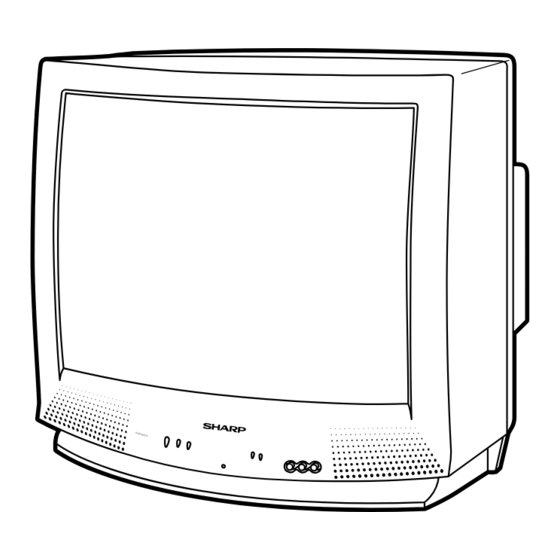
Page 6: Location Of User's Control
27N-S300 CN27S30 LOCATION OF USER'S CONTROL Front Panel POWER Press → On. Press again → Off. VOLUME UP/DOWN POWER – VOL + (+) Increases sound. (–) Decreases sound. POWER – VOL + SENSOR AREA FOR REMOTE CONTROL CHANNEL UP/DOWN ( ) Selects next higher channel. -
Page 7: Installation And Service Instructions
27N-S300 CN27S30 INSTALLATION AND SERVICE INSTRUCTIONS Note: (1) When performing any adjustments to resistor controls and transformers use non-metallic screwdrivers or TV alignment tools. (2) Before performing adjustments, the TV set must be on at least 15 minutes. CIRCUIT PROTECTION HIGH VOLTAGE CHECK The receiver is protected by a 4.0A fuse... - Page 8 27N-S300 CN27S30 For adjustments of this model, the bus data is converted to various analog signals by the D/A converter circuit. Note: There are still a few analog adjustments in this series such as focus and master screen voltage. Follow the steps below whenever the service adjustment is required. See "Table-B" to determine, if serv- ice adjustments are required.
- Page 9 27N-S300 CN27S30 DATA SERVICE ADJUSTMENT ITEM ADJUSTMENT CONTENTS NUMBER RANGE INITIAL VALUE PICTURE 00-7F TINT 00-7F COLOR 00-7F BRIGHTNESS 00-7F SHARPNESS 00-3F Must be set to "24" VERTICAL PHASE 00-07 Must be set to "00" HORIZONTAL PHASE 00-1F RF-AGC 00-3F...
-
Page 10: Service Adjustment
27N-S300 CN27S30 SERVICE ADJUSTMENT White Balance Adjustment VCO Adjustment 1. Receive a good local channel. 1. Connect a digital voltmeter between pin (44) of IC201 and ground. 2. Enter the service mode and select the service 2. Receive a good local channel. - Page 11 27N-S300 CN27S30 Sub-Brightness Adjustment 3.58MHz Trap Adjustment 1. Receive a good local channel. 1. Receive a good local channel. 2. Make sure the customer brightness control is set to 2. Enter the service mode and select the service center position.
-
Page 12: Mts Adjustment
27N-S300 CN27S30 MTS ADJUSTMENT P-IN-P ADJUSTMENT P-IN-P Y LEVEL Adjustment MTS Level Adjustment 1. Receive a good local channel. 1. Feed the following monaural signal to pin (14) of 2. Enter the service mode and select the service IC3001. Monaural signal : 300Hz, 245mVrms adjustment "P01". -
Page 13: Chassis Layout
27N-S300 CN27S30 CHASSIS LAYOUT PWB-H PWB-B PWB-R PWB-A... -
Page 14: Block Diagram
27N-S300 CN27S30 BLOCK DIAGRAM... -
Page 15: Description Of Schematic Diagram
27N-S300 CN27S30 DESCRIPTION OF SCHEMATIC DIAGRAM WAVEFORM MEASUREMENT CONDITIONS: NOTES: 1. Photographs taken on a standard gated color bar 1. The unit of resistance "ohm" is omitted. signal, the tint setting adjusted for proper color. The (K=k Ω =1000 Ω , M=M Ω ) wave shapes at the red, green and blue cathodes of 2. - Page 16 27N-S300 27N-S300 CN27S30 CN27S30 SCHEMATIC DIAGRAM: MAIN-1 Unit 16~17...
- Page 17 27N-S300 27N-S300 CN27S30 CN27S30 SCHEMATIC DIAGRAM: MAIN-2 Unit 18~19...
- Page 18 27N-S300 27N-S300 CN27S30 CN27S30 SCHEMATIC DIAGRAM: P-IN-P Unit 20~21...
- Page 19 27N-S300 CN27S30 SCHEMATIC DIAGRAM: CRT and FRONT AV Units...
-
Page 20: Printed Wiring Board Assemblies
27N-S300 CN27S30 PRINTED WIRING BOARD ASSEMBLIES PWB-B: CRT Unit (Wiring Side) PWB-H: FRONT AV Unit (Wiring Side) - Page 21 27N-S300 CN27S30 PWB-A: MAIN Unit (Wiring Side)
- Page 22 27N-S300 CN27S30 PWB-A: MAIN Unit (Chip Parts Side)
- Page 23 27N-S300 CN27S30 PWB-R : P-IN-P Unit (Wiring Side) PWB-R : P-IN-P Unit (Chip Parts Side)
-
Page 24: Parts List
4. DESCRIPTION in USA: Contact your nearest SHARP Parts Distributor to order. in CANADA: Contact SHARP Electronics of Conada Limited For location of SHARP Parts Distributor, Please call Toll- Phone (416) 890-2100 Free; 1-800-BE-SHARP MARQUE: SECTION LIVRAISON DES PIECES DE RECHANGE... - Page 25 27N-S300 CN27S30 Ref. No. Part No. Description Code Ref. No. Part No. Description Code å D702 RH-DX0154CEZZ J Diode PWB-A: DUNTKA120WE K0/1 MAIN UNIT (Continued) RH-DX0259CEZZ å D703 RH-DX0154CEZZ J Diode Q403 VS2SD601AR/-1 J 2SD601AR Q421 VS2SB709AR/-1 J 2SB709AR RH-DX0259CEZZ...
- Page 26 27N-S300 CN27S30 Ref. No. Part No. Description Code Ref. No. Part No. Description Code PWB-A: DUNTKA120WE C505 VCQYTA1HM473K J 0.047 50V Mylar K0/1 C507 VCQYTA1HM103K J 0.01 Mylar MAIN UNIT (Continued) C508 VCEA0A1VW107M J 100 C509 VCKYCY1HB182K J 1800p 50V...
- Page 27 27N-S300 CN27S30 Ref. No. Part No. Description Code Ref. No. Part No. Description Code RJ43 VRS-CY1JF000J 1/16W M-Ox. PWB-A: DUNTKA120WE K0/1 RJ45 VRD-MN2BE000J 1/8W Carbon MAIN UNIT (Continued) RJ47 VRD-MN2BE000J 1/8W Carbon RJ48 VRD-MN2BE000J 1/8W Carbon C928 VCKYCY1HB103K J 0.01...
- Page 28 27N-S300 CN27S30 Ref. No. Part No. Description Code Ref. No. Part No. Description Code å R708 VRD-RM2HD330J J 33 1/2W Carbon PWB-A: DUNTKA120WE K0/1 å R709 VRS-KA3NG331K M 330 7W M-Ox. MAIN UNIT (Continued) å R710 VRD-RM2HD330J J 33 1/2W Carbon å...
- Page 29 27N-S300 CN27S30 Ref. No. Part No. Description Code Ref. No. Part No. Description Code SWITCHES PWB-A: DUNTKA120WE K0/1 S2501 QSW-K0202PEZZ R Power MAIN UNIT (Continued) S2502 QSW-K0202PEZZ R Vol-down S2503 QSW-K0202PEZZ R Vol-up R2006 VRS-CY1JF102J J 1k 1/16W M-Ox. S2504 QSW-K0202PEZZ...
-
Page 30: Crt Unit
27N-S300 CN27S30 Ref. No. Part No. Description Code Ref. No. Part No. Description Code PWB-B: DUNTK9510WEK0 PWB-C: DUNTK9310WEK1 FRONT AV UNIT CRT UNIT MISCELLANEOUS PARTS TRANSISTORS J1001 QJAKE0053GEZZ J Jack, Video in Q851 VS2SC3198-Y-1 J 2SC3198(Y) J1002 QJAKE0055GEZZ J Jack, Audio in (L) - Page 31 27N-S300 CN27S30 Ref. No. Part No. Description Code Ref. No. Part No. Description Code PWB-R: DUNTK9511WEK3 R1723 VRS-CY1JF822J J 8.2k 1/16W M-Ox. R1724 VRS-CY1JF222J J 2.2k 1/16W M-Ox. P-IN-P UNIT (Continued) R1741 VRD-RA2BE102J J 1k 1/8W Carbon R1742 VRS-CY1JF102J J 1k 1/16W M-Ox.
-
Page 32: Miscellaneous Parts
GCABB1131MEKA M Rear Cabinet VSP0080PBK98A M Speaker 8 ohm, (R) VSP0080PBK98A M Speaker 8 ohm, (L) SUPPLIED ACCESORRIES RRMCG1396CESA M Infrared R/C Unit TGAN-1006MEZZ M Guarantee Card (27N-S300) AA TiNS-6921MEZZ M Operation Manual (27N-S300) TiNS-6969MEZZ M Operation Manual (CN27S30) CABINET PARTS LOCATION... -
Page 33: Packing Of The Set
27N-S300 CN27S30 Ref. No. Part No. Description PACKING OF THE SET Code Ref. No. Part No. Description Code Polyethylene Bag Operation Manual Guarantee Card Infrared R/C Unit Batteries Wrapping Sheet Buffer Material FRONT Packing Case Use tapes to fix the packing case. - Page 34 27N-S300 CN27S30 Ref. No. Part No. Description Code Ref. No. Part No. Description Code...
- Page 35 Code Ref. No. Part No. Description Code COPYRIGHT © 2000 BY SHARP CORPORATION ALL RIGHTS RESERVED. No part of this publication may be reproduced, stored in a retrieval system, or transmitted in any form or by any means, electronic, mechanical, photocopying, recording, or otherwise, without prior written permission of the publisher.