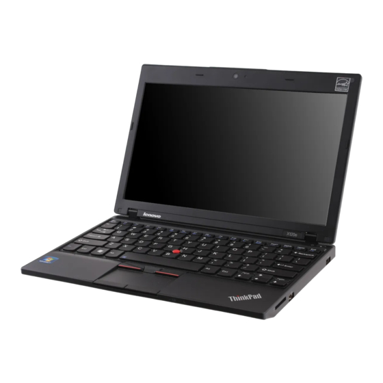
Lenovo THINKPAD X120E Hardware Maintenance Manual
Lenovo laptop user manual
Hide thumbs
Also See for THINKPAD X120E:
- Brochure & specs (5 pages) ,
- Инструкции по начальной установке (2 pages) ,
- Setup manual (2 pages)
Table of Contents
Advertisement
Advertisement
Table of Contents

Related Manuals for Lenovo THINKPAD X120E


Summary of Contents for Lenovo THINKPAD X120E
- Page 1 ThinkPad X100e and X120e Hardware Maintenance Manual...
- Page 2 Third Edition (February 2011) © Copyright Lenovo 2009, 2011. LENOVO products, data, computer software, and services have been developed exclusively at private expense and are sold to governmental entities as commercial items as defined by 48 C.F.R. 2.101with limited and restricted rights to use, reproduction and disclosure.
-
Page 3: Table Of Contents
1100 CRT board assembly (with cable) ..1110 Speaker assembly ... 1120 I/O board (for ThinkPad X120e) ..1130 System board, fan assembly, and backup battery . - Page 4 Chapter 9. Locations ..89 Front view ....Rear view....Bottom view .
-
Page 5: About This Manual
Important: This manual is intended only for trained service technicians who are familiar with ThinkPad products. Use this manual along with the advanced diagnostic tests to troubleshoot problems effectively. Before servicing a ThinkPad product, be sure to read all the information under Chapter 1 “Safety information” on page 1. © Copyright Lenovo 2009, 2011... - Page 6 ThinkPad X100e and X120e Hardware Maintenance Manual...
-
Page 7: Chapter 1. Safety Information
• Reinstall all covers correctly before returning the machine to the customer. • Fan louvers on the machine help to prevent overheating of internal components. Do not obstruct fan louvers or cover them with labels or stickers. © Copyright Lenovo 2009, 2011... -
Page 8: Electrical Safety
Electrical safety Observe the following rules when working on electrical equipment. Important: Use only approved tools and test equipment. Some hand tools have handles covered with a soft material that does not insulate you when working with live electrical currents. Many customers have, near their equipment, rubber floor mats that contain small conductive fibers to decrease electrostatic discharges. -
Page 9: Safety Inspection Guide
– Use caution; do not become a victim yourself. – Switch off power. – Send another person to get medical aid. Safety inspection guide The purpose of this inspection guide is to assist you in identifying potentially unsafe conditions. As each machine was designed and built, required safety items were installed to protect users and service technicians from injury. -
Page 10: Grounding Requirements
Make sure that the ESD protective devices you use have been certified (ISO 9000) as fully effective. When handling ESD-sensitive parts: • Keep the parts in protective packages until they are inserted into the product. • Avoid contact with other people. •... - Page 11 Some standby batteries contain a small amount of nickel and cadmium. Do not disassemble a standby battery, recharge it, throw it into fire or water, or short-circuit it. Dispose of the battery as required by local ordinances or regulations. Use only the battery in the appropriate parts listing. Use of an incorrect battery can result in ignition or explosion of the battery.
- Page 12 Unless hot swap is allowed for the FRU being replaced, do as follows before removing it: power off the computer, unplug all power cords from electrical outlets, remove the battery pack, and disconnect any interconnecting cables. ThinkPad X100e and X120e Hardware Maintenance Manual...
- Page 13 PERIGO Antes de ligar o computador após a substituição da FRU, certifique-se de que todos os parafusos, molas e outras peças pequenas estejam no lugar e não estejam soltos dentro do computador. Verifique isso sacudindo o computador e procurando ouvir sons de peças soltas. Peças metálicas ou lascas de metal podem causar curto-circuito.
- Page 14 A bateria de lítio pode causar incêndio, explosão ou graves queimaduras. Não a recarregue, remova seu conector polarizado, desmonte-a, aqueça-a acima de 100°C (212°F), incinere-a, ou exponha o conteúdo de sua célula à água. Descarte a bateria conforme requerido pelas leis ou regulamentos locais. Use somente a bateria nas partes listadas apropriadas.
- Page 15 Certaines batteries de secours contiennent du nickel et du cadmium. Ne les démontez pas, ne les rechargez pas, ne les exposez ni au feu ni à l'eau. Ne les mettez pas en court-circuit. Pour les mettre au rebut, conformez-vous à la réglementation en vigueur. Lorsque vous remplacez la pile de sauvegarde ou celle de l'horloge temps réel, veillez à...
- Page 16 DANGER Si le remplacement à chaud n'est pas autorisé pour l'unité remplaçable sur site que vous remplacez, procédez comme suit avant de retirer l'unité : mettez l'ordinateur hors tension, débranchez tous les cordons d'alimentation des prises de courant, retirez le bloc de batterie et déconnectez tous les câbles d'interconnexion.
- Page 17 Die Leuchtstoffröhre im LCD-Bildschirm enthält Quecksilber. Bei der Entsorgung die örtlichen Bestimmungen für Sondermüll beachten. Der LCD-Bildschirm besteht aus Glas und kann zerbrechen, wenn er unsachgemäß behandelt wird oder der Computer auf den Boden fällt. Wenn der Bildschirm beschädigt ist und die darin befindliche Flüssigkeit in Kontakt mit Haut und Augen gerät, sollten die betroffenen Stellen mindestens 15 Minuten mit Wasser abgespült und bei Beschwerden anschließend ein Arzt aufgesucht werden.
- Page 18 ThinkPad X100e and X120e Hardware Maintenance Manual...
- Page 19 Chapter 1 Safety information...
- Page 20 Antes de encender el sistema despues de sustituir una FRU, compruebe que todos los tornillos, muelles y demás piezas pequeñas se encuentran en su sitio y no se encuentran sueltas dentro del sistema. Compruébelo agitando el sistema y escuchando los posibles ruidos que provocarían. Las piezas metálicas pueden causar cortocircuitos eléctricos.
- Page 21 Las baterías contienen pequeñas cantidades de níquel. No las desmonte, ni recargue, ni las eche al fuego o al agua ni las cortocircuite. Deséchelas tal como dispone la normativa local. Utilice sólo baterías que se encuentren en la lista de piezas al sustituir la batería. La utilización de una batería no apropiada puede provocar la ignición o explosión de la misma.
- Page 22 ThinkPad X100e and X120e Hardware Maintenance Manual...
-
Page 23: Chapter 2. Important Service Information
Important: BIOS and device driver fixes are customer-installable. The BIOS and device drivers are posted on the customer support site http://www.lenovo.com/support. System Disassembly/Reassembly videos that show the FRU removals or replacements for the Lenovo® authorized service technicians are available in the following support site: http://www.lenovoservicetraining.com/ion/... -
Page 24: Strategy For Replacing A Hard Disk Drive
Dynamic Configure To Order (CTO) This provides the ability for a customer to configure an IBM® or a Lenovo solution from an eSite, and have this configuration sent to fulfillment, where it is built and shipped directly to the customer. The machine label, Product Entitlement Warehouse (PEW), eSupport, and the HMM will load these products as the 4-digit MT and 3-digit model, where model = “CTO”... -
Page 25: Fru Identification For Cto, Cmv, And Gav Products
• eSupport can be used to view the list of key commodities built in a particular machine serial (this is the same record found in PEW). • eSupport can be accessed at the Web site http://www.lenovo.com/support. • To view the key commodities, click on PARTS INFORMATION, then PARTS LOOKUP. Type in the model type and serial number. - Page 26 ThinkPad X100e and X120e Hardware Maintenance Manual...
-
Page 27: Chapter 3. General Checkout
“Diagnostics using PC-Doctor for DOS” on page 22 – “Testing the computer” on page 23 – “Detecting system information with PC-Doctor” on page 24 – “Lenovo ThinkVantage Toolbox” on page 25 – “FRU tests” on page 25 • “Power system checkout” on page 26 –... -
Page 28: Checkout Guide
PC-Doctor. Note: PC-Doctor for DOS is available at the Web site http://www.lenovo.com/support. To create the PC-Doctor diagnostic CD, follow the instructions on the Web site. For some possible configurations of the computer, PC-Doctor might not run correctly. To avoid this problem, you need to initialize the computer BIOS setup before you run PC-Doctor. -
Page 29: Testing The Computer
3. On the BIOS Setup Utility (ThinkPad Setup for ThinkPad X120e) screen, press F9, Enter, F10, and then press Enter. Note: When you initialize the computer configuration, some devices are disabled, such as the serial port. - Page 30 Diagnostics Run Normal Test Run Quick Test CPU/Coprocessor Systemboard Video Adapter Fixed Disks Diskette Drives Other Devices Communication Wireless LAN Advanced Memory Tests PC-DOCTOR 2.0 Copyright 2008 PC-Doctor, Inc. All Rights Reserved. Use the cursor keys and ESC to move in menus. Press ENTER to select. The options on the test menu are as follows: Diagnostics •...
-
Page 31: Lenovo Thinkvantage Toolbox
To run this program, do as follows: For Windows 7: Click Start ➙ Control Panel ➙ System and Security ➙ Lenovo’s System Health and Diagnostics (Lenovo - System Health and Diagnostics for ThinkPad X120e). For Windows Vista and Windows XP: Click Start ➙... -
Page 32: Power System Checkout
If the Touch Pad does not work, check the configuration as specified in the BIOS Setup Utility (ThinkPad Setup for ThinkPad X120e). If the Touch Pad is disabled, select Automatic to enable it. If enabling the Touch Pad does not correct the problem, continue with the following: •... -
Page 33: Checking The Ac Adapter
• “Checking operational charging” on page 27 • “Checking the battery pack” on page 27 • “Checking the backup battery” on page 28 Checking the ac adapter You are here because the computer fails only when the ac adapter is used. •... -
Page 34: Checking The Backup Battery
is displayed. To get detailed information about the battery, double-click the Power Manager Battery Gauge icon. Note: If the battery pack becomes hot, it may not be able to charge. Remove it from the computer and leave it at room temperature for a while. After it cools down, reinstall and recharge it. To check the battery pack, do the following: 1. -
Page 35: Chapter 4. Related Service Information
F1 key. The Setup Utility program opens. b. Use the arrow keys to select Startup ➙ Boot. c. Select the CD/DVD drive as the 1st Boot Device. 2. Insert the Operating System Recovery Disc into the DVD drive. © Copyright Lenovo 2009, 2011... -
Page 36: Passwords
3. Press F10 to save the Setup Utility configuration changes. Follow the instructions on the screen to begin the recovery process. 4. Select your language and click Next. 5. Read the license. If you agree with the terms and conditions, select I accept these terms and conditions and then click Next. -
Page 37: Supervisor Password
A supervisor password (SVP) protects the system information stored in the BIOS Setup Utility (ThinkPad Setup for ThinkPad X120e). The user must enter the SVP in order to get access to the BIOS Setup Utility or ThinkPad Setup and change the system configuration. -
Page 38: Power Management
1. Turn on the computer. 2. When the ThinkPad logo comes up, immediately press F1 to enter BIOS Setup Utility (ThinkPad Setup for ThinkPad X120e). 3. Select Security, using the cursor directional keys to move down the menu. 4. Select Password. -
Page 39: Hibernation Mode
Also, in either of the following events, the computer automatically returns from sleep (standby) mode and resumes operation: • The ring indicator (RI) is signaled by a serial device or a PC Card device. ( does not support the ring indicator (RI) resume by PC Card device.) •... -
Page 40: Numeric Error Codes
System board. 1. Charge the battery pack. 2. Battery pack. 1. Run BIOS Setup Utility (ThinkPad Setup for ThinkPad X120e), and then save current setting by pressing F10. 2. System board. Change keyboard, and restart the computer. Run interactive tests of the keyboard and the auxiliary input device. - Page 41 1. Charge the backup battery for more than 8 hours by connecting the ac adapter. 2. Replace the backup battery and run BIOS Setup Utility (ThinkPad Setup for ThinkPad X120e) to reset the time and date. Turn off the computer and discharge CMOS. Then restart the computer.
-
Page 42: Error Messages
ThinkPad X100e and X120e Hardware Maintenance Manual FRU or action, in sequence Press F1 to enter BIOS Setup Utility (ThinkPad Setup for ThinkPad X120e). Press F9, and Enter to load the default setting. Then save the current setting by pressing F10, and restart the computer. -
Page 43: Intermittent Problems
If the LCD you are servicing has two or less visible defective pixels, it should not be considered faulty. However, if the LCD has three or more visible defective pixels, it will be deemed as defective by Lenovo and it should be replaced. - Page 44 d. Battery pack e. Hard disk drive f. External diskette drive or optical drive g. DIMM h. Optical disk or diskette in the internal drive i. PC Cards 4. Turn on the computer. 5. Determine whether the problem has been solved. 6.
-
Page 45: Chapter 5. Status Indicators
Green: Windows XP) status Blinking green: © Copyright Lenovo 2009, 2011 The computer is on and ready to use. The power switch stays lit whenever the computer is on and is not lit when the computer is in sleep (standby) mode. - Page 46 Table 6. Status indicators (continued) Indicator Meaning Battery status Green: Orange: Fast blinking orange: Slow blinking orange: Slow blinking green: Quick blinking orange: The battery status indicator is off: Note: If the computer is operating on battery power, the battery status indicator does not work while the computer is turned off or is in sleep (standby) mode or hibernation mode.
-
Page 47: Chapter 6. Fn Key Combinations
From the camera setting window, you can also change the setting of the microphone mute button. Notes: The camera settings area only appears if the computer has an integrated camera. If the computer is running Windows XP, it does not have the setting of the microphone mute button. © Copyright Lenovo 2009, 2011... - Page 48 Table 7. Fn key combinations (continued) Key combination Description Fn+F7 For Windows XP: Apply a presentation scheme directly, with no need to start Presentation Director. To disable this function and use the Fn+F7 key combination for switching a display output location, start Presentation Director, and change the settings.
- Page 49 Table 7. Fn key combinations (continued) Key combination Description Fn+Delete The computer display becomes dimmer. The purpose of this method is to change the brightness level temporarily. To change the default brightness level, change the settings of the Power Option in the Control Panel or use the Power Manager.
- Page 50 ThinkPad X100e and X120e Hardware Maintenance Manual...
-
Page 51: Chapter 7. Fru Replacement Notices
Never use a screw that you removed. Use a new one. Make sure that all of the screws are tightened firmly. • Ensure torque screw drivers are calibrated correctly following country specifications. © Copyright Lenovo 2009, 2011... -
Page 52: Retaining Serial Numbers
If you replace the system board, you must restore the serial number of the system unit to its original value. Before replacing the system board, save the original serial number by doing the following: 1. Install the LENOVO ThinkPad Hardware Maintenance Diskette Version 1.76 or later, and restart the computer. -
Page 53: Reading Or Writing The Eca Information
When you replace the system board, you must set the UUID on the new system board as follows: 1. Install the LENOVO ThinkPad Hardware Maintenance Diskette Version 1.76 or later, and restart the computer. 2. From the main menu, select 4. Assign UUID. A new UUID is created and written. If a valid UUID already exists, it is not overwritten. - Page 54 ThinkPad X100e and X120e Hardware Maintenance Manual...
-
Page 55: Chapter 8. Removing And Replacing A Fru
(ESD) strap (P/N 6405959). Before servicing ThinkPad X100e and ThinkPad X120e Some models of the ThinkPad X100e and ThinkPad X120e might have the SIM card that the customer has installed. If the computer you are servicing has the SIM card, remove it before you start the servicing. -
Page 56: 1010 Battery Pack
1010 Battery pack Important notice for replacing a battery pack: Lenovo ThinkVantage Toolbox have an automatic battery diagnostic that determines if the battery pack is defective. A battery pack FRU should not be replaced unless this diagnostic shows that the battery is defective. -
Page 57: 1020 Bottom Door
Table 8. Removal steps of battery pack DANGER Use only the battery specified in the parts list for your computer. Any other battery could ignite or explode. Unlock the battery latches . Holding the battery latches in the unlocked position, remove the battery pack in the direction shown by arrow When installing: Install the battery pack in the slot, and then make sure that the battery latch is in the locked position. - Page 58 Table 9. Removal steps of bottom door (continued) For ThinkPad X100e For ThinkPad X120e Applying labels to the bottom door For ThinkPad X100e The new bottom door FRU is shipped with a kit containing label. When you replace the bottom door,...
- Page 59 Windows license label (COA) For the location of each label, refer the following figure: For ThinkPad X120e The new bottom door FRU is shipped with a kit containing label. When you replace the bottom door, you need to apply the following labels:...
-
Page 60: 1030 Hard Disk Drive (Hdd)
Israel label China wireless LAN label For the location of each label, refer the following figure: 1030 Hard disk drive (HDD) For access, remove these FRUs in order: • “1010 Battery pack” on page 50 • “1020 Bottom door” on page 51 Attention: •... - Page 61 Table 10. Removal steps of HDD For ThinkPad X100e For ThinkPad X120e Step Screw (quantity) M2 × 7 mm, wafer-head, nylon-coated (1) Torque Color Silver 0.181 Nm (1.85 kgfcm) Chapter 8 Removing and replacing a FRU...
-
Page 62: 1040 Dimm
Table 10. Removal steps of HDD (continued) When installing: Make sure that the HDD connector is attached firmly. 1040 DIMM For access, remove these FRUs in order: • “1010 Battery pack” on page 50 • “1020 Bottom door” on page 51 Table 11. -
Page 63: 1050 Pci Express Mini Card For Wireless Lan
Table 11. Removal steps of DIMM (continued) Note: If the computer you are servicing has two DIMM slots and only one DIMM is used, the card must be installed in SLOT-0 ( ), but not in SLOT-1 ( When installing: Insert the notched end of the DIMM into the socket. Press the DIMM firmly, and pivot it until it snaps into the place. -
Page 64: 1060 Pci Express Mini Card For Wireless Wan
For ThinkPad X100e: Plug the gray cable into the jack marked MAIN or M, and the black cable into the jack marked AUX or A on the card. For ThinkPad X120e: Plug the white cable into the jack marked 1 or M, and the black cable into the jack marked 2 or A on the card. - Page 65 Table 13. Removal steps of PCI Express Mini Card for wireless WAN (continued) Step Screw (quantity) M2 × 3 mm, small-head, nylon-coated (1) Note: Plug the red cable into the jack marked MAIN, and the blue cable into the jack marked AUX on the card. Color Silver Chapter 8...
-
Page 66: 1070 Bluetooth Daughter Card (Bdc-2)
“1020 Bottom door” on page 51 Table 14. Removal steps of BDC-2 for ThinkPad X100e Step Screw (quantity) M2 × 3 mm, small-head, nylon-coated (1) For ThinkPad X120e: For access, remove these FRUs in order: • “1010 Battery pack” on page 50 •... -
Page 67: 1080 Keyboard
Table 15. Removal steps of BDC-2 for ThinkPad X120e Step Screw (quantity) M2 × 3 mm, small-head, nylon-coated (1) When installing: Make sure that the connector is attached firmly. 1080 Keyboard For access, remove these FRUs in order: • “1010 Battery pack” on page 50 •... - Page 68 Table 16. Removal steps of keyboard (continued) Step Screw (quantity) M2 × 3 mm, big-head, nylon-coated (2) For ThinkPad X120e Step Screw (quantity) M2 × 3 mm, big-head, nylon-coated (2) M2 × 7 mm, flat-head, nylon-coated (1) ThinkPad X100e and X120e Hardware Maintenance Manual...
- Page 69 Table 16. Removal steps of keyboard (continued) Chapter 8 Removing and replacing a FRU...
-
Page 70: 1090 Palm Rest Assembly, Power-On Board Assembly (With Cable), And Microphone
Table 17. Installation steps of keyboard When installing the keyboard, do as follows: 1. Attach the keyboard connectors. 2. Attach the keyboard so that the front edge of the keyboard are under the frame as shown in this figure. 3. Secure the keyboard by tightening the screws from the bottom side of the computer. 1090 Palm rest assembly, power-on board assembly (with cable), and microphone For access, remove these FRUs in order:... - Page 71 Table 18. Removal steps of palm rest assembly, power-on board assembly (with cable), and microphone (continued) Step Screw (quantity) M2 × 7 mm, wafer-head, nylon-coated (2) For ThinkPad X100e Color Silver Torque 0.181 Nm (1.85 kgfcm) Chapter 8 Removing and replacing a FRU...
- Page 72 Table 18. Removal steps of palm rest assembly, power-on board assembly (with cable), and microphone (continued) Step Screw (quantity) M2 × 6 mm, wafer-head, nylon-coated (2) For ThinkPad X120e M2 × 7 mm, wafer-head, nylon-coated (3) When installing: Make sure that the connectors are attached firmly. ThinkPad X100e and X120e Hardware Maintenance Manual...
- Page 73 Table 18. Removal steps of palm rest assembly, power-on board assembly (with cable), and microphone (continued) Step Screw (quantity) M2 × 3 mm, big-head, nylon-coated (2) Color Torque Black 0.181 Nm (1.85 kgfcm) Chapter 8 Removing and replacing a FRU...
-
Page 74: 1100 Crt Board Assembly (With Cable)
Table 18. Removal steps of palm rest assembly, power-on board assembly (with cable), and microphone (continued) When installing: Make sure that all the projections of the palm rest assembly are attached firmly to the guide holes of the base cover. 1100 CRT board assembly (with cable) For access, remove these FRUs in order: •... -
Page 75: 1110 Speaker Assembly
Table 19. Removal steps of CRT board assembly (with cable) When installing: Make sure that the connectors are attached firmly. Step Screw (quantity) M2 × 4 mm, wafer-head, nylon-coated (1) 1110 Speaker assembly For access, remove these FRUs in order: Color Silver Chapter 8... -
Page 76: 1120 I/O Board (For Thinkpad X120E)
Step Screw (quantity) M2 × 4 mm, wafer-head, nylon-coated (2) When installing: Make sure that the connector is attached firmly. 1120 I/O board (for ThinkPad X120e) For access, remove these FRUs in order: • “1010 Battery pack” on page 50 •... -
Page 77: 1130 System Board, Fan Assembly, And Backup Battery
Table 21. Removal steps of I/O board Step Screw (quantity) M2 × 4 mm, wafer-head, nylon-coated (1) When installing: Make sure that the connector is attached firmly. 1130 System board, fan assembly, and backup battery Important notices for handling the system board: When handling the system board, bear the following in mind. - Page 78 “1110 Speaker assembly” on page 69 • “1120 I/O board (for ThinkPad X120e)” on page 70 Table 22. Location of major sensitive components on the system board Following components soldered on the top side of the system board are extremely sensitive. When you service the system board, avoid any kind of rough handling.
- Page 79 Table 22. Location of major sensitive components on the system board (continued) For ThinkPad X120e Accelerometer chip for the HDD Active Protection System™ APU (Accelerated Processing Units) PCH (Platform Controller Hub) Chapter 8 Removing and replacing a FRU...
- Page 80 Table 23. Removal steps of system board, bluetooth daughter card, fan assembly, and backup battery For ThinkPad X100e Step Screw (quantity) M2 × 4 mm, wafer-head, nylon-coated (2) For ThinkPad X120e ThinkPad X100e and X120e Hardware Maintenance Manual Color Silver Torque 0.181 Nm...
- Page 81 Table 23. Removal steps of system board, bluetooth daughter card, fan assembly, and backup battery (continued) Step Screw (quantity) M2 × 4 mm, wafer-head, nylon-coated (2) When installing: Make sure that the connector is attached firmly. Color Torque Silver 0.181 Nm (1.85 kgfcm) Chapter 8 Removing and replacing a FRU...
- Page 82 Table 23. Removal steps of system board, bluetooth daughter card, fan assembly, and backup battery (continued) For ThinkPad X100e For ThinkPad X120e DANGER Use only the battery specified in the parts list for your computer. Any other battery could ignite or explode.
-
Page 83: 1140 Lcd Unit
“1100 CRT board assembly (with cable)” on page 68 • “1110 Speaker assembly” on page 69 • “1120 I/O board (for ThinkPad X120e)” on page 70 • “1130 System board, fan assembly, and backup battery” on page 71 Chapter 8 Removing and replacing a FRU... - Page 84 Table 24. Removal steps of LCD unit Step Screw (quantity) For ThinkPad X100e, M2 × 3 mm, wafer-head, nylon-coated (2) For ThinkPad X120e, M2 × 4 mm, wafer-head, nylon-coated (2) In step , release all of the antenna cables from the cable guides. When installing: •...
-
Page 85: 1150 Dc-In Cable And Base Cover Assembly
Table 24. Removal steps of LCD unit (continued) Step Screw (quantity) For ThinkPad X100e, M2 × 4 mm, wafer-head, nylon-coated (3) For ThinkPad X120e, M2.5 × 4 mm, wafer-head, nylon-coated (3) 1150 DC-in cable and base cover assembly For access, remove these FRUs in order: •... - Page 86 • “1110 Speaker assembly” on page 69 • “1120 I/O board (for ThinkPad X120e)” on page 70 • “1130 System board, fan assembly, and backup battery” on page 71 Table 25. Removal steps of DC-in cable and base cover assembly...
- Page 87 For ThinkPad X120e The new base cover FRU is shipped with a kit containing labels of several kinds. When you replace the base cover, you need to apply the following labels: SIM information label under door Information label under door Certified label under battery Following labels need to be peeled off from the old base cover, and need to be put on the new base cover.
-
Page 88: 2010 Lcd Bezel Assembly
2010 LCD bezel assembly For access, remove the following FRU: • “1010 Battery pack” on page 50 Table 26. Removal steps of LCD bezel assembly Step Screw (quantity) M2 × 4 mm, wafer-head, nylon-coated (2) ThinkPad X100e and X120e Hardware Maintenance Manual Color Torque 0.181 Nm... -
Page 89: 2020 Integrated Camera
Table 26. Removal steps of LCD bezel assembly (continued) 2020 Integrated camera For access, remove these FRUs, in order: • “1010 Battery pack” on page 50 • “2010 LCD bezel assembly” on page 82 Chapter 8 Removing and replacing a FRU... -
Page 90: 2030 Lcd Panel, Hinges, And Lcd Cable
“1100 CRT board assembly (with cable)” on page 68 • “1110 Speaker assembly” on page 69 • “1120 I/O board (for ThinkPad X120e)” on page 70 • “1130 System board, fan assembly, and backup battery” on page 71 • “2010 LCD bezel assembly” on page 82 Table 28. -
Page 91: Color Torque
Table 28. Removal steps of LCD panel, hinges, and LCD cable (continued) Step Screw (quantity) M2 × 4 mm, wafer-head, nylon-coated (6) Chapter 8 Torque Color Silver 0.181 Nm (1.85 kgfcm) Removing and replacing a FRU... -
Page 92: 2090 Antenna Kit And Lcd Rear Cover Assembly
“1100 CRT board assembly (with cable)” on page 68 • “1110 Speaker assembly” on page 69 • “1120 I/O board (for ThinkPad X120e)” on page 70 • “1130 System board, fan assembly, and backup battery” on page 71 ThinkPad X100e and X120e Hardware Maintenance Manual Color Torque 0.181 Nm... - Page 93 • “2010 LCD bezel assembly” on page 82 • “2030 LCD panel, hinges, and LCD cable” on page 84 Table 29. Removal steps of antenna kit and LCD rear cover assembly When installing: When you install the antenna kit, route the cables as shown in the figures below. As you route the cables, make sure that they are not subjected to any tension.
- Page 94 ThinkPad X100e and X120e Hardware Maintenance Manual...
-
Page 95: Chapter 9. Locations
Chapter 9. Locations This chapter presents the location of ThinkPad X120e features and hardware. Front view Integrated camera (for some models) Power switch Security keyhole (for X100e) Universal serial bus (USB) connector (for X120e) Universal serial bus (USB) connector 4-in-1 Media Card Reader slot Power status indicators Note: For the description of each indicator, see Chapter 5 “Status indicators”... -
Page 96: Rear View
Rear view Combo audio jack RJ-45 (Ethernet) connector Universal serial bus (USB) connector Universal serial bus (USB) connector (for X100e) High-definition multimedia interface (HDMI) port (for X120e) Security keyhole (for X120e) External monitor connector AC power connector Bottom view Battery pack latch Battery pack Built-in stereo speaker Bottom door... -
Page 97: Chapter 10. Parts List
These CRUs are isolated parts within the computer that are concealed by an access panel that is typically secured by more than two screws. Once the access panel is removed, the specific CRU is visible. • FRUs marked with are available as options. © Copyright Lenovo 2009, 2011... -
Page 98: Overall
Overall ThinkPad X100e and X120e Hardware Maintenance Manual... - Page 99 Table 30. Parts list—Overall FRU (Overall) LCD unit (see “LCD FRUs” on page 114.) Power-on board assembly (with cable) Palm rest assembly for ThinkPad X100e • 0022-CTO, 22x • 2876-CTO, 22x, 23x, 24x, 25x, 26x, 27x, 28x, 29x, 2Ax, 2Bx, 2Cx, 2Dx, 2Ex, 2Fx, 2Gx, 2Hx, 2Jx, 2Lx, 2Mx, 2Nx, 2Px, 2Qx, 2Rx, 2Sx, 2Tx, 2Ux, 2Vx, 2Wx, 2x,x, 2Yx, 2Zx, 32x, 33x, 33x, 34x, 34x, 35x, 36x, 37x, 38x, 39x, 3Ax, 3Bx, 3Cx, 3Dx, 3Ex, 3Fx, 3Mx, 3Nx, 3Px, 3Qx, 3Rx, 3Sx, 3Tx, 3Ux, 3Vx, 3Wx, 3x,x, 3Yx, 3Zx,...
- Page 100 Table 30. Parts list—Overall (continued) FRU (Overall) Palm rest assembly for ThinkPad X120e System board assembly, Intel Pineview • 3507-CTO System board assembly, AMD Athlon (DX10) • 0022-CTO, 22x • 2876-CTO, 22x, 23x, 24x, 25x, 26x, 27x, 28x, 29x, 2Ax, 2Bx, 2Cx, 2Dx, 2Ex,...
- Page 101 Table 30. Parts list—Overall (continued) FRU (Overall) System board assembly, AMD Turion Neo X2 L625 (DX10) • 0022-CTO • 2876-CTO, • 3506-CTO • 3508-CTO, System board assembly, AMD Turion Neo X2 L625 (DX9) • 0022-CTO • 2876-CTO, 6Qx, 72x, 73x, 74x, 76x, 77x, 78x, 79x, 7Ax, 7Bx, 7Cx, 7Dx, 7Ex, 7Fx, 7Gx, 7Hx, 7Jx, 7Kx, 7Lx, 7Mx, 7Nx, 7Px, 7Qx, 7Rx, 7Sx, 7Tx, 7Ux, 7Vx, 7Wx, 7Yx, 7Zx, 82x, 83x, 84x, 85x, 86x, 87x, 88x, 89x, 8Ax, 8Bx, 8Cx, 8Dx, 8Ex, 8Fx, 92x, 94x, 95x, 96x, 97x, 98x, 9Jx, 9Kx, 9Lx, 9Mx, 9Nx, 9Px, 9Rx, 9Sx, 9Zx,...
- Page 102 Table 30. Parts list—Overall (continued) FRU (Overall) SATA hard disk drive, 160 GB, 5,400 rpm • 0022-CTO • 2876-CTO, 22x, 25x, 26x, 29x, 2Ax, 2Cx, 2Dx, 2Hx, 2Jx, 2Lx, 2Mx, 2Qx, 2Rx, 2Ux, 2Wx, 2Yx, 36x, 4Fx, 4Gx, 4Hx, 4Jx, 4Kx, 4Lx, 4Mx, 4Nx, 4Px, 55x, 5Yx, 9Cx, 9Dx, 9Ex, 9Fx, 9Gx, 9Hx, 9Jx, 9Kx, 9Lx, 9Mx, 9Nx, 9Px, 9Qx, 9x,x, ADx, AEx •...
- Page 103 Table 30. Parts list—Overall (continued) FRU (Overall) SATA hard disk drive, 250 GB, 5,400 rpm • 0022-CTO, 22x • 2876-CTO, 23x, 27x, 28x, 2Bx, 2Ex, 2Fx, 2Nx, 2Sx, 2Vx, 2x,x, 2Zx, 33x, 33x, 34x, 34x, 35x, 37x, 38x, 39x, 3Mx, 3Nx, 3Px, 3Qx, 3Rx, 3Tx, 3Ux, 3Vx, 42x, 43x, 45x, 46x, 48x, 49x, 4Bx, 4Qx, 4Rx, 4Sx, 4Tx, 4Ux, 4Vx, 4x,x, 4Yx, 53x, 56x, 57x, 58x, 5Fx, 5Gx, 5Hx, 5Jx, 5Kx, 5Lx, 5Mx, 5Nx, 5Rx, 5Wx, 5x,x, 5Zx, 62x, 6Rx, 6Tx, 6Vx, 6Zx, 72x, 73x, 74x, 76x, 77x, 78x, 79x, 7Ax, 7Hx, 7Jx, 7Kx, 7Lx, 7Mx,...
- Page 104 Table 30. Parts list—Overall (continued) FRU (Overall) SATA hard disk drive, 250 GB, 5,400 rpm • 0022-CTO, 22x • 2876-CTO, 23x, 27x, 28x, 2Bx, 2Ex, 2Fx, 2Nx, 2Sx, 2Vx, 2x,x, 2Zx, 33x, 33x, 34x, 34x, 35x, 37x, 38x, 39x, 3Mx, 3Nx, 3Px, 3Qx, 3Rx, 3Tx, 3Ux, 3Vx, 42x, 43x, 45x, 46x, 48x, 49x, 4Bx, 4Qx, 4Rx, 4Sx, 4Tx, 4Ux, 4Vx, 4x,x, 4Yx, 53x, 56x, 57x, 58x, 5Fx, 5Gx, 5Hx, 5Jx, 5Kx, 5Lx, 5Mx, 5Nx, 5Rx, 5Wx, 5x,x, 5Zx, 62x, 6Rx, 6Tx, 6Vx, 6Zx, 72x, 73x, 74x, 76x, 77x, 78x, 79x, 7Ax, 7Hx, 7Jx, 7Kx, 7Lx, 7Mx,...
- Page 105 Table 30. Parts list—Overall (continued) FRU (Overall) SATA hard disk drive, 320 GB, 5,400 rpm • 0022-CTO • 2876-CTO, 24x, 2Gx, 2Px, 2Tx, 32x, 3Ax, 3Bx, 3Cx, 3Dx, 3Ex, 3Fx, 3Sx, 3Wx, 3x,x, 3Yx, 3Zx, 44x, 47x, 4Ax, 4Cx, 4Dx, 4Ex, 4Wx, 4Zx, 52x, 59x, 5Ax, 5Bx, 5Cx, 5Dx, 5Ex, 5Px, 5Qx, 5Sx, 5Tx, 5Ux, 5Vx, 63x, 64x, 6Qx, 6Sx, 6Ux, 6Wx, 6x,x, 6Yx, 7Bx, 7Cx, 7Dx, 7Ex, 7Fx, 7Gx, 7Qx, 7Rx, 7Sx, 7Tx, 7Ux, 7Vx, 7Yx, 7Zx, 82x, 83x, 84x, 88x, 8Ax, 8Bx, 8Cx, 97x, 98x, 99x, 9Rx, 9Sx, 9Tx, 9Ux, 9Vx, 9Wx,...
- Page 106 Table 30. Parts list—Overall (continued) FRU (Overall) SATA hard disk drive, 320 GB, 5,400 rpm • 0596-CTO, 28x, 2Bx, 2Ex, 2Gx, 2Jx, 2Wx, 2Xx • 0611-CTO, 26x • 0613-CTO SATA hard disk drive, 160 GB, 7,200 rpm • 0596-CTO • 0611-CTO •...
- Page 107 • 3508-CTO, 3Nx, 3Px, 3Qx, 77x, 78x, 79x • 0596-CTO • 0611-CTO • 0613-CTO I/O sub card for ThinkPad X120e DC-in cable for ThinkPad X100e DC-in cable for ThinkPad X120e Battery pack, Li-ion (3 cell, 2.2 Ah) 17 • 0022-CTO, 22x •...
- Page 108 Table 30. Parts list—Overall (continued) FRU (Overall) Battery pack, Li-ion (3 cell, 2.2 Ah) 17 • 0022-CTO, 22x • 2876-CTO, 2Px, 2Tx, 2x,x, 42x, 45x, 48x, 4Cx, 4Dx, 4Ex, 4Fx, 4Gx, 4Hx, 4Jx, 4Kx, 4Lx, 4Mx, 4Nx, 4Px, 4Qx, 4Rx, 4Sx, 4Tx, 4Ux, 4Vx, 5Yx, 5Zx, 6Tx, 9Qx, AFx •...
- Page 109 Table 30. Parts list—Overall (continued) FRU (Overall) Battery pack, Li-ion (6 cell, 2.6 Ah) 17+ • 0022-CTO • 2876-CTO, 22x, 23x, 24x, 25x, 26x, 27x, 28x, 29x, 2Ax, 2Bx, 2Cx, 2Dx, 2Ex, 2Fx, 2Gx, 2Hx, 2Jx, 2Lx, 2Mx, 2Nx, 2Qx, 2Rx, 2Sx, 2Ux, 2Vx, 2Wx, 2Yx, 2Zx, 32x, 33x, 33x, 34x, 34x, 35x, 36x, 37x, 38x, 39x, 3Ax, 3Bx, 3Cx, 3Dx, 3Ex, 3Fx, 3Mx, 3Nx, 3Px, 3Qx, 3Rx, 3Sx, 3Tx, 3Ux, 3Vx, 3Wx, 3x,x, 3Yx, 3Zx, 43x, 44x, 46x, 47x, 49x, 4Ax, 4Bx, 4Wx, 4x,x, 4Yx, 4Zx, 52x, 53x, 55x, 56x, 57x, 58x, 59x, 5Ax, 5Bx, 5Cx,...
- Page 110 Table 30. Parts list—Overall (continued) FRU (Overall) Battery pack, Li-ion (6 cell, 2.6 Ah) 17+ • 0022-CTO • 2876-CTO, 22x, 23x, 24x, 25x, 26x, 27x, 28x, 29x, 2Ax, 2Bx, 2Cx, 2Dx, 2Ex, 2Fx, 2Gx, 2Hx, 2Jx, 2Lx, 2Mx, 2Nx, 2Qx, 2Rx, 2Sx, 2Ux, 2Vx, 2Wx, 2Yx, 2Zx, 32x, 33x, 33x, 34x, 34x, 35x, 36x, 37x, 38x, 39x, 3Ax, 3Bx, 3Cx, 3Dx, 3Ex, 3Fx, 3Mx, 3Nx, 3Px, 3Qx, 3Rx, 3Sx, 3Tx, 3Ux, 3Vx, 3Wx, 3x,x, 3Yx, 3Zx, 43x, 44x, 46x, 47x, 49x, 4Ax, 4Bx, 4Wx, 4x,x, 4Yx, 4Zx, 52x, 53x, 55x, 56x, 57x, 58x, 59x, 5Ax, 5Bx, 5Cx,...
- Page 111 Table 30. Parts list—Overall (continued) FRU (Overall) Battery pack, Li-ion (6 cell, 2.6 Ah) 17+ • 0022-CTO • 2876-CTO, 22x, 23x, 24x, 25x, 26x, 27x, 28x, 29x, 2Ax, 2Bx, 2Cx, 2Dx, 2Ex, 2Fx, 2Gx, 2Hx, 2Jx, 2Lx, 2Mx, 2Nx, 2Qx, 2Rx, 2Sx, 2Ux, 2Vx, 2Wx, 2Yx, 2Zx, 32x, 33x, 33x, 34x, 34x, 35x, 36x, 37x, 38x, 39x, 3Ax, 3Bx, 3Cx, 3Dx, 3Ex, 3Fx, 3Mx, 3Nx, 3Px, 3Qx, 3Rx, 3Sx, 3Tx, 3Ux, 3Vx, 3Wx, 3x,x, 3Yx, 3Zx, 43x, 44x, 46x, 47x, 49x, 4Ax, 4Bx, 4Wx, 4x,x, 4Yx, 4Zx, 52x, 53x, 55x, 56x, 57x, 58x, 59x, 5Ax, 5Bx, 5Cx,...
- Page 112 3x,x, 44x, 45x, 48x, 4Bx, 4Gx, 4Hx, 4Qx, 4Sx, 4Vx, 4Yx, 5Jx, 5Lx, 64x, 66x, 69x, 6Cx, 6Fx, 6Jx, 6Mx, 6Ux, 6Vx, 6Zx, 74x, 75x, 77x, 7Ax, 7Dx, 96x, 99x, A4x, ACx Base cover assembly for ThinkPad X120e (black) ThinkPad X100e and X120e Hardware Maintenance Manual FRU no.
- Page 113 Table 30. Parts list—Overall (continued) FRU (Overall) Base cover assembly for ThinkPad X120e (white) Base cover assembly for ThinkPad X120e (Red) Bottom door assembly for ThinkPad X100e (black) • 0022-CTO, 22x • 2876-CTO, 23x, 25x, 26x, 27x, 28x, 2Fx, 2Gx, 2Hx, 2Jx, 2Ux, 2Vx, 33x, 33x, 34x,...
- Page 114 Bottom door assembly for ThinkPad X120e (red) Speaker assembly CRT board assembly (with cable) for ThinkPad X100e CRT board assembly (with cable) for ThinkPad X120e Backup battery for ThinkPad X100e Backup battery for ThinkPad X120e Thermal module for ThinkPad X100e, AMD Athlon •...
- Page 115 9Tx, 9Wx, A2x, A3x, A4x, A5x, A6x, A7x, AAx, AGx, AHx, AJx, AKx Thermal module for ThinkPad X100e, Intel Pineview • 3507-CTO Thermal module for ThinkPad X120e Bluetooth daughter card (BDC-2.1) • 0022-CTO, 22x • 2876-CTO, 22x, 23x, 24x, 25x, 26x, 27x, 28x, 29x, 2Ax, 2Bx, 2Cx, 2Dx, 2Ex, 2Fx,...
- Page 116 Table 30. Parts list—Overall (continued) FRU (Overall) Bluetooth daughter card (BDC-2.1) • 0022-CTO, 22x • 2876-CTO, 22x, 23x, 24x, 25x, 26x, 27x, 28x, 29x, 2Ax, 2Bx, 2Cx, 2Dx, 2Ex, 2Fx, 2Gx, 2Nx, 2Px, 2Sx, 2Tx, 2Vx, 2x,x, 2Zx, 32x, 33x, 33x, 34x, 34x, 35x, 36x, 37x, 38x, 39x, 3Ax, 3Bx, 3Cx, 3Dx, 3Ex, 3Fx, 3Mx, 3Nx, 3Px, 3Qx, 3Rx, 3Sx, 3Tx, 3Ux, 3Vx, 3Wx, 3x,x, 3Yx, 3Zx, 44x, 47x, 4Ax, 4Bx, 4Cx, 4Dx, 4Ex, 4Fx, 4Gx, 4Hx, 4Jx, 4Kx, 4Lx, 4Mx, 4Nx, 4Px, 4Qx, 4Rx, 4Sx, 4Tx, 4Ux, 4Vx, 4Wx, 4x,x, 4Yx, 4Zx,...
- Page 117 Table 30. Parts list—Overall (continued) FRU (Overall) ThinkPad 11b/g/n Wireless LAN Mini-PCI Express Adapter II • 0022-CTO, 22x • 2876-CTO, 22x, 23x, 24x, 25x, 26x, 27x, 28x, 29x, 2Ax, 2Bx, 2Cx, 2Dx, 2Ex, 2Fx, 2Hx, 2Jx, 2Lx, 2Mx, 2Nx, 2Qx, 2Rx, 2Sx, 2Ux, 2Vx, 2Wx, 2x,x, 2Yx, 2Zx, 32x, 35x, 36x, 37x, 38x, 39x, 3Qx, 3Rx, 3Sx, 3Tx, 3Ux, 3Vx, 3Wx, 3x,x, 3Yx, 3Zx, 42x, 43x, 44x, 45x, 46x, 47x, 48x, 49x, 4Ax, 4Bx, 4Cx, 4Dx, 4Ex, 4Fx, 4Gx, 4Hx, 4Jx, 4Kx, 4Lx, 4Mx, 4Nx, 4Px, 4Qx, 4Rx, 4Sx, 4Tx, 4Ux, 4Vx, 4Wx, 4x,x, 4Yx, 4Zx,...
- Page 118 Table 30. Parts list—Overall (continued) FRU (Overall) Intel WiFi Link 5100 • 0022-CTO • 2876-CTO • 3506-CTO • 3507-CTO • 3508-CTO Intel Centrino Advanced-N x, WiMAx, 6250, WW SKU • 0022-CTO • 2876-CTO, 2Gx, 2Px, 2Tx, 33x, 33x, 34x, 34x, 3Ax, 3Bx, 3Cx, 3Dx, 3Ex, 3Fx, 3Mx, 3Nx, 3Px, 59x, 5Ax, 5Bx, 5Cx, 5Dx, 5Ex, 5Jx, 5Kx, 5Lx, 5Mx, 7Bx, 7Cx, 7Dx, 7Ex, 7Fx, 7Gx, 7Lx, 7Mx, 7Nx, 7Px •...
- Page 119 Table 30. Parts list—Overall (continued) FRU (Overall) 2-GB DDR2-667 SDRAM SO-DIMM (PC2-5300) card • 0022-CTO, 22x • 2876-CTO, 22x, 23x, 24x, 26x, 27x, 28x, 2Ax, 2Bx, 2Dx, 2Ex, 2Fx, 2Gx, 2Jx, 2Mx, 2Nx, 2Px, 2Rx, 2Sx, 2Tx, 2Ux, 2Vx, 2Wx, 2x,x, 2Yx, 2Zx, 32x, 33x, 33x, 34x, 34x, 37x, 38x, 39x, 3Ax, 3Bx, 3Cx, 3Dx, 3Ex, 3Fx, 3Mx, 3Nx, 3Px, 3Qx, 3Rx, 3Sx, 3Wx, 3x,x, 3Yx, 3Zx, 42x, 43x, 44x, 45x, 46x, 47x, 48x, 49x, 4Ax, 4Bx, 4Cx, 4Dx, 4Ex, 4Fx, 4Gx, 4Hx, 4Jx, 4Kx, 4Lx, 4Mx, 4Nx, 4Px, 4Qx, 4Rx, 4Sx, 4Tx, 4Ux, 4Vx,...
-
Page 120: Lcd Frus
LCD FRUs ThinkPad X100e and X120e Hardware Maintenance Manual... - Page 121 • 0022-all • 2876-all • 3506-CTO • 3508-all LCD bezel assembly for ThinkPad X100e, Intel Pineview • 3507-CTO LCD bezel assembly for ThinkPad X120e Hinges for ThinkPad X100e 11.6-inch LCD • 0022-all • 2876-all • 3506-CTO • 3508-all Hinges for ThinkPad X100e 11.6-inch LCD •...
- Page 122 Table 31. Parts list—LCD FRUs (continued) No. FRU (LCD FRUs) Integrated camera for ThinkPad X120e LCD rear cover assembly (black) • 0022-CTO, 22x • 2876-CTO, 23x, 25x, 26x, 27x, 28x, 2Fx, 2Gx, 2Hx, 2Jx, 2Ux, 2Vx, 33x, 33x, 34x, 34x, 35x,...
- Page 123 • 0022-all • 2876-all • 3506-CTO • 3508-all LCD cable for ThinkPad X100e 10.1-inch LCD • 3507-CTO LCD cable for ThinkPad X120e LCD module, 11.6-inch HD LED-backlight • 0022-all • 2876-all • 3506-CTO • 3508-all LCD module, 11.6-inch HD LED-backlight •...
-
Page 124: Keyboard
Keyboard Table 32. Parts list—Keyboard Language Arabic Belgian Brazilian Portuguese Bulgarian Canadian French (058) Canadian French (Acnor) Czech Danish Dutch Finnish, Swedish French German Greek (U.S. English and Greek layout) Hebrew Hungarian Icelandic Italian Japanese Korean Latin American Spanish Norwegian Polish Portuguese Russian... -
Page 125: Ac Adapters
• M3 × 3.5 mm (silver), wafer head (6) • M2.5 × 6.5 mm (black), flat head (10) Screw kit for ThinkPad X120e: • M2 × 2 mm (silver), flat head (3) • M2 × 2.5 mm (black), flat head (3) •... -
Page 126: Recovery Discs
Table 36. Parts list—2-pin power cords Country or region Argentina • models -CTO, xxY Brazil • models -CTO, xxP Canada, U.S. • models -CTO, xxF, xxL, xxS, xxU Japan • models -CTO, xxE, xxJ Table 37. Parts list—3-pin power cords Country or region Australia, New Zealand •... -
Page 127: Windows 7 Starter (32 Bit) Dvds
• 2876-CTO, 36x • 3506-CTO • 3507-CTO • 3508-CTO, 22x, 24x, 25x, 2Bx, 2Cx, 5Ax, 5Bx, 68x, 69x, 6Ax, 6Bx, 6Cx, 6Dx, 6Lx, 6Mx, 6Nx Table 38. Parts list—Windows XP Home Edition (32 bit) recovery DVDs Language Brazilian Portuguese Czech Danish Dutch English... -
Page 128: Windows 7 Home Basic (32 Bit) Dvds
Table 39. Parts list—Windows 7 Starter (32 bit) recovery DVDs Language English English (for India) Russian Russian (English-enabled) Spanish Turkish Windows 7 Home Basic (32 bit) DVDs Windows 7 Home Basic (32 bit) is preinstalled as the operating system in the following models: •... -
Page 129: Windows 7 Professional (32 Bit) Dvds
• 0596-CTO, 22x • 0611-CTO • 0613-CTO Table 41. Parts list—Windows 7 Home Premium (32 bit) recovery DVDs Language Danish English English (for India) English, Finnish, and Swedish (in Sweden) English, French, German, and Italian (in Switzerland) English, French, German, and Dutch English, Traditional Chinese (for Hong Kong S.A.R.), and Simplified Chinese French German... -
Page 130: Common Service Tools
Table 42. Parts list—Windows 7 Professional (32 bit) recovery DVDs Language Brazilian Portuguese Czech Danish English English (for India) English, Finnish, and Swedish (in Sweden) English, French, German, and Dutch (in Belgium and Luxemburg) English, French, German, and Italian (in Switzerland) English, Traditional Chinese (for Hong Kong S.A.R.), and Simplified Chinese French German... - Page 131 USB cable USB floppy diskette drive for maintenance diskette USB floppy diskette drive tool kit Test card for integrated Smart Card LENOVO ThinkPad Hardware Maintenance Diskette Version 1.76 or later Note: Download the file from the Web site http://www.lenovo.com/spm. 93F2838 00P6967...
- Page 132 ThinkPad X100e and X120e Hardware Maintenance Manual...
-
Page 133: Appendix A. Notices
Lenovo representative for information on the products and services currently available in your area. Any reference to a Lenovo product, program, or service is not intended to state or imply that only that Lenovo product, program, or service may be used. Any functionally equivalent product, program, or service that does not infringe any Lenovo intellectual property right may be used instead. -
Page 134: European Union - Compliance To The Electromagnetic Compatibility Directive
Equipment according to European Standard EN 55022. The limits for Class B equipment were derived for typical residential environments to provide reasonable protection against interference with licensed communication devices. Trademarks The following terms are trademarks of Lenovo in the United States, other countries or both: Active Protection System Lenovo ThinkPad... - Page 136 Part Number: 63Y0640_02 Printed in (1P) P/N: 63Y0640_02 *63Y0640_02*...