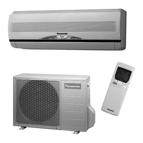
Panasonic CS-A7CKP Service Manual
Hide thumbs
Also See for CS-A7CKP:
- Service manual supplement (7 pages) ,
- Operating instructions manual (94 pages) ,
- Brochure (28 pages)
Table of Contents
Advertisement
CONTENTS
CS-A7CKP CU-A7CKP5
CS-A9CKP CU-A9CKP5
CS-A12CKP CU-A12CKP5
Page
2
3
6
12
14
15
16
17
39
44
© 2002 Matsushita Industrial Corp. Sdn. Bhd.
(11969-T). All rights reserved. Unauthorized copying
and distribution is a violation of law.
Order No. MAC0208024C8
Room Air Conditioner
Page
54
67
71
73
79
80
81
82
83
Advertisement
Table of Contents
Troubleshooting

Related Manuals for Panasonic CS-A7CKP


Summary of Contents for Panasonic CS-A7CKP
-
Page 1: Table Of Contents
Order No. MAC0208024C8 Room Air Conditioner CS-A7CKP CU-A7CKP5 CS-A9CKP CU-A9CKP5 CS-A12CKP CU-A12CKP5 CONTENTS Page Page 1 Features 11 2-way, 3-way Valve 2 Functions 12 Servicing Information 3 Product Specifications 13 Troubleshooting Guide 4 Dimensions 14 Technical Data 5 Refrigeration Cycle Diagram... -
Page 2: Features
CS-A7CKP CU-A7CKP5 / CS-A9CKP CU-A9CKP5 / CS-A12CKP CU-A12CKP5 1 Features • High Efficiency • Quality Improvement − Gas leakage protection • Compact Design − Prevent compressor reverse cycle − 2-stage OLP to protect compressor • Comfort Environment − Noise prevention during soft dry operation. -
Page 3: Functions
CS-A7CKP CU-A7CKP5 / CS-A9CKP CU-A9CKP5 / CS-A12CKP CU-A12CKP5 2 Functions Remote Control Self illuminating button OFF / ON I TEMP. Operation OFF / ON Room Temperature Setting Heating, Cooling, Soft Dry Operation. • Temperature Setting (16°C to 30°C) MODE Operation Mode Selection Automatic Operation •... -
Page 4: Indoor Unit
CS-A7CKP CU-A7CKP5 / CS-A9CKP CU-A9CKP5 / CS-A12CKP CU-A12CKP5 Indoor Unit AUTO OFF / ON Automatic Operation Button Ionizer Control • Ionizer control for generate negative ion in • Press for < 5s to operate Automatic discharge air. operation mode. (Used when the remote control cannot be used.) Indoor Fan Speed Control •... - Page 5 CS-A7CKP CU-A7CKP5 / CS-A9CKP CU-A9CKP5 / CS-A12CKP CU-A12CKP5 Outdoor Unit Compressor Reverse Rotation Deice Control Protection Control • To prevent frosting at outdoor heat exchanger. (Only for Heating Operation) • To protect compressor from reverse • Temperature of outdoor heat exchanger rotation when there is a instantaneous is sensed by TRS (Thermal Reed Switch).
-
Page 6: Product Specifications
CS-A7CKP CU-A7CKP5 / CS-A9CKP CU-A9CKP5 / CS-A12CKP CU-A12CKP5 3 Product Specifications Unit CS-A7CK CU-A7CK Power Source Phase, Voltage, Single, 220 - 230, 50 Hz Cycle Single, 220 - 240, 50 Hz Cooling Capacity kW (kcal/h) 2.00 - 2.05 (1,720 - 1,760) kW (BTU/h) 2.00 - 2.05 (6,820 - 6,990) - Page 7 CS-A7CKP CU-A7CKP5 / CS-A9CKP CU-A9CKP5 / CS-A12CKP CU-A12CKP5 Unit CS-A7CK CU-A7CK Air Circulation Type Cross-flow Fan Propeller Fan Material AS + Glass Fiber 20% PP Resin Motor Type Induction (4-poles) Induction (6-poles) Input 44.8 - 53.5 56 - 64 Rate...
- Page 8 CS-A7CKP CU-A7CKP5 / CS-A9CKP CU-A9CKP5 / CS-A12CKP CU-A12CKP5 Unit CS-A9CK CU-A9CK Power Source Phase, Voltage, Single, 220 - 230, 50 Hz Cycle Single, 220 - 240, 50 Hz Cooling Capacity kW (kcal/h) 2.65 - 2.70 (2,280 - 2,320) kW (BTU/h) 2.65 - 2.65 (9,040 - 9,040)
- Page 9 CS-A7CKP CU-A7CKP5 / CS-A9CKP CU-A9CKP5 / CS-A12CKP CU-A12CKP5 Unit CS-A9CK CU-A9CK Air Circulation Type Cross-flow Fan Propeller Fan Material AS + Glass Fiber 20% PP Resin Motor Type Induction (4-poles) Induction (6-poles) Input 44.8 - 53.5 56 - 64 Rate...
- Page 10 CS-A7CKP CU-A7CKP5 / CS-A9CKP CU-A9CKP5 / CS-A12CKP CU-A12CKP5 Unit CS-A12CK CU-A12CK Power Source Phase, Voltage, Single, 220 - 230, 50 Hz Cycle Single, 220 - 240, 50 Hz Cooling Capacity kW (kcal/h) 3.52 - 3.60 (3,030 - 3,100) kW (BTU/h) 3.52 - 3.57 (12,000 - 12,170)
- Page 11 CS-A7CKP CU-A7CKP5 / CS-A9CKP CU-A9CKP5 / CS-A12CKP CU-A12CKP5 Unit CS-A12CK CU-A12CK Cooling; 900 -900 — Speed Heating; 960 - 960 Medium Cooling; 1,120 - 1,120 — Heating; 1,120 - 1,120 High Cooling; 1,260 - 1,260 835 - 845 Heating; 1,300 - 1,300 Cooling;...
-
Page 12: Dimensions
CS-A7CKP CU-A7CKP5 / CS-A9CKP CU-A9CKP5 / CS-A12CKP CU-A12CKP5 4 Dimensions... - Page 13 CS-A7CKP CU-A7CKP5 / CS-A9CKP CU-A9CKP5 / CS-A12CKP CU-A12CKP5...
-
Page 14: Refrigeration Cycle Diagram
CS-A7CKP CU-A7CKP5 / CS-A9CKP CU-A9CKP5 / CS-A12CKP CU-A12CKP5 5 Refrigeration Cycle Diagram... -
Page 15: Block Diagram
CS-A7CKP CU-A7CKP5 / CS-A9CKP CU-A9CKP5 / CS-A12CKP CU-A12CKP5 6 Block Diagram... -
Page 16: Wiring Diagram
CS-A7CKP CU-A7CKP5 / CS-A9CKP CU-A9CKP5 / CS-A12CKP CU-A12CKP5 7 Wiring Diagram... -
Page 17: Operation Details
CS-A7CKP CU-A7CKP5 / CS-A9CKP CU-A9CKP5 / CS-A12CKP CU-A12CKP5 8 Operation Details 8.1. Cooling Mode Operation Cooling in operation according to Remote Control setting. Time Delay Safety Control (3 minutes) • When the compressor is stopped by Remote Control, it restarts after 3 minutes when it is turned ON by Remote Control. - Page 18 CS-A7CKP CU-A7CKP5 / CS-A9CKP CU-A9CKP5 / CS-A12CKP CU-A12CKP5 Compressor Protection Control • After the compressor starts for 50 seconds but the outdoor fan motor is still OFF, the compressor will stop and restart automatically. (Time Delay Safety Control is valid).
- Page 19 CS-A7CKP CU-A7CKP5 / CS-A9CKP CU-A9CKP5 / CS-A12CKP CU-A12CKP5 Cooling Operation Time Diagram...
- Page 20 CS-A7CKP CU-A7CKP5 / CS-A9CKP CU-A9CKP5 / CS-A12CKP CU-A12CKP5 Quiet Operation Control (For Cooling Mode or cooling region of Soft Dry Mode) • Purpose of this operation is to provide quite cooling operation compare to normal operation. • When the Quiet Mode is set at the remote control, Quiet Mode LED illuminates, the sound level will be automatically decreased 2 dB (Lo), decreased 3 dB (Hi, Me), against the present sound level operation.
-
Page 21: Soft Dry Mode Operation
CS-A7CKP CU-A7CKP5 / CS-A9CKP CU-A9CKP5 / CS-A12CKP CU-A12CKP5 8.2. Soft Dry Mode Operation • The unit starts cooling operation until the room temperature reaches the setting temperature set on the Remote Control, and then Soft Dry operation will start. • During Soft Dry operation, the Indoor Fan will operate at Lo- speed. - Page 22 CS-A7CKP CU-A7CKP5 / CS-A9CKP CU-A9CKP5 / CS-A12CKP CU-A12CKP5 Soft Dry Operation Time Diagram Quiet Operation Control (For Dry region at Soft Dry Mode)
-
Page 23: Heating Mode Operation
CS-A7CKP CU-A7CKP5 / CS-A9CKP CU-A9CKP5 / CS-A12CKP CU-A12CKP5 8.3. Heating Mode Operation Heating in operation according to Remote Control setting. Time Delay Safety Control • When the compressor is stopped by Remote Control, it restarts after 3 minutes when the Remote Control is turned ON. - Page 24 CS-A7CKP CU-A7CKP5 / CS-A9CKP CU-A9CKP5 / CS-A12CKP CU-A12CKP5 Hot Start Control When Heating operation starts, Indoor Fan will not start until the indoor heat exchanger reaches 30°C as diagram shown. Hot Start is completed when indoor heat exchanger rises to 39°C or over 4 minutes.
- Page 25 CS-A7CKP CU-A7CKP5 / CS-A9CKP CU-A9CKP5 / CS-A12CKP CU-A12CKP5 Automatic Fan Speed Mode When Automatic Fan Speed is selected at Remote Control during heating operation. • Fan speed rotates in the range of Me → SLo according to the heat exchanger temperature.
- Page 26 CS-A7CKP CU-A7CKP5 / CS-A9CKP CU-A9CKP5 / CS-A12CKP CU-A12CKP5 Deicing Control Deice starts to prevent frosting at outdoor heat exchanger. • Normal Deicing Deice operations detection commences after 30 minutes of Heating operation starts or 60 minutes after previous deice operation. If the TRS (Thermal Reed Switch) senses the outdoor piping temperature drops to -3°C (TRS CLOSE) or less for 50 sec.
- Page 27 CS-A7CKP CU-A7CKP5 / CS-A9CKP CU-A9CKP5 / CS-A12CKP CU-A12CKP5 Normal Deicing Time Diagram Overload Deicing Time Diagram...
- Page 28 CS-A7CKP CU-A7CKP5 / CS-A9CKP CU-A9CKP5 / CS-A12CKP CU-A12CKP5 Quiet Operation Control (For Heating Mode) • Purpose of this operation is to provide quite heating operation compare to normal operation. • When the Quiet Mode is set at the remote control, Quiet Mode LED illuminates, the sound level will be automatically decreased 2 dB (Lo), decreased 3 dB (Hi, Me), against the present sound level operation.
-
Page 29: Automatic Mode Operation
CS-A7CKP CU-A7CKP5 / CS-A9CKP CU-A9CKP5 / CS-A12CKP CU-A12CKP5 8.4. Automatic Mode Operation 1. When the Automatic Mode Operation is selected, the indoor fan operates at SLo fan speed for 25 seconds to sense intake air temperature and determine the 1st operation mode. -
Page 30: Random Auto Restart Control
CS-A7CKP CU-A7CKP5 / CS-A9CKP CU-A9CKP5 / CS-A12CKP CU-A12CKP5 8.5. Random Auto Restart Control • If there is a power failure during air conditioner operation, operation will be automatically restarted after 3 to 4 minutes when the power is resumed. It will start with previous operation mode and airflow direction. - Page 31 CS-A7CKP CU-A7CKP5 / CS-A9CKP CU-A9CKP5 / CS-A12CKP CU-A12CKP5...
-
Page 32: Airflow Direction Control
CS-A7CKP CU-A7CKP5 / CS-A9CKP CU-A9CKP5 / CS-A12CKP CU-A12CKP5 8.9. Airflow Direction Control 1. Vertical Airflow Direction Cooling, Ion and Soft Dry Mode • The louver swings up and down as shown above. • The louver can be selected between 14° - 36° (as shown above) when pressing Manual Airflow Direction •... -
Page 33: Powerful Mode Operation
CS-A7CKP CU-A7CKP5 / CS-A9CKP CU-A9CKP5 / CS-A12CKP CU-A12CKP5 8.10. Powerful Mode Operation Purpose of this operation is to be obtain the setting temperature quickly. 1. Cooling and Soft Dry Mode • When the Powerful Mode is set, the set temperature will be automatically decreased 3°C against the present setting temperature (Lower temperature: 16°C). -
Page 34: Ionizer Operation
CS-A7CKP CU-A7CKP5 / CS-A9CKP CU-A9CKP5 / CS-A12CKP CU-A12CKP5 8.11. Ionizer Operation Purpose To provide fresh air effect to user by producing minus ion in discharge air. Control Condition a. Ionizer Only Operation. 1. When air-conditioner unit is at “OFF” condition (standby) and ION operation button at remocon is pressed. -
Page 35: Ionizer Operation Case Study
CS-A7CKP CU-A7CKP5 / CS-A9CKP CU-A9CKP5 / CS-A12CKP CU-A12CKP5 3. Ionizer operation status is not memorised after off. After OFF, when operation is “ON” again, air-conditioner operates without ionizer operation. However, during Cool mode etc. + ionizer operation, if there is a power failure & then power resume, A/con shall on at that mode + ionizer operation. - Page 36 CS-A7CKP CU-A7CKP5 / CS-A9CKP CU-A9CKP5 / CS-A12CKP CU-A12CKP5 Case 3a: Operation Mode + Ionizer (12h delay timer ON) Case 3b: Operation Mode + Ionizer (12h delay timer OFF) Case 4b: Operation Mode + Ionizer (24h real time timer OFF) Case 4a: Operation Mode + Ionizer (24h real time timer ON)
- Page 37 CS-A7CKP CU-A7CKP5 / CS-A9CKP CU-A9CKP5 / CS-A12CKP CU-A12CKP5 Note: 1. 24 times checking: Actual Ion ON for 10s & OFF for 1s 30 min continuously for 24 times. 2. 24 times count will be cleared when following conditions happen. a) 24 times count over, b) Ionizer cancel if press Ion button or power reset, c) Ion f/b sgnl OK.
- Page 38 CS-A7CKP CU-A7CKP5 / CS-A9CKP CU-A9CKP5 / CS-A12CKP CU-A12CKP5...
-
Page 39: Operating Instructions
CS-A7CKP CU-A7CKP5 / CS-A9CKP CU-A9CKP5 / CS-A12CKP CU-A12CKP5 9 Operating Instructions SAFETY PRECAUTIONS I Installation Precautions I Operation Precautions Before operating, please read the following “Safety Precautions” carefully. Warning Warning G To prevent personal injury, injury to others and This sign warns of death or serious injury. - Page 40 CS-A7CKP CU-A7CKP5 / CS-A9CKP CU-A9CKP5 / CS-A12CKP CU-A12CKP5 G How to Insert the Batteries NAME OF EACH PART I Remote Control 1 Signal Transmitter 2 Operation Display 3 Ionizer Mode Operation Button 4 Room Temperature Setting Button (illuminating button) AUTO...
-
Page 41: Convenience Operation
CS-A7CKP CU-A7CKP5 / CS-A9CKP CU-A9CKP5 / CS-A12CKP CU-A12CKP5 I Setting the Fan Speed I Setting the Horizontal Airflow Direction G Operation Details • Press 4 to select:- – Low Fan Speed COOL – Cooling Operation – Medium Fan Speed •... -
Page 42: Care And Maintenance
CS-A7CKP CU-A7CKP5 / CS-A9CKP CU-A9CKP5 / CS-A12CKP CU-A12CKP5 CARE AND MAINTENANCE I Cleaning the Indoor Unit and Remote I Pre-season Inspection I Air Purifying Filters Control G Is the discharged air cold/warm? • Wipe gently with a soft, dry cloth. -
Page 43: Troubleshooting
CS-A7CKP CU-A7CKP5 / CS-A9CKP CU-A9CKP5 / CS-A12CKP CU-A12CKP5 TROUBLESHOOTING I Normal Operation I Call the Dealer Immediately If the following conditions occur, turn off and unplug the Is it okay? This is the answer main power supply, and then call the dealer immediately. -
Page 44: Installation Instructions
CS-A7CKP CU-A7CKP5 / CS-A9CKP CU-A9CKP5 / CS-A12CKP CU-A12CKP5 10 Installation Instructions Required tools for Installation Works 1. Philips screw driver 5. Spanner 9. Gas leak detector 13. Multimeter 2. Level gauge 6. Pipe cutter 10. Measuring tape 14. Torque wrench 18 N.m (1.8 kgf.m) - Page 45 CS-A7CKP CU-A7CKP5 / CS-A9CKP CU-A9CKP5 / CS-A12CKP CU-A12CKP5 1. The equipment must be earthed. It may cause electrical shock if grounding is not perfect. 2. Do not install the unit at place where leakage of flammable gas may occur. In case gas leaks and accumulates at surrounding of the unit, it may cause fire.
- Page 46 CS-A7CKP CU-A7CKP5 / CS-A9CKP CU-A9CKP5 / CS-A12CKP CU-A12CKP5 Attached accessories Indoor/Outdoor Unit Installation Diagram Applicable piping kit CZ-3F5, 7AEN (C7CK, C9CK, A7CK, A9CK, V7CK, V9CK, W7CK, W9CK) CZ-4F5, 7, 10AN (C12CK, A12CK, V12CK, W12CK) SELECT THE BEST LOCATION INDOOR UNIT •...
-
Page 47: Select The Best Location
CS-A7CKP CU-A7CKP5 / CS-A9CKP CU-A9CKP5 / CS-A12CKP CU-A12CKP5 10.2. INDOOR UNIT 10.2.1. SELECT THE BEST LOCATION 10.2.3. TO DRILL A HOLE IN THE WALL (Refer to “Select the best location” AND INSTALL A SLEEVE OF section) PIPING 1. Insert the piping sleeve to the hole. - Page 48 CS-A7CKP CU-A7CKP5 / CS-A9CKP CU-A9CKP5 / CS-A12CKP CU-A12CKP5 3. For the embedded piping (This can be used for left rear piping & left bottom piping also.)
- Page 49 CS-A7CKP CU-A7CKP5 / CS-A9CKP CU-A9CKP5 / CS-A12CKP CU-A12CKP5 10.2.5. CONNECT THE CABLE TO THE INDOOR UNIT 1. The inside and outside connecting cable can be connected without removing the front grille. 2. Connecting cable between indoor unit and outdoor unit...
-
Page 50: Outdoor Unit
CS-A7CKP CU-A7CKP5 / CS-A9CKP CU-A9CKP5 / CS-A12CKP CU-A12CKP5 10.3. OUTDOOR UNIT HOW TO TAKE OUT FRONT GRILLE Please follow the steps below to take out front grille if 10.3.1. SELECT THE BEST LOCATION necessary such as when servicing. (Refer to “Select the best location”... - Page 51 CS-A7CKP CU-A7CKP5 / CS-A9CKP CU-A9CKP5 / CS-A12CKP CU-A12CKP5 CUTTING AND FLARING THE PIPING 1. Please cut using pipe cutter and then remove the burrs. 2. Remove the burrs by using reamer. If burrs is not removed, gas leakage may be caused.
-
Page 52: Connect The Cable To The Outdoor Unit
CS-A7CKP CU-A7CKP5 / CS-A9CKP CU-A9CKP5 / CS-A12CKP CU-A12CKP5 10.3.5. (b) AIR PURGING OF THE PIPING AND INDOOR UNIT The remaining air in the Refrigeration cycle which contains moisture may cause malfunction on the compressor. 1. Remove the caps from the 2-way and 3-way valves. - Page 53 CS-A7CKP CU-A7CKP5 / CS-A9CKP CU-A9CKP5 / CS-A12CKP CU-A12CKP5 DISPOSAL OF OUTDOOR UNIT DRAIN WATER NOTE: • If a drain elbow is used, the unit should be placed on a These equipment shall be connected to a suitable mains network with a main impedance less than the following: stand which is taller than 3 cm.
-
Page 54: 11 2-Way, 3-Way Valve
CS-A7CKP CU-A7CKP5 / CS-A9CKP CU-A9CKP5 / CS-A12CKP CU-A12CKP5 11 2-way, 3-way Valve 2-way Valve (Liquid Side) 3-way Valve (Gas Side) Works Shaft Position Shaft Position Service Port Shipping Close Close Close (With valve cap) (With valve cap) (With cap) Evacuation... -
Page 55: Evacuation Of Installation
CS-A7CKP CU-A7CKP5 / CS-A9CKP CU-A9CKP5 / CS-A12CKP CU-A12CKP5 11.1. Evacuation of the Equipment (For Europe & Oceania Destination) 11.1.1. Evacuation of Installation WHEN INSTALLING AN AIR CONDITIONER, BE SURE TO If air remain in the indoor unit and refrigeration pipes, it will... -
Page 56: Pumping Down
CS-A7CKP CU-A7CKP5 / CS-A9CKP CU-A9CKP5 / CS-A12CKP CU-A12CKP5 11.1.2. Pumping down Procedure: 1. Confirm that both the 2-way and 3-way valves are set to 6. Operate the air conditioner at the cooling cycle and the opened position. stop it when the gauge indicates 0 MPa (0 kg/cm •... - Page 57 CS-A7CKP CU-A7CKP5 / CS-A9CKP CU-A9CKP5 / CS-A12CKP CU-A12CKP5 11.1.3. Evacuation of Re-installation WHEN REINSTALLING AN AIR CONDITIONER, BE SURE TO If air remain in the indoor unit and refrigeration pipes, it will EVACUATE THE AIR INSIDE THE INDOOR UNIT AND PIPES affect the compressor, reduce to cooling capacity, and could in the following procedure.
- Page 58 CS-A7CKP CU-A7CKP5 / CS-A9CKP CU-A9CKP5 / CS-A12CKP CU-A12CKP5 11.1.4. Balance refrigerant of the 2-way, 3-way valves (Lack of refrigerant in the refrigeration cycle) Procedure: 1. Confirm that both the 2-way and 3-way valves are set to the open position. 2. Connect the charge set to the 3-way valve’s service port.
- Page 59 CS-A7CKP CU-A7CKP5 / CS-A9CKP CU-A9CKP5 / CS-A12CKP CU-A12CKP5 11.1.5. Evacuation (No refrigerant in the refrigeration cycle) Procedure: 1. Connect the vacuum pump to the charge set’s centre hose. 2. Evacuation for approximately one hour. • Confirm that the gauge needle has moved toward -0.1 MPa (-76 cmHg) [vacuum of 4 mmHg or less.]...
-
Page 60: Gas Charging
CS-A7CKP CU-A7CKP5 / CS-A9CKP CU-A9CKP5 / CS-A12CKP CU-A12CKP5 11.1.6. Gas charging (After Evacuation) Procedure: 1. Connect the charge hose to the charging cylinder. This is different from previous procedures. Because you are • Connect the charge hose which you disconnected from... -
Page 61: Air Purging Of The Piping And Indoor Unit
CS-A7CKP CU-A7CKP5 / CS-A9CKP CU-A9CKP5 / CS-A12CKP CU-A12CKP5 11.2. Air Purging of the Piping and Indoor Unit 11.2.1. Air purging (Installation) Required tools: hexagonal wrench, adjustable wrench, torque The air in the indoor unit and in the piping must be purged. If air wrenches, wrench to hold the joints and gas leak detector. - Page 62 CS-A7CKP CU-A7CKP5 / CS-A9CKP CU-A9CKP5 / CS-A12CKP CU-A12CKP5 11.2.2. Pumping down (Re-installation) Procedure: 1. Confirm that both the 2-way and 3-way valves are set to 5. Set the 2-way valve to the close position. the opened position. • Remove the valve stem caps and confirm that the valve 6.
- Page 63 CS-A7CKP CU-A7CKP5 / CS-A9CKP CU-A9CKP5 / CS-A12CKP CU-A12CKP5 11.2.3. Re-air purging (Re-installation) Procedure: 1. Confirm that both the 2-way and 3-way valves are set to 5. Discharge the refrigerant. the closed position. • Close the valve on the charging cylinder and discharge the refrigerant until the gauge indicates 3 to 5 kg/cm (0.3 to 0.5 MPa)
- Page 64 CS-A7CKP CU-A7CKP5 / CS-A9CKP CU-A9CKP5 / CS-A12CKP CU-A12CKP5 11.2.4. Balance refrigerant of the 2-way, 3-way valves (Gas leakage) Procedure: 1. Confirm that both the 2-way and 3-way valves are set to the open position. 2. Connect the charge set to the 3-way valve’s service port.
- Page 65 CS-A7CKP CU-A7CKP5 / CS-A9CKP CU-A9CKP5 / CS-A12CKP CU-A12CKP5 11.2.5. Evacuation (Installation) (No refrigerant in the refrigeration cycle) Procedure: 1. Connect the vacuum pump to the charge set’s centre hose. 2. Evacuation for approximately one hour. • Confirm that the gauge needle has moved toward -0.1 MPa (-76 cmHg) [vacuum of 4 mmHg or less.]...
- Page 66 CS-A7CKP CU-A7CKP5 / CS-A9CKP CU-A9CKP5 / CS-A12CKP CU-A12CKP5 11.2.6. Gas charging (After Evacuation) Procedure: 1. Connect the charge hose to the charging cylinder. This is different from previous procedures. Because you are • Connect the charge hose which you disconnected from...
-
Page 67: Servicing Information
CS-A7CKP CU-A7CKP5 / CS-A9CKP CU-A9CKP5 / CS-A12CKP CU-A12CKP5 12 Servicing Information Caution: • Pb free solder has a higher melting point than standard solder; Typically the melting point is 50 - 70°F (30 - 40°C) higher. Please use a high temperature soldering iron. In case of the soldering iron with temperature control, please set it to 700 ± 20°F (370 ± 10°C). - Page 68 CS-A7CKP CU-A7CKP5 / CS-A9CKP CU-A9CKP5 / CS-A12CKP CU-A12CKP5 − Pulling out the Drain Hose from outlet to remove the Discharge Grille. (Fig. 5) − Removing the right and left screws. (Fig. 5) − Then remove the Control Board by pressing down the hook at the left and pushing up the right hook.
- Page 69 CS-A7CKP CU-A7CKP5 / CS-A9CKP CU-A9CKP5 / CS-A12CKP CU-A12CKP5 − Remove the screws at the left of the Evaporator. (Fig. 8) Fig. 8 − Remove the Bearing. (Fig. 9) − Push up the Evaporator and pull out the Cross Flow Fan from shaft.
- Page 70 CS-A7CKP CU-A7CKP5 / CS-A9CKP CU-A9CKP5 / CS-A12CKP CU-A12CKP5 • Remote Control Reset When the batteries are inserted for the first time, or the batteries are replaced, all the indications will blink and the remote control might not work. If this happen, remove the cover of the remote control and you will find a resetting terminal, and by shorting it with a minus screwdriver, it will return to normal.
-
Page 71: Troubleshooting Guide
CS-A7CKP CU-A7CKP5 / CS-A9CKP CU-A9CKP5 / CS-A12CKP CU-A12CKP5 13 Troubleshooting Guide 13.1. Refrigeration cycle system In order to diagnose malfunctions, make sure that there are no electrical problems before inspecting the refrigeration cycle. Such problems include insufficient insulation, problem with the power source, malfunction of a compressor and a fan. - Page 72 CS-A7CKP CU-A7CKP5 / CS-A9CKP CU-A9CKP5 / CS-A12CKP CU-A12CKP5 13.1.1. Relationship between the condition of the air conditioner and pressure and electric current Cooling Mode Heating Mode Condition of the air conditoner Low Pressure High Pressure Electric current Low Pressure High Pressure...
-
Page 73: Technical Data
CS-A7CKP CU-A7CKP5 / CS-A9CKP CU-A9CKP5 / CS-A12CKP CU-A12CKP5 14 Technical Data... - Page 74 CS-A7CKP CU-A7CKP5 / CS-A9CKP CU-A9CKP5 / CS-A12CKP CU-A12CKP5 220V Outdoor Temp. (°C) Indoor wet bulb temp. 17.0°C 1.98 1.50 0.53 1.85 1.44 0.57 1.72 1.39 0.61 1.57 1.32 0.66 19.0°C 2.00 0.58 19.5°C 2.18 1.57 0.54 2.04 1.51 0.58 1.89 1.46...
- Page 75 CS-A7CKP CU-A7CKP5 / CS-A9CKP CU-A9CKP5 / CS-A12CKP CU-A12CKP5 220V Outdoor Temp. (°C) Indoor wet bulb temp. 17.0°C 3.49 2.65 0.99 3.26 2.54 1.06 3.03 2.44 1.14 2.76 2.32 1.23 19.0°C 3.52 1.08 19.5°C 3.83 2.77 1.01 3.58 2.66 1.08 3.33 2.56...
- Page 76 CS-A7CKP CU-A7CKP5 / CS-A9CKP CU-A9CKP5 / CS-A12CKP CU-A12CKP5...
- Page 77 CS-A7CKP CU-A7CKP5 / CS-A9CKP CU-A9CKP5 / CS-A12CKP CU-A12CKP5...
- Page 78 CS-A7CKP CU-A7CKP5 / CS-A9CKP CU-A9CKP5 / CS-A12CKP CU-A12CKP5...
-
Page 79: Exploded View
CS-A7CKP CU-A7CKP5 / CS-A9CKP CU-A9CKP5 / CS-A12CKP CU-A12CKP5 15 Exploded View Note: The above exploded view is for the purpose of parts disassembly and replacement. The non-numbered parts are not kept as standard service parts. -
Page 80: Replacement Parts List
• All parts are supplied from MAICO, Malaysia (Vendor Code: 061). • “O” marked parts are recommended to be kept in stock. • (1) — CS-A7CKP, CS-A9CKP, CS-A12CKP (Europe & CIS). • (2) — CS-A7CKP-2, CS-A9CKP-2, CS-A12CKP-2 (Oceania). • (3) — CS-A7CKP-6, CS-A9CKP-6, CS-A12CKP-6 (Turkey & Tunisia). -
Page 81: Exploded View
CS-A7CKP CU-A7CKP5 / CS-A9CKP CU-A9CKP5 / CS-A12CKP CU-A12CKP5 17 Exploded View Note: The above exploded view is for the purpose of parts disassembly and replacement. The non-numbered parts are not kept as standard service parts. -
Page 82: Replacement Parts List
CS-A7CKP CU-A7CKP5 / CS-A9CKP CU-A9CKP5 / CS-A12CKP CU-A12CKP5 18 Replacement Parts List <Model: CU-A7CK / CU-A9CK / CU-A12CK> REF. NO. PART NAME & DESCRIPTION QTY. CU-A7CK CU-A9CK CU-A12CK REMARKS ← CHASSY ASS’Y CWD50K2073 CWD50K2074 ← ← SOUND PROOF MATERIAL CWG302110 ←... -
Page 83: Electronic Circuit Diagram
CS-A7CKP CU-A7CKP5 / CS-A9CKP CU-A9CKP5 / CS-A12CKP CU-A12CKP5 19 Electronic Circuit Diagram • CS-A7CK / CU-A7CK • CS-A9CK / CU-A9CK • CS-A12CK / CU-A12CK SCHEMATIC DIAGRAM 1/3 MAIN 5.1k RECEIVER (MX3) CN-RCV1 — INDICATOR (PH10) SW101 CN-DISP AUTO CN-DISP D101... - Page 84 CS-A7CKP CU-A7CKP5 / CS-A9CKP CU-A9CKP5 / CS-A12CKP CU-A12CKP5 SCHEMATIC DIAGRAM 2/3 CN-ION TEST 4.7k SSR02 4.7k P50/A8 SSR01 P51/A9 RY-PWR DRIVE SIGNAL RY-HOT DRIVE SIGNAL STEPPING 4.7k MOTOR P52/A10 TIMER SHORTEN P03/INTP3 DRIVE SIGNAL FAN SPEED P53/A11 P02/INTP2 DRIVE SIGNAL...
- Page 85 CS-A7CKP CU-A7CKP5 / CS-A9CKP CU-A9CKP5 / CS-A12CKP CU-A12CKP5 SCHEMATIC DIAGRAM 3/3 T01 D101 R101 D102 EH-4P R102 -5.7kV 4.7k AC 220-240V 50/60Hz BL/B BL/B RY-PWR (WHT) COIL REVERSING VALVE FM(BLU) CT01 ELECTROLYTIC HOT(RED) CAPACITOR RB501V-40 FUSE 250V IC04 IC03 REGULATOR...
- Page 86 CS-A7CKP CU-A7CKP5 / CS-A9CKP CU-A9CKP5 / CS-A12CKP CU-A12CKP5...
- Page 87 CS-A7CKP CU-A7CKP5 / CS-A9CKP CU-A9CKP5 / CS-A12CKP CU-A12CKP5 How to use electronic circuit diagram TIMER TABLE Test Mode Name Time (When test point Remarks Short-circuited) Real Timer 1 hr. 1 min. 10 min. 10 sec. 1 min. 1 sec. Time Delay Safety Control 2 min.
- Page 88 CS-A7CKP CU-A7CKP5 / CS-A9CKP CU-A9CKP5 / CS-A12CKP CU-A12CKP5 19.1. REMOTE CONTROL...
- Page 89 CS-A7CKP CU-A7CKP5 / CS-A9CKP CU-A9CKP5 / CS-A12CKP CU-A12CKP5 19.2. PRINT PATTERN INDOOR UNIT PRINTED CIRCUIT BOARD TOP VIEW...
- Page 90 CS-A7CKP CU-A7CKP5 / CS-A9CKP CU-A9CKP5 / CS-A12CKP CU-A12CKP5 19.3. PRINT PATTERN INDOOR UNIT PRINTED CIRCUIT BOARD BOTTOM VIEW [MAICO] Printed in Malaysia...