Table of Contents
Advertisement
Advertisement
Table of Contents

Related Manuals for Asus P5LP-LE


Summary of Contents for Asus P5LP-LE
- Page 1 P5LP-LE ( Emery2-UL8E)
-
Page 2: Table Of Contents
February 2006 February 2006 February 2006 February 2006 February 2006 Contents P5LP-LE (Emery2) specifications summary ........iii Motherboard layout ..............1 Installing the CPU ..............2 Central Processing Unit (CPU) ..........2 System memory ..............5 Memory configurations ..........5 Installing a DDR2 DIMM .......... -
Page 3: P5Lp-Le (Emery2) Specifications Summary
P5LP-LE (Emery2) specifications summary C P U C P U LGA775 socket for the Intel ® Pentium 4 C P U C P U C P U C h i p s e t C h i p s e t Northbridge: Intel ®... - Page 4 P C h e a l t h P C h e a l t h ASUS A8000 for CPU, system, and chassis fan m o n i t o r i n g m o n i t o r i n g...
-
Page 5: Motherboard Layout
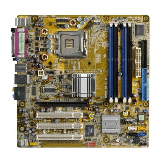
Motherboard layout 24.5cm (9.6in) PS/2KBMS CLPWD T: Mouse B: Keyboard Super LGA775 Bottom: Top: T:USB1 ATX12V 1394 B:USB2 USB2.0 Top: CPU_FAN T: USB3 SYS_FAN RJ-45 ® B: USB4 Intel 945P Top: Subwoofer Speaker Out Center Rear Speaker Out Top:Line In Below Center:Line Out Side Speaker Out... -
Page 6: Installing The Cpu
PnP cap/socket contacts/motherboard components. ASUS will shoulder the cost of repair only if the damage is shipment/transit-related. • Keep the cap after installing the motherboard. ASUS will process Return Merchandise Authorization (RMA) requests only if the motherboard comes with the cap on the LGA775 socket. - Page 7 Press the load lever with your thumb (A), then move it to the left (B) until it is released from the retention tab. R e t e n t i o n t a b R e t e n t i o n t a b R e t e n t i o n t a b R e t e n t i o n t a b R e t e n t i o n t a b...
- Page 8 Close the load plate (A), then push the load lever (B) until it snaps into the retention tab. The CPU fits in only one correct orientation. DO NOT force the CPU into the socket to prevent bending the connectors on the socket and damaging the CPU! Notes on Intel Notes on Intel...
-
Page 9: System Memory
240-pin footprint compared to the 184-pin DDR DIMM. DDR2 DIMMs are notched differently to prevent installation on a DDR DIMM socket. The following figure illustrates the location of the DDR2 DIMM sockets. P5LP-LE (Emery2-UL8E) 240-pin DDR2 DIMM sockets 3 . 1 3 . -
Page 10: Recommended Memory Configurations
Recommended memory configurations Recommended memory configurations Recommended memory configurations Recommended memory configurations Recommended memory configurations S o c k e t s S o c k e t s S o c k e t s S o c k e t s S o c k e t s M o d e M o d e... -
Page 11: Installing A Ddr2 Dimm
3 . 2 3 . 2 3 . 2 Installing a DDR2 DIMM Installing a DDR2 DIMM Installing a DDR2 DIMM 3 . 2 3 . 2 Installing a DDR2 DIMM Installing a DDR2 DIMM Unplug the power supply before adding or removing DIMMs or other system components. -
Page 12: Expansion Slots
Expansion slots In the future, you may need to install expansion cards. The following sub-sections describe the slots and the expansion cards that they support. Make sure to unplug the power cord before adding or removing expansion cards. Failure to do so may cause you physical injury and damage motherboard components. - Page 13 Standard interrupt assignments Standard interrupt assignments Standard interrupt assignments Standard interrupt assignments Standard interrupt assignments I R Q I R Q S t a n d a r d F u n c t i o n S t a n d a r d F u n c t i o n I R Q I R Q I R Q...
- Page 14 PCI Express slot PCI Express slot PCI Express slot PCI Express slot PCI Express slot This motherboard has one PCI Express Express slot, which supports a 164-pin x16 interface graphics card. PCI slots PCI slots PCI slots PCI slots PCI slots There are three 32-bit PCI slots on this motherboard.
-
Page 15: Jumpers
Removing the cap will cause system boot failure! CLRTC Clear CMOS Normal P5LP-LE (Emery2-UL8E) (Default) Clear RTC RAM 2 . 2 . C l e a r p a s s w o r d ( 3 - p i n C L P W D ) -
Page 16: Connectors
Connectors 6 . 1 6 . 1 6 . 1 6 . 1 6 . 1 Rear panel connectors Rear panel connectors Rear panel connectors Rear panel connectors Rear panel connectors 1 . 1 . P S / 2 m o u s e p o r t ( g r e e n ) . P S / 2 m o u s e p o r t ( g r e e n ) . - Page 17 Audio 2, 4, 6, or 8-channel configuration Audio 2, 4, 6, or 8-channel configuration Audio 2, 4, 6, or 8-channel configuration Audio 2, 4, 6, or 8-channel configuration Audio 2, 4, 6, or 8-channel configuration P o r t P o r t P o r t H e a d s e t / H e a d s e t /...
-
Page 18: Internal Connectors
NOTE: Orient the red markings on the floppy ribbon cable to PIN 1. P5LP-LE (Emery2-UL8E) Floppy disk drive connector A S U S P 5 L P - L E ( E m e r y 2 - U L 8 E ) - Page 19 (usually zigzag) on the IDE ribbon cable to PIN 1. PIN 1 P5LP-LE (Emery2-UL8E) IDE connector A S U S P 5 L P - L E ( E m e r y 2 - U L 8 E )
- Page 20 +12 Volts Ground +3 Volts P5LP-LE (Emery2-UL8E) ATX power connectors A S U S P 5 L P - L E ( E m e r y 2 - U L 8 E ) A S U S P 5 L P - L E ( E m e r y 2 - U L 8 E )
- Page 21 SATA4 SATA1 SATA3 P5LP-LE (Emery2-UL8E) SATA connectors I m p o r t a n t n o t e s o n S e r i a l A T A I m p o r t a n t n o t e s o n S e r i a l A T A...
- Page 22 F_1394 P5LP-LE (Emery2-UL8E) IEEE 1394 connector NEVER connect a U S B c a b l e U S B c a b l e U S B c a b l e U S B c a b l e to the IEEE 1394a connector.
- Page 23 These are not jumpers! DO NOT place jumper caps on the fan connectors. CPU_FAN SYS_FAN P5LP-LE (Emery2-UL8E) Fan connectors 8 . 8 . I n t e r n a l a u d i o c o n n e c t o r ( F _ L I N E _ I N )
-
Page 24: Front Panel Audioconnector
The S/PDIF module is purchased separately. SPDIF2 (White) SPDIF_OUT P5LP-LE (Emery2-UL8E) Digital audio connector 1 0 . 1 0 . 1 0 . 1 0 . -
Page 25: System Panel Connector
S y s t e m p a n e l c o n n e c t o r ( 1 0 - 1 p i n F _ P A N E L ) This connector supports several chassis-mounted functions. Reset HDD LED F_PANEL P5LP-LE (Emery2-UL8E) Power Button Power LED System panel connector S y s t e m p o w e r L E D S y s t e m p o w e r L E D •... - Page 26 A S U S P 5 L P - L E ( E m e r y 2 - U L 8 E ) A S U S P 5 L P - L E ( E m e r y 2 - U L 8 E ) A S U S P 5 L P - L E ( E m e r y 2 - U L 8 E ) A S U S P 5 L P - L E ( E m e r y 2 - U L 8 E ) A S U S P 5 L P - L E ( E m e r y 2 - U L 8 E )