
Related Manuals for Mitsubishi Electric PURY-80TMU


Summary of Contents for Mitsubishi Electric PURY-80TMU
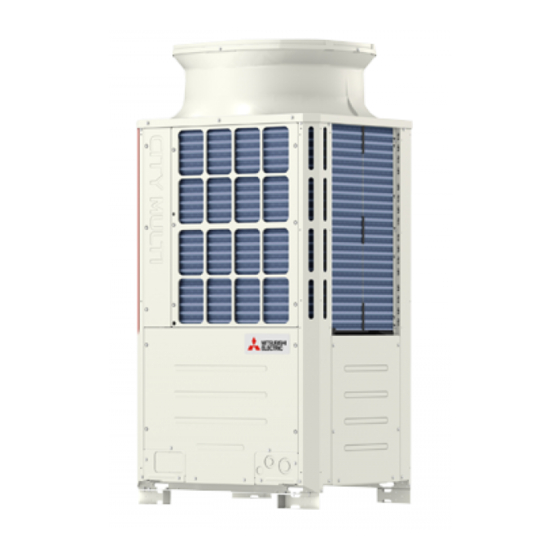
- Page 1 AIR CONDITIONERS CITY MULTI PURY-80TMU, 100TMU Models PURY-80TMU-A, 100TMU-A CMB-104, 105, 106, 108, 1010, 1013, 1016NU-F Service Handbook...
-
Page 2: Table Of Contents
Contents PRECAUTIONS FOR DEVICES .............. [1] Storage of Piping Material ..............3 [2] Brazing ....................4 [3] Airtightness Test ................5 [4] Vacuuming ..................5 COMPONENT OF EQUIPMENT ............. [1] Appearance of Components ............. 6 [2] Refrigerant Circuit Diagram and Thermal Sensor ......13 [3] Electrical Wiring Diagram .............. -
Page 3: Safety Precautions
• Do not reconstruct or change the settings of the protection devices. - If the pressure switch, thermal switch, or other protection device is shorted and operated forcibly, or parts other than those specified by Mitsubishi Electric are used, fire or explosion may result. –2–... -
Page 4: Precautions For Devices
1 1 1 1 1 PRECAUTIONS FOR DEVICES [1] Storage of Piping Material (1) Storage location Store the pipes to be used indoors. (Warehouse at site or owner’s warehouse) Storing them outdoors may cause dirt, waste, or water to infiltrate. (2) Pipe sealing before storage Both ends of the pipes should be sealed until immediately before brazing. -
Page 5: Brazing
[2] Brazing No changes from the conventional method, but special care is required so that foreign matter (ie. oxide scale, water, dirt, etc.) does not enter the refrigerant circuit. Example : Inner state of brazed section When non-oxide brazing was not used When non-oxide brazing was used Items to be strictly observed : 1. -
Page 6: Airtightness Test
[3] Airtightness Test Items to be strictly observed : 1. Pressurize the equipment with nitrogen up to the design pressure and then judge the equipment’s airtightness, taking temperature variations into account. Reasons : 1. Use of oxygen as the pressurized gas may cause an explosion. Vacuuming 1. -
Page 7: Component Of Equipment
2 2 2 2 2 COMPONENT OF EQUIPMENT [1] Appearance of Components In case of -A type. 4-way valve Fusible plug Accumulator SV block CV block Compressor –6–... - Page 8 Controller Box –7–...
- Page 9 MAIN board CNS1 CNS2 CN40 CN41 CNVCC3 Power Source for control 1-2 30V 1-3 30V 4-6 12V 5-6 5V CNVCC5 Power Source for control(5V) CN51 Indication distance 3-4 Compressor ON/OFF 3-5 Trouble CNRS3 Serial transmission to INV board CN3D CN3S Service LED CN20 CNAC3...
- Page 10 INV board CNDC2 1-3 DC-325V CN15V2 Power Output for IPM control CNVCC4 Power Output (5V) CNL2 Choke coil CNVCC2 Power Output 1-2 30V, 1-3 30V 4-6 12V, 5-6 5V CNDR2 Output to G/A board CNCT CNTH CNAC2 Power Input 5 L1 3 L3 CNFAN CN52C...
- Page 11 G/A board CNDC1 CN15V1 CNIPM1 CNDR1 Power board –10–...
- Page 12 BC controller CNTR CN12 CN02 Power M-NET supply transmission 1 EARTH CN03 –11–...
- Page 13 RELAY 10 board RELAY 4 board –12–...
-
Page 14: Refrigerant Circuit Diagram And Thermal Sensor
[2] Refrigerant Circuit Diagram and Thermal Sensor –13–... -
Page 15: Electrical Wiring Diagram
[3] Electrical Wiring Diagram –14–... - Page 16 2 CMB-104·105·106NU-F TB02 Shield wire ⎫ Transmission line ⎬ CONT.B ⎭ DC 30V CNTR CN02 CN03 CN26 CNP1 SV1B SV1A SV1C CN27 CNP3 SV2B SV2A SV2C CN13 CN28 SV3B TH11 SV3A SV3C TH12 CN10 CN29 SV4B SV4A SV4C CMB-105 106NU-F ONLY TH15 CN30 CN11...
- Page 17 –16–...
- Page 18 –17–...
-
Page 19: Standard Operation Data
[4] Standard Operation Data 1 Cooling Outdoor unit PURY-80TMU(-A) PURY-100TMU(-A) Items Indoor 26.7˚C(80˚F)/19.4˚C(67˚F) 26.7˚C(80˚F)/19.4˚C(67˚F) Ambient temp. DB/WB Outdoor 35˚C(95˚F) 35˚C(95˚F) Quantity Q’ty Indoor unit Quantity in operation Model – Main pipe 5(16.4) 5(16.4) Piping Branch pipe 5(16.4) 5(16.4) 5(16.4) 5(16.4) 5(16.4) 5(16.4) 5(16.4) 5(16.4) - Page 20 2 Heating Outdoor unit PURY-80TMU(-A) PURY-100TMU(-A) Items Indoor 21.1˚C(70˚F) 21.1˚C(70˚F) Ambient temp. DB/WB Outdoor 8.3˚C(47˚F)/6.1˚C(43˚F) 8.3˚C(47˚F)/6.1˚C(43˚F) Quantity Q’ty Quantity in operation Indoor unit Model – Main pipe 5(16.4) 5(16.4) Branch pipe Piping 5(16.4) 5(16.4) 5(16.4) 5(16.4) 5(16.4) 5(16.4) 5(16.4) 5(16.4)
-
Page 21: Function Of Dip Sw And Rotary Sw
[5] Function of Dip SW and Rotary SW (1) Outdoor unit Function according to switch operation Switch set timing Switch Function When off When on When off When on Unit address setting Set on 51~100 with the dial switch. Before power is turned on. For self diagnosis/ LED monitering display During normal operation when power... - Page 22 (2) Indoor unit DIP SW1, 3 Operation by SW Switch set timing Remarks Switch SW name Room temp. sensor position Indoor unit inlet Built in remote controller Clogged filter detect. None Provided Filter duration 100h 2500h OA intake Ineffective Effective Always ineffective for PKFY-NAMU Remote display select.
- Page 23 Setting of DIP SW4 Setting of DIP SW5 Model Circuit board used PDFY-10 ~ 32 PLFY-12 ~ 24 PLFY-32 ~ 48 Phase control PKFY-P-8 PKFY-P-12 – – – – Relay selection PDFY-40, 48 – –22–...
-
Page 24: Test Run
3 3 3 3 3 TEST RUN [1] Before Test Run (1) Check points before test run Neither refrigerant leak nor loose power source/ transmission lines should be found, if found correct immediately. Confirm that the resistance between the power source terminal block and the ground exceeds 2MΩ by measur- ing it with a DC500V megger. - Page 25 (3) Check points for test run when mounting options Result Built-in optional parts Content of test run Check point Mounting of drain Release connector of pump circuit, Local remote controller displays code water lifting-up check error detection by pouring No. “2503”, and the mechanism stops. mechanism water into drain pan water inlet.
- Page 26 (5) Check points for system structure Check points from installation work to test run. Classification Portion Check item Trouble Installation and Instruction for selecting combination of outdoor unit, piping and indoor unit followed? (Maximum number of indoor Not operate. units which can be connected, connecting model name, and total capacity.) Follow limitation of refrigerant piping length? For example, 70m (229ft) or less (total length : 220m (721ft)) at the farthest.
- Page 27 CENTRALLY CONTROLLED CENTRALLY CONTROLLED DRY COOL SENSOR DRY COOL SENSOR DAILY TIMER INSIDE DAILY TIMER INSIDE AUTO AUTO AUTO AUTO AUTO FAN AUTO FAN CLOCK CLOCK SPEED FILTER SPEED FILTER CHECK SET TEMP. REMAINDER CHECK HEAT HEAT SET TEMP. REMAINDER VENTILATION VENTILATION TEST RUN...
-
Page 28: Test Run Method
[2] Test Run Method Operation procedure Turn on universal power supply at least 12 hours before starting → Displaying “HO” on display panel for about two minutes button twice → Displaying “TEST RUN’’ on display panel Press TEST button → Make sure that air is blowing out Press MODE button to change from cooling to heating operation, and vice versa →... -
Page 29: Grouping Registration Of Indoor Units With Remote Controller
4 GROUPING REGISTRATION OF INDOOR UNITS WITH M-NET REMOTE CONTROLLER (1) Switch function • The switch operation to register with the remote controller is shown below: CENTRALLY CONTROLLED DRY COOL SENSOR DAILY TIMER INSIDE AUTO AUTO AUTO FAN CLOCK SPEED FILTER CHECK SET TEMP. - Page 30 (2) Attribute display of unit • At the group registration and the confirmation/deletion of registration/connection information, the type (attribute) of the unit is displayed with two English characters. Display Type (Attribute) of unit/controller Indoor unit connectable to remote controller Outdoor unit Local remote controller System controller (MJ) [Description of registration/deletion/retrieval]...
- Page 31 (3) Group registration of indoor unit Registration method • Group registration of indoor unit ................ 1 The indoor unit to be controlled by a remote controller is registered on the remote controller. [Registration procedure] 1 With the remote controller under stopping or at the display of “HO”, continuously press the button FILTER LOUVER...
- Page 32 Method of retrieval/confirmation • Retrieval/confirmation of group registration information on indoor unit ....2 The address of the indoor unit being registered on the remote controller is displayed. [Operation procedure] 1 With the remote controller under stopping or at the display of “HO”, continuously press the button FILTER LOUVER...
- Page 33 • Registered ßC (Alternative display) ßC SET TEMP. ON/OFF CLOCK ON OFF MODE TIMER FAN SPEED AIR DIRECTION FILTER LOUVER VENTILATION CHECK TEST PAR-F27MEA-US TIMER SET ßC 1 + 2 (Alternative display) 1 Set the address 2 Press the switch for confirmation (E) ßC ˚C...
- Page 34 Deletion of information on address not existing • Deletion of information on address not existing ........... 5 This operation is to be conducted when “6607” error (No ACK error) is displayed on the remote controller caused by the miss setting at test run, or due to the old memory remained at the alteration/modification of group composition, and the address not existing will be deleted.
-
Page 35: Control
5 5 5 5 5 CONTROL [1] Control of Outdoor Unit (1) Initial processing • When turning on power source, initial processing of microcomputer is given top priority. • During initial processing, control processing corresponding to operation signal is suspended. The control process- ing is resumed after initial processing is completed. - Page 36 (4) Frequency control • Depending on capacity required, capacity control change and frequency change are performed to keep constant evaporation temperature in cooling operations, and high pressure saturation temperature in heating operation. • Frequency change is performed at the rate of 2Hz/second across 20 ~ 105Hz range. Frequency control starting •...
- Page 37 (5) Oil return control (Electronic expansion valve <SLEV>) • Oil return LEV (SLEV) opening is dependent on compressor frequency and ambient temperature. • SLEV is closed (0) when compressor stops, and SLEV is set (64) for 10 minutes after starting compressor. (6) Defrost operation control Starting of defrost operations •...
-
Page 38: Control Of Bc Controller
[2] Control of BC Controller (1) Control of SVA, SVB and SVC SVA, SVB and SVC are turned on and off depending on connection mode. Mode Cooling Heating Stop Defrost Connection (2) Control of LEV LEV opening (sj) is controlled corresponding to operation mode as follows: (Number of pulse) Operation mode Cooling-only... -
Page 39: Operation Flow Chart
[3] Operation Flow Chart (1) Outdoor unit Start Normal operations Breaker turned on Trouble observed Stop “HO” blinks on the remote controller Note : 1 Set indoor ad- dress No. to remote controller Operation mode Cooling-only, Heating-only, Cooling/heating mixed 1. 52C Note : 2 2. - Page 40 (2) BC controller Start Normal operations Breaker turned on Trouble observed Stop Operation command 1. Operation mode judgement (cooling-only, heating-only, cooling/heating mixed) 2. Transmission to outdoor unit Receiving operation mode command from outdoor unit Note : 1 Error mode Error stop Cooling/heating mixed Operation mode Error code blinks on the...
- Page 41 (3) Indoor unit Start Normal operations Trouble observed Breaker turned on Stop Operation SW turned on Note :1 1. Protection function self-holding cancelled. 2. Indoor unit LEV fully closed. Note :2 Remove controller display extinguished Error mode Operation mode Error stop Error code blinks on Heating Cooling/heating...
- Page 42 (4) Cooling operation Cooling operation Normal operations 4-way valve OFF Test run Stop Indoor unit fan operations Test run start Thermostat ON 3-minute restart prevention 1. Inverter output 0Hz 1. Inverter frequency control 2. Indoor unit LEV, oil return LEV, 2.
- Page 43 (5) Heating operation Normal operations Heating operation Defrosting operations Note : 1 Stop Note : 2 Test run Defrosting operation 4-way valve OFF 4-way valve ON Test run start 1. Indoor unit fan stop 2. Inverter defrost frequency control 3. Indoor unit LEV fully opened, oil return LEV fully closed 4.
- Page 44 (6) Dry operation Dry operations Normal operations Thermostat ON 4-way valve OFF Stop Test run start Note : 2 Thermostat ON Inlet temp. 18˚C (64˚F) Note : 1 1. Indoor unit fan stop 1. Outdoor unit (Compressor) intermit- 2. Inverter output 0Hz tent operations 3.
-
Page 45: List Of Major Component Functions
[4] List of Major Component Functions Symbol Name Application Specification Check method (function) Compres- Adjust refrigerant circulation by controlling operating Low pressure shell scroll type frequency and capacity control valve with operating with capacity control mechanism pressure. Winding resistance: Each phase 0.388Ω (20˚C(68˚F)) Pressure High... - Page 46 Symbol Name Application Specification Check method (function) Thermistor THHS 1) Detects the inverter cooling fin temperature. =17kΩ 2) Provides inverter overheating protection. =4170 25/50 3) Controls the control box cooling fan. Rt = 17exp{4170( 273+50 273+t -20˚C (-4˚F) : 605.0kΩ -10˚C (14˚F) : 323.3kΩ...
- Page 47 Symbol Name Application Specification Check method (function) Pressure 1) Liquid pressure (high-pressure) detection sensor 2) LEV control Pressure 0~2.94MPa (0~426psi) Vout 0.5~3.5 V Con- Gnd (black) nector Vout (white) 1) Intermediate pressure detection Vc (DC5V) (red) 2) LEV control Thermistor TH11 LEV control (liquid refrigerant control) =15kΩ...
-
Page 48: Resistance Of Temperature Sensor
[5] Resistance of Temperature Sensor Thermistor for low temperature = 15kΩ ± 3% (TH3 ~ 9) = 7.465kΩ ± 2% (TH1, 10) Thermistor R Thermistor R = 15exp {3460 ( = 7.465exp {4057 ( 273+tc 273+120 273+tc 273+0 ∗˚F= × ˚C + 32 ∗˚F= ×... -
Page 49: Refrigerant Amount Adjustment
6 6 6 6 6 REFRIGERANT AMOUNT ADJUSTMENT Clarify relationship between the refrigerant amount and operating characteristics of CITY MULTI, and perform service activities such as decision and adjustment of refrigerant amount on the market. [1] Refrigerant Amount and Operating Characteristics The followings are refrigerant amount and operating characteristics which draw special attention. - Page 50 (2) Refrigerant Volume Adjustment Operation 1) Operating Characteristics Refrigerant Volume Characteristic items related to operating characteristics and the refrigerant volume are shown below. If the number of indoor units in operation increases during cooling, the required volume of refrigerant tends to increase (the amount of refrigerant in the accumulator tends to decrease), but the change is minimal.
- Page 51 At the time of shipping from the factory, the outdoor unit is charged with the amount of coolant shown in the follow- ing table, but since no extension piping is included, please carry out additional charging on-site. Outdoor Unit Model Name PURY-80TMU(-A) PURY-100TMU(-A) Refrigerant Charge Volume 10.0kg...
- Page 52 (3) Refrigerant Amount Adjustment Mode Operations 1 Procedure Depending on the operating conditions, it may be necessary either to charge with supplementary refrigerant, or to drain out some, but if such a case arises, please follow the procedure given below flow chart. Notes 1 As the refrigerant volume can not be adjusted in the heating mode, retrieve the refrigerant, evacu- ate air and then fill the specified volume of refrigerant if it is necessary to adjust the refrigerant...
- Page 53 Adjustment starts. Start cooling operation of all indoor units in a test run mode. Note 1 Note 1) As the refrigerant volume can not be adjusted in the heating mode, retrieve the refrigerant, evacuate air and then fill the specified volume of refrigerant if it is necessary to adjust the refrigerant Has the volume in the winter season.
- Page 54 1 Time required for recovering refrigerant from low pressure service port (minute) Low pressure MPa (psi) 0.34~0.44 0.44~0.54 0.54~0.74 Refrigerant amount (49.8~64) (64~78.2) (78.2~106.7) to be drawn out kg (oz) 1 (35.2) 2 (70.4) 3 (105.6) 12.0 10.5 10.0 4 (140.8) 16.0 14.0 13.0...
-
Page 55: Troubleshooting
7 7 7 7 7 TROUBLESHOOTING [1] Principal Parts Pressure Sensor (1) Judging Failure 1) Check for failure by comparing the sensing pressure according to the high pressure/low pressure pressure sensor and the pressure gauge pressure. Turn on switches 1, 3, 5, 6 (High) and 2, 4, 5, 6 (Low) of the digital display select switch (SW1) as shown below, and the sensor pressure of the high pressure/low pressure sensors is displayed digitally by the light emitting diode LD1. - Page 56 * Connector connection specifications on the pressure sensor body side. The connector’s pin numbers on the pressure sensor body side differ from the pin numbers on the main circuit board side. Sensor Body Side MAIN Board Side Pin1 Pin3 Vout Pin2 Pin2 Pin3...
- Page 57 (d) The refrigerant flow is as following figure. Hot gas (high pressured) flows in cooling mode and cool gas/liquid (low pressured) flows in heating mode. Please refer to the Refrigerant Circuit Diagram. And, ON/OFF of Solenoid valve is depends on the amount of running indoor units, ambient temperature and so on.
- Page 58 Judgment methods and likely failure mode Caution: The specifications of the outdoor unit (outdoor LEV) and indoor unit (indoor LEV) differ. For this reason, there are cases where the treatment contents differ, so follow the treatment specified for the appropriate LEV as indicated in the right column.
- Page 59 Outdoor LEV (SLEV) Coil Removal Procedure (configuration) As shown in the figure, the outdoor LEV is made in such a way that the coils and the body can be separated. Coils Stopper Lead Wires <Removing the Coils> Fasten the body tightly at the bottom (Part A in the figure) so that the body will not move, then pull out the coils toward the top.
- Page 60 Check Valves Block The refrigerant flow in the pipe 6, 7, 8 and 9 are depend on ON/OFF of the SV3, 4, 5 and 6. Please confirm by LED monitor display. You can open the cap of valve A, B and C, but 3 types of hexagon socket screw keys. The size is as follows. * Closed torque : A : 1.7kg·m (0.17N·m) [0.125lbFFt] B : 20kg·m (2.0N·m) [1.47lbFFt] C : 13kg·m (1.3N·m) [0.96lbFFt]...
- Page 61 Intelligent Power Module (IPM) Measure resistances between each terminal of IPM with tester, and use the results for troubleshooting. Specified resistance value is dependent on tester type to be used for resistance measurement, because diode inside IPM has non-linearity, thus difference of impedance and voltage in tester being influential. As the internal impedance of resistance range of analog tester equals to the center value of meter indication, the affect of internal impedance can be minimized if the tester having close center value of resistance range.
- Page 62 (2) Trouble and remedy of remote controller Symptom Cause Checking method & countermeasure Despite pressing of 1) M-NET transmission power source is not supplied a) Check transmission terminal block of remote controller from outdoor unit. remote controller for voltage. 1 Main power source of outdoor unit is not ON/OFF switch, i) In case of 17 ~ 30V →...
- Page 63 Symptom Cause “HO” display on re- (Without using MELANS) mote controller does 1) Outdoor unit address is set to “000.” not disappear and 2) Erroneous address. 1 Address setting of indoor unit to be coupled with remote controller Incorrect. ON/OFF switch is ineffective.
- Page 64 Symptom Cause Checking method & countermeasure “88” appears on re- [Generates at registration and confirmation] a) Confirm the address of unit to be mote controller at 1) Erroneous address of unit to be coupled. coupled. registration and 2) Disconnection of transmission line of unit to be b) Check the connection of transmission access remote coupled (No connection).
- Page 65 Transmission Power Circuit (30 V) Check Procedure If “ ” is not displayed by the remote control, investigate the points of the trouble by the following procedure and correct it. Check Item Judgment Response Disconnect the transmission line from TB3 DC24~30 V Check the transmission line for the following, and and check the TB3 voltage.
- Page 66 (3) Investigation of transmission wave shape/noise Control is performed by exchanging signals between outdoor unit, indoor unit and remote controller by M-NET transmission. If noise should enter into the transmission line, the normal transmission will be hindered causing erroneous operation. 1) Symptom caused by the noise entered into transmission line Cause Erroneous operation...
- Page 67 3) Checking and measures to be taken (a) Measures against noise Check the items below when noise can be confirmed on wave shape or the error code in the item 1) is generated. Items to be checked Measures to be taken 1 Wiring of transmission and power lines in Isolate transmission line from power line (5cm (2") or more).
- Page 68 4) Treatment of Inverter and Compressor Troubles If the compressor does not work when error codes 4240, 4250, 4340 or 4350 are detected, determine the point of malfunction by following the steps in the LED monitor display and countermeasures depending on the check code displayed, then perform the procedures below.
- Page 69 5) Troubleshooting at breaker tripping Check items Measures to be taken 1 Check the breaker capacity. The breaker’s capacity should be correct to “System design” in data book. 2 Check for a short circuit or grounding in the electrical Correct any defects. system other than the inverter.
- Page 70 Individual Parts Failure Judgment Methods. Part Name Judgment Method Diode Stack (DS) Refer to “Judging Diode Stack Failure.” Intelligent Power Module(IPM) Refer to “Judging IPM Failure.” Electromagnetic Contactor (52C) Measure the resistance value at each terminal. 44/42 34/32 Check Location Judgment Value 43/41 33/31 A1-A2 50~100kΩ...
- Page 71 Motor (Compressor) White Blue Blue Capacitor (C1) G/A board –70–...
- Page 72 (4) Troubleshooting the major components of the BC controller 1) Pressure sensor Pressure sensor troubleshooting flow START Note 1 Check pressure sensor, PS1, PS3, connectors for discon- nection, looseness, or incor- rect attachment. Take corrective action. Unit running? Note 2 Check on the LED monitor dis- play.
- Page 73 Note 1 : • Symptoms of incorrect i.e, reverse connection of PS and PS to BC controller board Symptom Cooling-only Cooling-principal Heating-only Heating-principal Insufficient SC11 large Warm indoor SC SC11 small Insufficient heating SC11 large cooling. SC16 small small. When SV SC16 small Warm indoor SC small SC16 small...
- Page 74 2) Temperature Sensor Thermistor troubleshooting flow Start Note 1 Disconnect applicable thermistor connector from the board. Note 2 Measure temperature of applicable thermistor (actual measured value). Note 3 Check thermistor resistance value. Compare temperature for thermistor resistance value with actual mea- sured valued.
- Page 75 Note 1 : • Board connector CN10 corresponds to TH11 through TH14, while connector CN11 corresponds to TH15 through TS15. Remove the applicable connector and check the sensor for each number. Note 2, 3 : 1. Pull the sensor connector from the I/O board. Do not pull on the lead wire. 2.
- Page 76 3) LEV, Solenoid Valve Troubleshooting Flow No cooling No heating Note 1 Check disconnection or looseness of connectors. Is there a problem? Correct the problem. Operate in cooling or heating (1 system only when there are plural systems) Heating operation Cooling or heating operation? Note 2...
- Page 77 1 LEV Note 1 : • Symptoms of incorrect connection to BC controller LEV board LEV No. Cooling-only Cooling-main Heating-only Heating-main ← ← ← Normal Insufficient cooling Insufficient cooling, insuf- Heating indoor SC small Insufficient cooling SH12 small, ficient heating PHM large Heating indoor SC small SC11 small...
- Page 78 (Self-diagnostic monitor) Measured Data Signal OUTDOOR MAIN board SW1 Setting 2 3 4 5 6 7 8 9 10 – LEV1 pulse 2 3 4 5 6 7 8 9 10 – LEV 3 pulse – BC controller bypass 2 3 4 5 6 7 8 9 10 SH12 output superheat BC controller...
- Page 79 2 Solenoid Valve Solenoid valve troubleshooting Operation OFF? Check solenoid valve wiring for incorrect connection, and connector disconnection or looseness. No problem. Correct the problem. Operate cooler and heater for the applicable solenoid valve’s refrigerant system only. Note 1 Clicking noise produced when working timing? Remove the coil and check for...
- Page 80 Solenoid valves (SVA, SVB, SVC) Coordination signals output from the board and solenoid valve operations. Note 1 : (SVA, SVB, SVC) SVA, SVB and SVC are turned on and off in accordance with operation mode. Mode Cooling Heating Stopped Defrosting Branch port Note 2 : (SVA, SVB, SVC) Measure temperature of piping on either side of SVA 1-A...
-
Page 81: Bc Controller Disassembly Procedure
[2] BC Controller Disassembly Procedure (1) Service panel Be careful on removing heavy parts. Procedure Photos & Illustrations 1. Remove the two screws securing the electric panel box, and then remove the box. 2. Remove the four screws securing the front panel and then remove the panel. - Page 82 (2) Control Box Be careful on removing heavy parts. Procedure Photos <CMB-P104, 105, 106NU-F> 1. Removing the single screw that secures the elec- tric panel box cover provides access to the box con- tents for checking. 1 Check electrical lead wires and transmission lead terminal connections.
- Page 83 (3) Thermistor (Liquid and gas piping temperature detection) Be careful when removing heavy parts. Procedure Photos 1. Remove the service panel 1 Use the procedure under (1)-1.2 to check TH11, TH12, and TH15. 2. Disconnect the piping sensor lead from the control- ler panel.
- Page 84 (5) LEV Be careful on removing heavy parts. Procedure Photos 1. Remove the service panel. See (1)-1.2.3.4. 2. Replace the applicable LEV. Important! 1 When performing the above procedure, be sure to allow for enough service space in the ceiling area LEV3 for welding.
- Page 85 Check Code List Check Code Check Content 0403 Serial transmission abnormality 0900 Trial operation 1102 Discharge temperature abnormality 1111 Low pressure saturation temperature sensor abnormality (TH2) 1301 Low pressure abnormality (OC) 1302 High pressure abnormality (OC) 1368 Liquid side pressure abnormality (BC) 1370 Intermediate pressure abnormality (BC) 1500...
- Page 86 Check Code Check Content 6606 Communications with transmission processor abnormality 6607 No ACK abnormality 6608 No response abnormality 6831 MA Not receiving communications abnormality 6834 MA Communications starting abnormality 6832 MA Communications Synchronous recovery Abnormality 6833 MA Communications Transmit/ receive Hardware Abnormality 7100 Total capacity abnormality 7101...
-
Page 87: Self-Diagnosis And Countermeasures Depending On The Check Code Displayed
[3] Self-diagnosis and Countermeasures Depending on the Check Code Displayed (1) Mechanical Checking code Meaning, detecting method Cause Checking method & Countermeasure 0403 Serial If serial transmission cannot be 1) Wiring is defective. Check 1, the connections, 2, contact transmission established between the MAIN and at the connectors and 3, for broken abnormality... - Page 88 Checking code Meaning, detecting method Cause Checking method & Countermeasure 1102 Discharge 1. When 140˚C (284˚F) or more 1) Gas leak, gas shortage. See Refrigerant amount check. temperature discharge temperature is de- abnormality tected during operations (the 2) Overload operations. Check operating conditions and opera- (Outdoor unit) first time), outdoor unit stops...
- Page 89 Checking code Meaning, detecting method Cause Checking method & Countermeasure 1301 Low pressure When starting from the stop mode 1) Internal pressure is dropping due Refer to the item on judging low pres- abnoramlity for the first time, (if at the start of bind to a gas leak.
- Page 90 Checking code Meaning, detecting method Cause Checking method & Countermeasure 1302 High pressure When press. sensor detects 1) Fall in internal press. caused by See Trouble check of pressure sen- abnoramlity 2 0.098MPa (14.22psi) or less just gas leak. sor. (Outdoor unit) before starting of operation, erro 2) Press.
- Page 91 Checking code Meaning, detecting method Cause Checking method 1500 Overcharged 1. When discharge superheart 1) Excessive refrigerant charge. Check refrigerant amount. refrigerant 10 (18) deg is keeping for 10 abnormality minutes or discharge superheat 2) Thermistor trouble (TH1). Check resistance of thermistor. 20 (36) deg for 15 minutes, outdoor unit stops once, and af- 3) Pressure sensor trouble (63HS).
- Page 92 Checking code Meaning, detecting method Cause Checking method & Countermeasure 1505 Suction 1. Judging that the state when the • Operation while neglecting to open Once vacuum operation protection is pressure suction pressure reaches 0MPa ball valve. Especially for the ball commenced, do not attempt to abnormality during compressor operation...
- Page 93 Checking code Meaning, detecting method Cause Checking method & Countermeasure 4103 Reverse phase Reverse phase (or open phase) in 1) The phases of the power supply (L1, If there is reverse phase before the abnormality the power system is being de- L2, L3) have been reversed.
- Page 94 Checking code Meaning, detecting method Cause Checking method & Countermeasure 4116 Fan speed (Detects only for PKFY-NAMU-A/ 1) Disconnection of or slipping off of • Confirm slipping off of connector abnormality NGMU-A/NFMU-A) fan speed detecting connector (CN33) on indoor controller (motor 1.
- Page 95 Checking code Cause Checking method & Countermeasure Meaning, detecting method 1 If VDC 4220 220 V is de- 1) The power supply voltage • Check if an instantaneous stop or power failure, etc. voltage tected during inverter is abnormal. has occurred. abnormality operation.
- Page 96 Checking code Meaning, detecting method Cause Checking method & Countermeasure 4240 Over load If IDC 103 A is detected continu- 1) Air passage short cycle. Is the unit’s exhaust short cycling? protection ously for 10 minutes during opera- tion of the inverter after 5 or more 2) The heat exchanger is clogged.
- Page 97 Checking code Meaning, detecting method Cause Checking method & Countermeasure 4260 Cooling fan If the heat sink temperature (THHS) 1) Same as “4230.” Same as “4230.” abnormality 100°C (212°F) for 20 minutes or longer just before the inverter starts. 5101 Discharge <Other than THHS>...
- Page 98 Checking code Meaning, detecting method Cause Checking method & Countermeasure 1 When pressue sensor detects 5201 Pressure 1) Pressutre sensor trouble. See Troubleshooting of pressure sensor 0.098MPa (14.22psi) or less dur- sensor. abnormality ing operation, outdoor unit once (outdoor unit) stops with 3 minutes restarting 2) Inner pressure drop due to a leak- mode, and restarts if the detected...
- Page 99 (2) Communication/system Checking Meaning, detecting method Cause Checking method & Countermeasure code 1) Two or more controllers of outdoor At the genration of 6600 error, release the error by 6600 Multiple address error unit, indoor unit, remote controller, remote controller (with stop key) and start again. BC controller, etc.
- Page 100 Checking Meaning, detecting method Cause Checking method & Countermeasure code 6602 Transmission processor hardware Checking method and processing error Transmission line Shut off the power source of outdoor/in- installed while turning door units/BC controller and make it again. power source on? Check power source of indoor unit.
- Page 101 Checking Meaning, detecting method Cause Checking method & Countermeasure code 6606 Communications with transmis- 1) Data is not properly transmitted due Turn off power sources of indoor unit, BC controller sion processor error to casual errouneous operation of and outdoor unit. the generating controller.
- Page 102 Checking Meaning, detecting method code 6607 No ACK error When no ACK signal is detected in 6 continuous times with 30 second interval by transmission side controller, the transmission side detects error. Note: The address/attribute shown on remote controller indicates the controller not providing the answer (ACK).
- Page 103 Checking Meaning, detecting method code 6607 No ACK error When no ACK signal is detected in 6 continuous times with 30 second (continued) interval by transmission side controller, the transmission side detects error. Note: The address/attribute shown on remote controller indicates the controller not providing the answer (ACK).
- Page 104 Checking Meaning, detecting method code 6607 No ACK error When no ACK signal is detected in 6 continuous times with 30 second (continued) interval by transmission side controller, the transmission side detects error. Note: The address/attribute shown on remote controller indicates the controller not providing the answer (ACK).
- Page 105 Checking Meaning, detecting method code 6607 No ACK error When no ACK signal is detected in 6 continuous times with 30 second (continued) interval by transmission side controller, the transmission side detects error. Note: The address/attribute shown on remote controller indicates the controller not providing the answer (ACK).
- Page 106 Checking code Meaning, detecting method Cause Checking method & Countermeasure 6608 No response error 1) At the collision of mutual transmis- a) Generation at test run. sion data when transmission wiring Turn off the power sources of outdoor Though acknowledgement of re- is modified or the polarity is unit (OC), indoor unit (IC) and Fresh ceipt (ACK) is received after...
- Page 107 (3) System error Checking Meaning, detecting method Cause Checking method & Countermeasure code 7100 Total capacity error 1) Total capacity of indoor units in the a) Check for the model total (capacity cord total) of same refrigerant system exceeds indoor units connected. Total capacity of indoor units in the following: b) Check whether indoor unit capacity code (SW2)
- Page 108 Checking Meaning, detecting method Cause Checking method & Countermeasure code 7102 Connected unit count over 2) The Outdoor unit address is being a) Check for the model total (capacity code total) set to 51~100 under automatic ad- of indoor units connected. dress mode (Remote controller dis- plays “HO”).
-
Page 109: Led Monitor Display
[4] LED Monitor Display (1) How to read LED for service monitor By setting of DIP SW1-1 ~ 1-8, the unit operating condition can be observed with the service LED on the control circuit board. (For the relation of each DIP SW to the content, see the table provided.) As shown in the figure below, the LED consist of 7 segments is put in 4 sets side by side for numerical and graphic display. - Page 110 E: E2 Contents stored in the E2PROM; M: Monitored by the IC through communications; E*: Stored in service memory. Item Display Remarks 12345678910 0000000000 Relay Output COMP Crankcase 21S4 Lights for LD8 is a relay output indicator which Display 1 (Lights Operat- Heater ON Normal...
- Page 111 Item Display Remarks 12345678910 1010100000 Outdoor Unit High Discharge Overcur- Heat Sink Overcur- Over- Lights up if an error Preliminary Error Pressure Pressure Tempera- rent Thermostat rent charged delay has occurred History Error 1, 2 Error ture Error Protection Operation Break Refrigerant between the time the...
- Page 112 Item Display Remarks 12345678910 0010110000 THHS Data -99.9 ~ 999.9 ↑ 1010110000 HPS Data ↑ 0110110000 TH7 Data 1110110000 – – 0001110000 – – 1001110000 – – 0101110000 LPS Data -99.9 ~ 999.9 1101110000 – – 0011110000 – – 1011110000 Accumulator Level Accumulator Level: 0~9 (“AL=”...
- Page 113 When there is an error stop with No95-121,the data on error stops or the data immediately before the error postpone- ment stop, which is stored in service memory, are displayed. Item Display Remarks 12345678910 1100101000 IC7 Address/ 0 ~ 99 0 ~ 99 Capacity Code ↑...
- Page 114 When there is an error stop with No95-121,the data on error stops or the data immediately before the error postpone- ment stop, which is stored in service memory, are displayed. Item Display Remarks 12345678910 0000111000 – – 1000111000 -99.9 ~ 999.9 ↑...
- Page 115 Item Display Remarks 12345678910 0011000100 BC LEV 1 Data -99.9 ~ 999.9 ↑ 1011000100 BC LEV 3 Data 0111000100 – – 1111000100 – – 0000100100 IC1 liquid Pipe -99.9 ~ 999.9 Temperature 1000100100 IC2 liquid Pipe ↑ Temperature 0100100100 IC3 liquid Pipe ↑...
- Page 116 Item Display Remarks 12345678910 0110010100 IC7 Gas Pipe -99.9 ~ 999.9 Temperature ↑ 1110010100 IC8 Gas Pipe Temperature ↑ 0001010100 IC9 Gas Pipe Temperature ↑ 1001010100 IC10 Gas Pipe Temperature ↑ 0101010100 IC11 Gas Pipe Temperature ↑ 1101010100 IC12 Gas Pipe Temperature ↑...
- Page 117 Item Display Remarks 12345678910 0001001100 IC9 SC -99.9 ~ 999.9 ↑ 1001001100 IC10 SC ↑ 0101001100 IC11 SC ↑ 1101001100 IC12 SC ↑ 0011001100 IC13 SC ↑ 1011001100 IC14 SC ↑ 0111001100 IC15 SC ↑ 1111001100 IC16 SC 0000101100 IC1 LEV Opening 0 ~ 9999 pulse ↑...
- Page 118 Item Display Remarks 12345678910 10100111000 IC6 Operation Mode/ Branch Number On the left 0110011100 IC7 Operation Mode/ (LD1~LD4), the IC Branch Number address, and on the right (LD5~LD8), the 11100111000 IC8 Operation Mode/ capacity code is Branch Number displayed (displayed alternately every 5 0001011100 IC9 Operation Mode/...
-
Page 119: Preparation, Repairs And Refrigerant Refilling When Repairing Leaks
8 PREPARATION, REPAIRS AND REFRIGERANT REFILLING WHEN REPAIRING LEAKS [1] Location of leaks: Extension piping or indoor units (when cooling) (Pump down operation) 1 Attach a pressure gage to the low-pressure servicing check joint (CJ2). 2 Stop all of the indoor units. When the compressor has stopped, shut off the liquid ball valve (BV2) for the outdoor unit. -
Page 120: Location Of Leaks: Extension Piping Or Indoor Units (Heating Mode)
[3] Location of leaks: Extension piping or indoor units (Heating mode) 1 Test run all indoor units in heating mode. 1. With SW3-1 on the MAIN board of the outdoor unit set to ON and SW3-2 OFF → ON to test run all indoor units. - Page 121 Service Handbook PURY-80TMU, 100TMU PURY-80TMU-A, 100TMU-A CMB-104, 105, 106, 108, 1010, 1013, 1016NU-F HEAD OFFICE: TOKYO BLDG., 2-7-3, MARUNOUCHI, CHIYODA-KU, TOKYO 100-8310, JAPAN Issued in Dec. 2005 HWE05220 New publication effective Dec. 2005 Printed in Japan Specifications subject to change without notice.