Table of Contents
Advertisement
Quick Links
Operation Manual
CLI Screens
Thank you for purchasing our product.
This manual provides important information about safe and proper operations of this Switching
Hub.
Please read the "Important Safety Warnings" on pages 3 to 4.
Any problems or damage resulting from disassembly of this Switching Hub by customers
are note covered by the warranty.
Applicable product names and model numbers are described on page 2.
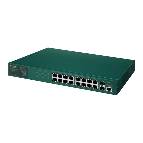
Layer 2 Switching Hub
Model Number: PN28160A/PN28240A
Advertisement
Table of Contents

Related Manuals for Panasonic PN28160A


Summary of Contents for Panasonic PN28160A
- Page 1 Layer 2 Switching Hub Operation Manual CLI Screens Model Number: PN28160A/PN28240A Thank you for purchasing our product. This manual provides important information about safe and proper operations of this Switching Hub. Please read the "Important Safety Warnings" on pages 3 to 4.
- Page 2 This operation manual is applicable to the following Switching Hubs: Product name Model No. Firmware version Switch-M24eG PN28240A 1.0.0.105 or higher Switch-M16eG PN28160A 1.0.0.105 or higher...
-
Page 3: Important Safety Instructions
Important Safety Instructions This chapter contains important safety instructions for preventing bodily injury and/or property damage. You are required to follow them. Severity of bodily injury and/or property damage, which could result from incorrect use of the Switching Hub, are explained below. WARNING This symbol indicates a potential hazard that could result in serious injury or death. - Page 4 WARNING Do not install this Switching Hub at the location with continuous vibration or strong shock, or at the unstable location. Deviation could lead to injury and/or equipment failure. Do not install any module other than the separately sold SFP module to SFP extension slot.
-
Page 5: Basic Instructions For The Use Of This Product
Basic Instructions for the Use of This Product For inspection and/or repair, consult the shop. Use commercial power supply from a wall socket, which is close and easily accessible to this Switching Hub. Unplug the power cord when installing or moving this Switching Hub. ... - Page 6 Panasonic will not be liable for any damage resulting from the operation not in accordance with this document or the loss of communications, which may or may not be caused by failure and/or malfunction of this product. The contents described in this document may be changed without prior notice.
-
Page 7: Table Of Contents
Table of Contents Important Safety Instructions ..................3 Basic Instructions for the Use of This Product .............. 5 1. Command Hierarchy ..................9 2. Basic Information Display ..................13 3. Basic Switch Configuration ................19 3.1. System Administration Configuration ..............19 3.1.1. Username and Password Configuration ............26 3.2. - Page 8 11. Save and Display of Configuration Information ............258 12. Obtaining Technical Support Information ............263 Appendix A. Specifications ..................266 Appendix B. Procedures for Console Port Connection using Windows HyperTerminal...267 Appendix C. Easy IP Address Setup Function ............268 Appendix D. Example of Network Configuration using Loop Detection Function and Its Precautions ....................269 Appendix E.
-
Page 9: Command Hierarchy
1. Command Hierarchy There are four levels in the hierarchy. (1) User mode: This is the default mode after login. Limited operations are allowed. (2) Privileged mode: This mode allows you to check the state of the Switching Hub, to edit configuration files, etc. - Page 10 configure Command • Enter this command to switch from the Privileged mode to the Global configuration mode. M24eG# ····································· Privileged mode M24eG# configure ························· Privileged mode Global configuration mode M24eG(config)# ··························· Global configuration mode interface Command • Enter this command to switch from the Global configuration mode to the Interface configuration mode.
- Page 11 end Command • Enter this command to switch from configuration modes to the Privileged mode. M24eG(config-if)# end ················· Interface configuration mode Privileged mode M24eG# configure M24eG(config)# end ··················· Global configuration mode Privileged mode logout Command • Enter this command to return to the menu screen from any command mode. M24eG(config)# logout ·················...
- Page 12 Command-line Completion Support • Enter a question mark (?) immediately after a command. This will show command candidates to complete the entered command. M24eG# configure M24eG(config)# ip address A.B.C.D - IP address (e.g. 10.0.0.1) M24eG(config)# ip address Fig. 1-3 Command-line completion support Abbreviated Command Entry After entering just enough characters of a command or an argument to identify it uniquely, you can omit the rest of the command or the argument.
-
Page 13: Basic Information Display
2. Basic Information Display Enter the commands listed below in the "Privileged mode" to show this Switching Hub's basic information. Command to show the system information (up time and version information) M24eG# show sys-info Command to show the address information (MAC address and IP address information) M24eG# show ip conf... - Page 14 <Command Entry Example> An example of executing the command to show the system information is shown below. M24eG> enable M24eG# show sys-info System up for : 0 days, 00:00:00 Boot Code Version : 00.00.xx Runtime Code version : 1.0.0.xx Hardware Information Version : Version1 DRAM Size...
- Page 15 (6) DRAM Size Shows the Switching Hub's DRAM memory size. (7) Fixed Baud Rate Shows the baud rate of the Switching Hub's console port. (8) Flash Size Shows the Switching Hub's flash memory size. (9) Administration Information Shows the Switching Hub's administration information. (10) Switch Name Shows the Switching Hub's current host name.
- Page 16 <Command Entry Example> An example of executing the command to show the address information is shown below. M24eG> enable M24eG# show ip conf MAC Address : xx:xx:xx:xx:xx:xx IP Address : 0.0.0.0 Subnet Mask : 0.0.0.0 Default Gateway : 0.0.0.0 M24eG# Fig.
- Page 17 show sys-info Shows the Switching Hub's system information (such as up time and version information). [Parameter] Parameter name Description None None [Factory Default Setting] Parameter name Factory default setting None None [Setting Range] Parameter name Setting range None None [Note] Parameter name Note None...
- Page 18 show ip conf Shows the address information (such as MAC address and IP address) of the Switching Hub. [Parameter] Parameter name Description None None [Factory Default Setting] Parameter name Factory default setting None None [Setting Range] Parameter name Setting range None None [Note]...
-
Page 19: Basic Switch Configuration
3. Basic Switch Configuration 3.1. System Administration Configuration Configure the host name, installation location and contact information in "Global configuration mode." Confirm the configuration information by executing the "show sys-info" command in "Privileged mode." Command to show the system information M24eG# show sys-info Command to set the host name... - Page 20 <Command Entry Example> An example of executing the command to show the system information is shown below. M24eG> enable M24eG# show sys-info System up for : 0 days, 00:00:00 Boot Code Version : xx.xx.xx Runtime Code version : x.x.x.xx Hardware Information Version : Version1 DRAM Size...
- Page 21 show sys-info Shows the system information. [Parameter] Parameter name Description None None [Factory Default Setting] Parameter name Factory default setting None None [Setting Range] Parameter name Setting range None None [Note] Parameter name Note None None...
- Page 22 hostname <hostname> Sets or edits the system name. no hostname Deletes the system name. [Parameter] Parameter name Description <hostname> Set the system name. [Factory Default Setting] Parameter name Factory default setting <hostname> None [Setting Range] Parameter name Setting range <hostname> Up to 50 one-byte characters Allowed characters: alphanumeric character (A-Z, a-z,...
- Page 23 snmp-server location <server location> Sets or edits the installation location information. no snmp-server location Deletes the installation location information. [Parameter] Parameter name Description <server location> Set the installation location. [Factory Default Setting] Parameter name Factory default setting <server location> None [Setting Range] Parameter name Setting range...
- Page 24 snmp-server contact <server contact> Sets or edits the contact information. no snmp-server contact Deletes the contact information. [Parameter] Parameter name Description <server contact> Set the contact information. [Factory Default Setting] Parameter name Factory default setting <server contact> None [Setting Range] Parameter name Setting range <server contact>...
- Page 25 <Configuration Example> Overview: Set this Switching Hub's administration information (host name, installation location, and contact information). (1) Set this Switching Hub's name to "Switch." (2) Set this Switching Hub's installation location to "Office-2F." (3) Set this Switching Hub's contact information to "manager." M24eG>...
-
Page 26: Username And Password Configuration
3.1.1. Username and Password Configuration Configure the username and password for this Switching Hub in "Global configuration mode." Command to set the username and password M24eG(config)# username <new username>... - Page 27 username <new username> Sets or edits the username and password. * Upon entering this command, you are required to enter your old password once and your new password twice to set the new password. [Parameter] Parameter name Description <new username> Enter a new username.
- Page 28 <Configuration Example> Overview: Set a username and password for the Switching Hub. (1) Set a new username to "user1." (2) Enter the current password. (The factory default setting is "manager.") (3) Enter a new password. (4) Enter the new password again. M24eG>...
-
Page 29: Ip Address Configuration
3.2. IP Address Configuration Configure the IP address settings of this Switching Hub in "Interface configuration mode." Confirm the configuration information by executing the "show ip conf" command in "Privileged mode." Command to show the IP address M24eG# show ip conf Command to set the IP address M24eG(config)# ip address <ip-address>... - Page 30 <Command Entry Example> An example of executing the command to show the address information is shown below. M24eG> enable M24eG# show ip conf MAC Address : xx:xx:xx:xx:xx:xx IP Address : 0.0.0.0 Subnet Mask : 0.0.0.0 Default Gateway : 0.0.0.0 M24eG# Fig.
- Page 31 ip address <ip-address> <mask> [<default-gateway>] Sets or edits the IP address, subnet mask and/or default gateway. no ip address Deletes the IP address, subnet mask and/or default gateway. [Parameter] Parameter name Description <ip-address> Enter an IP address to be set or edited. <mask>...
- Page 32 <Configuration Example> (1) Set the Switching Hub's IP address to "192.168.1.1," subnet mask to "255.255.255.0" and default gateway to "192.168.1.254." M24eG> enable M24eG# configure M24eG(config)# ip address 192.168.1.1 255.255.255.0 192.168.1.254 Interface vlan1 my HWaddr: xx:xx:xx:xx:xx:xx my IPaddr: 192.168.1.1 Options: subnet mask: 255.255.255.0 IP broadcast: 192.168.1.255 gateway: 192.168.1.254 M24eG(config)#...
-
Page 33: Snmp Configuration
3.3. SNMP Configuration Configure the SNMP agent setting in "Global configuration mode." Confirm the configuration information by executing the "show snmp" command in "Privileged mode." Command to show the SNMP information M24eG# show snmp Command to enable the SNMP agent M24eG(config)# snmp-server agent Command to disable the SNMP agent... - Page 34 <Command Entry Example> An example of executing the command to show the SNMP information is shown below. M24eG> enable M24eG# show snmp SNMP Agent: Disabled SNMP Manager List: Status IP Address Access SNMP Community String ---- -------- --------------- ------ -------------------------------- Enabled 0.0.0.0 public...
- Page 35 (2) SNMP Manager List Lists the administrative information about SNMP manager. (3) No. Shows the entry number assigned to the SNMP manager. (4) Status Shows the status of the SNMP manager. Enabled Access by the SNMP manager for the entry number is enabled. Disabled Access by the SNMP manager for the entry number is disabled.
- Page 36 (12) Version Shows the SNMP trap type. SNMP v1 traps are sent. SNMP v2 traps are sent. (13) Trap Community String Shows the current community name, used for sending SNMP traps. (14) Individual Trap Shows the setting of SNMP trap events. (15) SNMP Authentication Failure Shows the status of SNMP authentication failure trap.
- Page 37 show snmp Shows the SNMP configuration information. [Parameter] Parameter name Description None None [Factory Default Setting] Parameter name Factory default setting None None [Setting Range] Parameter name Setting range None None [Note] Parameter name Note None None...
- Page 38 snmp-server agent Enables the SNMP agent. no snmp-server agent Disables the SNMP agent. [Parameter] Parameter name Description None None [Factory Default Setting] Parameter name Factory default setting None no snmp-server agent The SNMP agent is disabled. [Setting Range] Parameter name Setting range None None...
- Page 39 snmp-server community <id> <community> <ro / rw> <ip-address> Sets or edits the SNMP manager administrative information. no snmp-server community <id> Deletes the SNMP manager administrative information. [Parameter] Parameter name Description <id> Set the entry number of the SNMP manager. <community> Set the community name for the SNMP manager.
- Page 40 snmp-server host <id> type <v1/v2> <ip-address> trap <community> Sets or edits the SNMP trap receiver settings. no snmp-server host <id> Deletes the SNMP trap receiver settings. [Parameter] Parameter name Description <id> Set the entry number of the SNMP trap receiver. <v1/v2>...
- Page 41 snmp-server enable traps snmp authentication Enables the trap sending settings for an SNMP authentication failure. no snmp-server enable traps snmp authentication Disables the trap sending settings for an SNMP authentication failure. [Parameter] Parameter name Description None None [Factory Default Setting] Parameter name Factory default setting None...
- Page 42 snmp-server enable traps linkupdown <port> Adds a port to which the trap is sent when the link status changes. no snmp-server enable traps linkupdown <port> Deletes a port to which the trap is sent when the link status changes. [Parameter] Parameter name Description <port>...
- Page 43 <Configuration Example> Overview: Enable the SNMP function, then set the community name and the address information. (1) Enable the SNMP agent. (2) Set the SNMP manager administrative information as below. community 1, private, Read-Write, 192.168.1.200 (3) Set the SNMP manager administrative information as below. community 2, public, Read-Only, 192.168.1.200 (4) Set the SNMP trap receiver settings as below.
-
Page 44: Port Configuration
3.4. Port Configuration Configure the port setting in "Interface configuration mode." Confirm the configuration information by executing the "show interface info" command in "Privileged mode." Command to show the port information M24eG# show interface info Command to show the detailed port information M24eG# show interface [gi0/1-gi0/24] Command to enable the port status... - Page 45 <Command Entry Example> An example of executing the command to show the port information is shown below. M24eG> enable M24eG# show interface info Interface Name Status Mode FlowCtrl Auto-MDI Jumbo --------- ---------------- -------- -------- -------- -------- -------- gi0/1 Port_1 Disabled Auto Disabled Disabled Disabled gi0/2 Port_2...
- Page 46 (4) Mode Shows the port communication speed and duplex mode (full or half). Auto The auto negotiation function is enabled when the port link is down. While the link is up, the string enclosed in parentheses shows the communication speed and full-duplex/half-duplex mode. 1000F The port is in the 1000 Mbps full-duplex mode.
- Page 47 <Command Entry Example> An example of executing the command to show the detailed port information is shown below. M24eG> enable M24eG# show interface gi0/1 Interface GigabitEthernet0/1 (12) Admin Status : Enabled Link Status : Up (13) Auto Negotiate : Enabled Duplex : Full (14)
- Page 48 (6) MDIX Mode Shows the Auto MDI/MDI-X setting. Auto The Auto MDI/MDI-X is enabled. Crossover The Auto MDI/MDI-X is disabled. (7) Line Protocol Shows the loop detection function setting. The loop detection is enabled. Disabled The loop detection is disabled. (8) Line Shut-down Shows the time between the loop-detection/port-shutdown and the auto-recovery.
- Page 49 (13) Duplex Shows the duplex mode. Full Full-duplex mode. Half Half-duplex mode. Auto Waiting for a link up under the auto negotiation mode. (14) Speed Shows the port's communication speed mode. Auto Waiting for a link up under the auto negotiation mode. 1000Mbps The port is linked up at 1000 Mbps.
- Page 50 show interface info Shows the interface setting information. [Parameter] Parameter name Description None None [Factory Default Setting] Parameter name Factory default setting None None [Setting Range] Parameter name Setting range None None [Note] Parameter name Note None None...
- Page 51 show interface <IFNAME> Shows the interface name. [Parameter] Parameter name Description <IFNAME> Set the interface name. [Factory Default Setting] Parameter name Factory default setting <IFNAME> None [Setting Range] Parameter name Setting range <IFNAME> <Switch-M24eG> GigabitEthernet0/1 to GigabitEthernet0/24 <Switch-M16eG> GigabitEthernet0/1 to GigabitEthernet0/16 The name can be abbreviated.
- Page 52 shutdown Shuts down a port. no shutdown Releases a port. [Parameter] Parameter name Description None None [Factory Default Setting] Parameter name Factory default setting None no shutdown [Setting Range] Parameter name Setting range None None [Note] Parameter name Note None None...
- Page 53 speed-duplex < auto | {10|100}-half | {10|100}-full > Sets the port mode. [Parameter] Parameter name Description < auto | Set the port mode. {10|100}-half | auto Set the mode to "auto negotiation." {10|100}-full > 10-half Set the mode to "10 Mbps half-duplex." 10-full Set the mode to "10 Mbps full-duplex."...
- Page 54 flow-control Enables the flow control function. no flow-control Disables the flow control function. [Parameter] Parameter name Description None None [Factory Default Setting] Parameter name Factory default setting None no frow-control The flow control function is disabled. [Setting Range] Parameter name Setting range None None...
- Page 55 name <string> Sets the port name. [Parameter] Parameter name Description < string > Set the port name. [Factory Default Setting] Parameter name Factory default setting < string > Nothing is set. [Setting Range] Parameter name Setting range < string > Up to 15 one-byte characters Allowed characters: alphanumeric character (A-Z, a-z,...
- Page 56 mdix auto Enables the Auto MDI/MDI-X function. no mdix auto Disables the Auto MDI/MDI-X function. [Parameter] Parameter name Description None None [Factory Default Setting] Parameter name Factory default setting None <Switch-M24eG> Ports 1 to 22: no mdix auto The Auto MDI/MDI-X function is disabled. Ports 23 to 24: mdix auto The Auto MDI/MDI-X function is enabled.
- Page 57 [Setting Range] Parameter name Setting range None None [Note] Parameter name Note None None...
- Page 58 jumbo Enables jumbo frames. no jumbo Disables jumbo frames. [Parameter] Parameter name Description None None [Factory Default Setting] Parameter name Factory default setting None no jumbo Jumbo frame is disabled. [Setting Range] Parameter name Setting range None None [Note] Parameter name Note None When jumbo frame is enabled, the maximum frame size is...
- Page 59 <Configuration Example 1> Overview: Set the status of Port 1 to be closed. (1) Move to the interface configuration mode for Port 1. (2) Shut down Port 1. M24eG> enable M24eG# configure M24eG(config)# interface gi0/1 M24eG(config-if)# shutdown M24eG(config-if)# exit M24eG(config)# M24eG# Fig.
-
Page 60: System Security Configuration
3.5. System Security Configuration Configure the system settings to access this Switching Hub in "Global configuration mode." Confirm the configuration information by executing the "show terminal length" command in "Privileged mode." Command to show the number of lines on a screen M24eG# show terminal length Command to set the number of lines on a screen... - Page 61 <Command Entry Example> An example of executing the command to show the number of lines on a screen is shown below. M24eG> enable M24eG# show terminal length Terminal Length: 24 M24eG# Fig. 3-5-1 Example of executing the command to show the number of lines on a screen (1) Terminal Length Shows the number of lines displayed on a screen.
- Page 62 show terminal length Shows the number of lines displayed on a screen. [Parameter] Parameter name Description None None [Factory Default Setting] Parameter name Factory default setting None None [Setting Range] Parameter name Setting range None None [Note] Parameter name Note None None...
- Page 63 terminal length <LENGTH> Sets the number of lines displayed on a screen. [Parameter] Parameter name Description <LENGTH> Set the number of lines displayed on a screen. Assigning the value "0" sets no limit on the number of lines displayed on a screen. [Factory Default Setting] Parameter name Factory default setting...
- Page 64 <Configuration Example> Overview: Set the number of lines displayed on a screen to unlimited. (1) Set no limit on the number of lines displayed on a screen. M24eG> enable M24eG# conf M24eG(config)# terminal length 0 M24eG(config)# exit M24eG# Fig. 3-5-2 Example of configuring the number of lines displayed on a screen...
-
Page 65: Console Configuration
3.5.1. Console Configuration Configure the settings to access this Switching Hub via console in "Global configuration mode." Confirm the configuration information by executing the "show console" command in "Privileged mode." Command to show the console configuration M24eG# show console Command to set the console timeout M24eG(config)# console inactivity-timer <minutes>... - Page 66 <Command Entry Example> An example of executing the command to show the console configuration is shown below. M24eG> enable M24eG# show console Console UI Idle Timeout: 5 minutes M24eG# Fig. 3-5-1-1 Example of executing the command to show the console configuration (1) Console UI Idle Timeout Shows the maximum inactivity time to wait for a user input in a console session.
- Page 67 show console Shows the maximum inactivity time to wait for a user input in a console session. Upon expiration, the session is automatically terminated. [Parameter] Parameter name Description None None [Factory Default Setting] Parameter name Factory default setting None None [Setting Range] Parameter name Setting range...
- Page 68 console inactivity-timer <minutes> Changes the maximum inactivity time to wait for a user input in a console session. Upon expiration, the session is automatically terminated. [Parameter] Parameter name Description <minutes> Set the maximum inactivity time in minutes to wait for a user input in a console session.
- Page 69 <Configuration Example> Overview: Disable the inactivity-time-based automatic disconnection of a console session. (1) Disable the automatic disconnection for the console inactivity time. M24eG> enable M24eG# conf M24eG(config)# console inactivity-timer 0 M24eG(config)# exit M24eG# Fig. 3-5-1-2 Example of configuring the automatic disconnection time for inactivity...
-
Page 70: Telnet Configuration
3.5.2. Telnet Configuration Configure the telnet-related settings in "Global configuration mode." Confirm the configuration information by executing the "show telnet-sever" command in "Privileged mode." Command to show the telnet server configuration M24eG# show telnet-server Command to set the telnet server timeout M24eG(config)# telnet-server inactivity-timer <minutes>... - Page 71 <Command Entry Example> An example of executing the command to show the telnet server configuration is shown below. M24eG> enable M24eG# show telnet Telnet UI Idle Timeout: 5 minutes Telnet Access Limitation: Disabled IP Address Subnet Mask ---------------- ---------------- <empty> <empty>...
- Page 72 show telnet-server Shows the telnet server configuration information. [Parameter] Parameter name Description None None [Factory Default Setting] Parameter name Factory default setting None None [Setting Range] Parameter name Setting range None None [Note] Parameter name Note None None...
- Page 73 telnet-server inactivity-timer <minutes> Sets the maximum inactivity time to wait for a user input in a telnet client session. Upon expiration, the session is automatically terminated. [Parameter] Parameter name Description <minutes> Set the maximum inactivity time in minutes to wait for a user input in a telnet client session.
- Page 74 telnet-server access-limitation enable Enables the access limitation from telnet clients. no telnet-server access-limitation enable Disables the access limitation from telnet clients. [Parameter] Parameter name Description None None [Factory Default Setting] Parameter name Factory default setting None no telnet-server access-limitation enable The access limitation from telnet clients is disabled.
- Page 75 telnet-server <entry> <ip-address> <mask> Sets IP addresses to allow access from telnet clients when the access limitation is enabled. [Parameter] Parameter name Description <entry> Set an entry number. <ip-address> Set an IP address to allow access. <mask> Set a subnet mask to allow access from the IP address range. [Factory Default Setting] Parameter name Factory default setting...
- Page 76 <Configuration Example> Overview: Configure the telnet connection so that the sessions are allowed only from specific network addresses (192.168.1.1 to 192.168.1.254). (1) Enable the access limitation from telnet. (2) Add the network address 192.168.1.0 (subnet mask 255.255.255.0), as a source address for telnet connections, to Entry No. 1. M24eG>...
-
Page 77: Ssh Configuration
3.5.3. SSH Configuration Configure the SSH-related settings in "Global configuration mode." Confirm the configuration information by executing the "show ip ssh" command in "Privileged mode." Command to show the SSH configuration M24eG# show ip ssh Command to enable the SSH server M24eG(config)# crypto key generate rsa Command to delete the SSH server... - Page 78 <Command Entry Example> An example of executing the command to show the SSH configuration is shown below. M24eG> enable M24eG# show ip ssh SSH UI Idle Timeout: 5 Min. SSH Auth. Idle Timeout: 120 Sec. SSH Auth. Retries Time: 5 SSH Server: Enabled(SSH) SSH Server Key:...
- Page 79 show ip ssh Shows the SSH server configuration information. [Parameter] Parameter name Description None None [Factory Default Setting] Parameter name Factory default setting None None [Setting Range] Parameter name Setting range None None [Note] Parameter name Note None None...
- Page 80 crypto key generate rsa Generates SSH server keys. Enables the access via SSH. crypto key zeroize rsa Deletes SSH server keys. Disables the access via SSH. [Parameter] Parameter name Description None None [Factory Default Setting] Parameter name Factory default setting None crypto key zeroize rsa The access via SSH is disabled.
- Page 81 ip ssh time-out <minutes> Sets the maximum inactivity time to wait for a user input in an SSH session. Upon expiration, the session is automatically terminated. [Parameter] Parameter name Description <minutes> Set the maximum inactivity time in minutes to wait for a user input.
- Page 82 ip ssh authentication-timeout <seconds> Sets the response timeout time for SSH authentication. [Parameter] Parameter name Description <seconds> Set the response timeout time in seconds for SSH authentication. [Factory Default Setting] Parameter name Factory default setting <seconds> 120 (seconds) [Setting Range] Parameter name Setting range <seconds>...
- Page 83 ip ssh authentication-retries <retries> Sets the maximum number of SSH authentication retries. [Parameter] Parameter name Description <retries> Set the maximum number of SSH authentication retries. The first try is counted as a retry. [Factory Default Setting] Parameter name Factory default setting <retries>...
- Page 84 <Configuration Example> Overview: Enable the access via SSH. Set the timeout time to 40 seconds. This is the maximum inactivity time to wait for a user input. Upon expiration, the session is automatically terminated. (1) Enable the access via SSH. (2) Set the timeout time to 40 seconds.
-
Page 85: Radius Server Configuration
3.5.4. RADIUS Server Configuration Configure the access settings of a RADIUS server for user login authentication in "Global configuration mode." Confirm the configuration information by executing the "show radius-server" command in "Privileged mode." Command to show the RADIUS configuration M24eG# show radius-server Command to configure the RADIUS server access settings M24eG(config)#... - Page 86 <Command Entry Example> An example of executing the command to show the RADIUS configuration is shown below. M24eG# show radius-server NAS ID: Nas1 Index Server IP address Shared Secret Response Time Max Retransmission ----- ----------------- -------------------- ------------- ------------------ 192.168.1.200 admin 10 Seconds 0.0.0.0 10 Seconds...
- Page 87 key. (5) Response Time Shows the maximum response time for authentication request to RADIUS server. (6) Max Retransmission Shows the maximum number of retransmissions of authentication request to RADIUS server. (7) login method 1 Shows the first login method to authenticate, using the username and password. (8) login method 2 Shows the second login method to authenticate, using the username and password.
- Page 88 show radius-server Shows the RADIUS server configuration information. [Parameter] Parameter name Description None None [Factory Default Setting] Parameter name Factory default setting None None [Setting Range] Parameter name Setting range None None [Note] Parameter name Note None None...
- Page 89 radius-server host <index> ip <ip-address> [timeout <sec(s)>][retransmit <retries>][key <string>] Configures access settings of a RADIUS server for user login authentication. [Parameter] Parameter name Description <index> Set the authentication order to RADIUS server. <ip-address> Set the IP address of RADIUS server. <sec(s)>...
- Page 90 dot1x nasid <string> Changes the authentication ID (NAS Identifier). [Parameter] Parameter name Description <string> Set a new authentication ID. [Factory Default Setting] Parameter name Factory default setting <string> Nas1 [Setting Range] Parameter name Setting range <string> Up to 16 one-byte characters [Note] Parameter name Note...
- Page 91 show login method Shows the login method to authenticate, using the username and password. [Parameter] Parameter name Description None None [Factory Default Setting] Parameter name Factory default setting None None [Setting Range] Parameter name Setting range None None [Note] Parameter name Note None None...
- Page 92 login method <index> {Local | RADIUS | None} Sets the login method to authenticate, using the username and password. [Parameter] Parameter name Description <index> 1: The first method for authentication. 2: The second method for authentication. {Local | RADIUS | Set a login method to authenticate, using the username and None} password.
- Page 93 <Configuration Example> Overview: Configure access settings of a RADIUS server for user login authentication. (1) Configure the access settings of a RADIUS server as follows: Authentication order: 1, IP address: 192.168.1.200, Common key for authentication: admin. (2) Configure the first login method to a RADIUS server for authentication using the username and password.
-
Page 94: Configuration Of The Easy Ip Address Setup Function
3.5.5. Configuration of the Easy IP Address Setup Function Configure the easy IP address setup function in "Global configuration mode." Confirm the configuration information by executing the "show ip setup interface" command in "Privileged mode." Command to show the easy IP address setup function M24eG# show ip setup interface Command to enable the easy IP address setup function configuration... - Page 95 <Command Entry Example> An example of executing the command to show the easy IP address setup function is shown below. M24eG> enable M24eG# show ip setup interface IP Setup Interface ------------------------- Enabled M24eG# Fig. 3-5-5-1 Example of executing the command to show the easy IP address setup function (1) IP Setup Interface Shows the easy IP address setup function configuration.
- Page 96 show ip setup interface Shows the easy IP address setup function configuration. [Parameter] Parameter name Description None None [Factory Default Setting] Parameter name Factory default setting None None [Setting Range] Parameter name Setting range None None [Note] Parameter name Note None None...
- Page 97 ip setup interface Enables the easy IP address setup function. no ip setup interface Disables the easy IP address setup function. [Parameter] Parameter name Description None None [Factory Default Setting] Parameter name Factory default setting None ip setup interface The easy IP address setup function is enabled. [Setting Range] Parameter name Setting range...
- Page 98 <Configuration Example> Overview: Enable the easy IP address setup function. (1) Enable the easy IP address setup function. M24eG> enable M24eG# configure M24eG(config)# no ip setup interface M24eG(config)# exit M24eG# Fig. 3-5-5-2 Example of configuration of the easy IP address setup function...
-
Page 99: Mac Address Table Display, Registration, And Configuration
3.6. MAC Address Table Display, Registration, and Configuration Configure the MAC address table and register/delete static MAC addresses in "Global configuration mode," and show the MAC address table in "Privileged mode." Command to show the MAC address auto-learning status M24eG# show mac-learning Command to show the aging time M24eG#... - Page 100 <Command Entry Example> An example of executing the command to show the MAC address auto-learning status is shown below. M24eG> enable M24eG# show mac-learning Interface MAC Learning MAC Learning Limit --------- ------------ ------------------ gi0/1 Auto Disabled gi0/2 Auto Disabled gi0/3 Auto Disabled gi0/4...
- Page 101 (3) MAC Learning Limit Shows the status of the limit of the number of auto-learned MAC addresses for each port. Disabled The number of MAC addresses that can be auto-learned is not limited. 1 to 256 Indicates the limit of the number of auto-learned MAC addresses. <Command Entry Example>...
- Page 102 <Command Entry Example> An example of executing the command to show the MAC address table (dynamic entries) is shown below. M24eG> enable M24eG# show mac-address-table mac MAC Address Address Type VLAN Port ----------------- ------------ ---- --------- xx:xx:xx:xx:xx:xx Dynamic gi0/1 xx:xx:xx:xx:xx:xx Dynamic gi0/1 M24eG# Fig.
- Page 103 <Command Entry Example> An example of executing the command to show the MAC address table (static entries) is shown below. M24eG> enable M24eG# show mac-address-table static MAC Address Address Type VLAN Port ----------------- ------------ ---- --------- xx:xx:xx:xx:xx:xx Static gi0/1 xx:xx:xx:xx:xx:xx Static gi0/1 M24eG# Fig.
- Page 104 show mac-address-table mac-learning Shows the MAC address auto-learning status of each port. show mac-address-table aging-time Shows the MAC address table aging time. show mac-address-table mac Shows dynamically learned MAC address entries. show mac-address-table static Shows statically registered MAC address entries. [Parameter] Parameter name Description...
- Page 105 mac-address-table aging-time <aging time> Sets the aging time until the dynamically learned entries in the MAC address table are deleted. [Parameter] Parameter name Description <aging time> Set the time in seconds between frame receiving and dynamic entry deletion. [Factory Default Setting] Parameter name Factory default setting <aging time>...
- Page 106 mac-address-table static <MAC addr.> <interface name> vlan <VLAN ID> Statically enters a MAC address in the MAC address table. no mac-address-table static <MAC addr.> vlan <VLAN ID> Deletes a static MAC address from the MAC address table. [Parameter] Parameter name Description <MAC addr.>...
- Page 107 [Note] Parameter name Note <MAC addr.> None <interface name> None <VLAN ID> Set an existing VLAN ID.
- Page 108 mac-learning Enables the MAC address auto-learning of each port. no mac-learning Disables the MAC address auto-learning of each port. [Parameter] Parameter name Description None None [Factory Default Setting] Parameter name Factory default setting None mac-learning [Setting Range] Parameter name Setting range None None [Note]...
- Page 109 mac-learning limit <limit> Sets the limit of the number of auto-learned MAC addresses for each port. Assuming that the number of learned MAC addresses reaches the limit, and if a frame with new source MAC address that has not been learned is received, this frame is discarded. no mac-learning limit Deletes the limit of the number of auto-learned MAC addresses for each port.
- Page 110 <Configuration Example 1> Overview: Set the MAC address table aging time. (1) Set the time until the dynamically learned entries in the MAC address table are automatically deleted to 1,200 seconds. M24eG> enable M24eG# configure M24eG(config)# mac-address-table aging-time 1200 M24eG(config)# exit M24eG# Fig.
-
Page 111: Time Configuration
3.7. Time Configuration Configure the time setting and time synchronization by SNTP in "Global configuration mode." Confirm the configuration information by executing the "show sntp" command in "Privileged mode." Command to show the SNTP configuration M24eG# show sntp Command to manually set the time M24eG(config)# sntp clocktime <date>... - Page 112 <Command Entry Example> An example of executing the command to show the SNTP configuration is shown below. M24eG> enable M24eG# show sntp Clock Time : Wed, 21 Jul 2010 12:00:00 SNTP : Enabled SNTP Server : 192.168.1.1 SNTP Polling Interval: 60 (min) Time Zone : (GMT+09:00) Osaka,Sapporo,Tokyo Daylight Saving...
- Page 113 show sntp Shows the present time and SNTP configuration. [Parameter] Parameter name Description None None [Factory Default Setting] Parameter name Factory default setting None None [Setting Range] Parameter name Setting range None None [Note] Parameter name Note None None...
- Page 114 sntp clocktime <date> <time> Manually sets the time. [Parameter] Parameter name Description <date> Set the date in YYYY/MM/DD format. <time> Set the time in HH:MM:SS format. [Factory Default Setting] Parameter name Factory default setting <date> "1970/01/01" <time> "00:00:00" [Setting Range] Parameter name Setting range <date>...
- Page 115 sntp enable Enables the SNTP function. sntp disable Disables the SNTP function. [Parameter] Parameter name Description None None [Factory Default Setting] Parameter name Factory default setting None disable [Setting Range] Parameter name Setting range None None [Note] Parameter name Note None None...
- Page 116 sntp server <ip-address> Sets an address of SNTP server. [Parameter] Parameter name Description <ip-address> Set an IP address of SNTP server. [Factory Default Setting] Parameter name Factory default setting <ip-address> 0.0.0.0 [Setting Range] Parameter name Setting range <ip-address> 0.0.0.0 to 223.254.254.254 [Note] Parameter name Note...
- Page 117 sntp polling-interval <min> Sets the time acquisition interval. [Parameter] Parameter name Description <min> Set the time acquisition interval. The unit is minutes. [Factory Default Setting] Parameter name Factory default setting <min> 1440 (minutes) [Setting Range] Parameter name Setting range <min> 1 to 1440 (minutes) [Note] Parameter name...
- Page 118 sntp daylight-saving Enables daylight saving. no sntp daylight-saving Disables daylight saving. [Parameter] Parameter name Description None None [Factory Default Setting] Parameter name Factory default setting None no sntp daylight-saving [Setting Range] Parameter name Setting range None None [Note] Parameter name Note None None...
- Page 119 sntp timezone [<location>] Sets the time zone. [Parameter] Parameter name Description <location> Set the time zone. None The time zone list is displayed. [Factory Default Setting] Parameter name Factory default setting <location> 51 (Osaka, Sapporo, Tokyo) [Setting Range] Parameter name Setting range <location>...
- Page 120 sntp update Acquires time. [Parameter] Parameter name Description None None [Factory Default Setting] Parameter name Factory default setting None None [Setting Range] Parameter name Setting range None None [Note] Parameter name Note None None Note: SNTP function must be enabled to execute the "sntp update" command.
- Page 121 <Configuration Example 1> Overview: Manually set the Switching Hub clock time. (1) Set the time to July 21, 2010, 12:00. M24eG> enable M24eG# configure M24eG(config)# sntp clocktime 2010/7/21 12:00:00 M24eG(config)# exit M24eG# Fig. 3-7-2 Example of setting the Switching Hub time <Configuration Example 2>...
-
Page 122: Arp Configuration
3.8. ARP Configuration Configure the ARP table in "Global configuration mode." Confirm the configuration information by executing the "show arp sort ip" command in "Privileged mode." Command to show the ARP table information M24eG# show arp sort ip Command to set the ARP aging time M24eG(config)# arp timeout <timeout>... - Page 123 <Command Entry Example> An example of executing the command to show the ARP table information is shown below. M24eG> enable M24eG# show arp sort ip IP Address HWaddress Type --------------- ----------------- ---------- 192.168.0.100 00:00:00:00:00:01 Static M24eG# Fig. 3-8-1 Example of executing the command to show the ARP table information (1) IP Address Lists learned IP addresses in the ARP table.
- Page 124 show arp sort ip Shows the ARP table registration status. [Parameter] Parameter name Description None None [Factory Default Setting] Parameter name Factory default setting None None [Setting Range] Parameter name Setting range None None [Note] Parameter name Note None None...
- Page 125 arp timeout <timeout> Sets the timeout for the ARP table. [Parameter] Parameter name Description <timeout> Set the timeout for the ARP table in seconds. [Factory Default Setting] Parameter name Factory default setting <timeout> 7200 (seconds) [Setting Range] Parameter name Setting range <timeout>...
- Page 126 arp <ip-address> <MAC address> Registers addresses in the ARP table. no arp Deletes registered addresses in the ARP table. [Parameter] Parameter name Description <ip-address> Set the IP address to be registered in the ARP table. <MAC address> Set the MAC address to be registered in the ARP table. [Factory Default Setting] Parameter name Factory default setting...
- Page 127 <Configuration Example 1> Overview: Set the aging time to 14,400 seconds. (1) Set the ARP information aging time to 14,400 seconds. M24eG> enable M24eG# configure M24eG(config)# arp timeout 14400 M24eG(config)# exit M24eG# Fig. 3-8-2 Example of setting the ARP aging time <Configuration Example 2>...
-
Page 128: Advanced Switch Configuration
4. Advanced Switch Configuration 4.1. VLAN Configuration Features Corresponding to IEEE802.1Q compatible Tag VLAN, it is possible to send frames attaching a VLAN tag (hereinafter, called as just "tag"). Having two different parameters of VLAN ID and PVID, destination of transferring untagged frames is determined by a combination of these parameters. - Page 129 Configure the VLAN setting in "Global configuration mode" or "Interface configuration mode." Confirm the configuration information by executing the "show vlan all" command in "Privileged mode." Command to show the VLAN configuration M24eG# show vlan {all | <vlan-id-list>} Command to create and configure VLAN M24eG(config)# interface vlan<vlan-id>...
- Page 130 <Command Entry Example> An example of executing the command to show the VLAN configuration is shown below. M24eG> enable M24eG# show vlan all NOTE -- 'U' : Untagged port member 'T' : Tagged port member '-' : Not a port member VLAN-ID | Status |Name Port No.
- Page 131 (4) NAME Shows the VLAN name set for the VLAN-ID. (5) Port Shows the port numbers that belong to the VLAN and their status (tagged/untagged). (The ports are shown in shortened form in ascending order from the left as shown below.) Port 1 ...
- Page 132 show vlan {all | <vlan-id-list>} Shows the VLAN configuration. [Parameter] Parameter name Description { all|<vlan-id-list> } Set a VLAN to be displayed. All VLANs are displayed. <vlan-id-list> Only specified VLANs are displayed. [Factory Default Setting] Parameter name Factory default setting None None [Setting Range]...
- Page 133 interface vlan<vlan-id> Creates and configures VLAN. Execution of this command enables interface configuration mode for the specified VLAN. [Parameter] Parameter name Description <vlan-id> Set the VLAN ID of the VLAN to be created. [Factory Default Setting] Parameter name Factory default setting <vlan-id>...
- Page 134 name <name> Sets/Changes the name of VLAN. no name Deletes the name of VLAN. [Parameter] Parameter name Description <name> Set the name of VLAN. [Factory Default Setting] Parameter name Factory default setting <name> None [Setting Range] Parameter name Setting range <name>...
- Page 135 member <port-list> Sets/Changes members of the VLAN. [Parameter] Parameter name Description <port-list> Set member ports belonging to the VLAN. [Factory Default Setting] Parameter name Factory default setting <port-list> <Switch-M24eG> VLAN1 (default VLAN): 1 to 24 <Switch-M16eG> VLAN1 (default VLAN): 1 to 16 Other VLANs: None [Setting Range] Parameter name...
- Page 136 management Sets VLAN as a management VLAN. no management Disables the use of VLAN as a management VLAN. [Parameter] Parameter name Description None None [Factory Default Setting] Parameter name Factory default setting None VLAN 1: management Other than VLAN 1: no management [Setting Range] Parameter name Setting range...
- Page 137 pvid <vlan-id> Changes the PVID (Port VLAN ID). Packets sent by a configured port to the VLAN identified by the PVID are untagged. Received untagged packets are handled as packets for the VLAN identified by the PVID. * This command is executed in interface configuration mode of each port. [Parameter] Parameter name Description...
- Page 138 frame-type { all|tag-only } Changes the type of frames received by ports. * This command is executed in interface configuration mode of each port. [Parameter] Parameter name Description { all|tag-only } Set the type of received frames. Receives all frames. tag-only Receives only VLAN-tagged frames.
- Page 139 <Configuration Example 1> Overview: Create VLAN with the following conditions. - VLAN-ID: 10 - VLAN name: VLAN10 - Belonging to a management VLAN - Member ports: 1 and 2 (untagged), 24 (tagged [PVID=1]) (1) Create VLAN10 and transits to the interface configuration mode for VLAN10. Register Ports 1, 2, and 24 as members of VLAN 10.
- Page 140 <Configuration Example 2> Overview: Delete VLAN10 created in Configuration Example 1. (1) Move to the interface configuration mode for VLAN10. (2) Delete member ports. (3) Move to the global configuration mode. (4) Move to the interface configuration mode for Ports 1 and 2. (5) Set PVID to 1.
-
Page 141: Internet Mansion Function Configuration
4.1.1. Internet Mansion Function Configuration Configure the Internet mansion function in "Global configuration mode." Confirm the configuration information by executing the "show internet mansion" command in "Privileged mode." Command to show the Internet mansion configuration M24eG# show internet mansion Command to configure the Internet mansion M24eG(config)# internet mansion <port-list>... - Page 142 <Command Entry Example> An example of executing the command to show the Internet mansion configuration is shown below. M24eG> enable M24eG# show internet mansion Internet Mansion: Enabled Promiscuous Port Members : gi0/23-24 Internet Mansion Members : gi0/1-22 M24eG# Fig. 4-1-1-1 Example of executing the command to show the Internet mansion configuration (1) Internet Mansion Shows the Internet mansion function status (Enabled or Disabled).
- Page 143 show internet mansion Shows the Internet mansion configuration. [Parameter] Parameter name Description None None [Factory Default Setting] Parameter name Factory default setting None None [Setting Range] Parameter name Setting range None None [Note] Parameter name Note None None...
- Page 144 internet mansion <port-list> Configures the Internet mansion function. no internet mansion Disables the Internet mansion configuration. [Parameter] Parameter name Description <port-list> Enter a port number you wish to configure as an uplink port. This setting optimizes the Switching Hub configuration for an Internet-ready mansion.
- Page 145 Note: When Internet mansion mode is enabled, there are constraint conditions as follows. Please confirm the conditions before use. (1) Combined usage with the link aggregation function is not possible. Only the uplink port belongs to the management VLAN. Note: When Internet mansion mode is enabled, all VLAN configurations are overwritten.
- Page 146 <Configuration Example 1> Overview: Enable the Internet mansion function with Ports 23 and 24 set as uplink ports. (1) Configure the Internet mansion function with Ports 23 and 24 set as uplink ports. (2) Enter y to enable the Internet mansion function. (All VLAN configuration and PVID of each port are reset.) M24eG>...
-
Page 147: Link Aggregation Configuration
4.2. Link Aggregation Configuration 4.2.1. About Link Aggregation Link aggregation is a function that can increase the bandwidth between Switching Hubs by dividing multiple switch ports into groups and connecting the grouped ports to each other. When using both link aggregation and access control functions, assign a practical physical port number to a port list of access control, not a logical port created in link aggregation. - Page 148 Configure the link aggregation setting in "Global configuration mode" or "Interface configuration mode." Command to show the link aggregation configuration M24eG# show aggregation-link group [Aggregation-link group ID] Command to configure the link aggregation M24eG(config)# aggregation-link group <Aggregation-link group ID> <port-list> Command to delete the link aggregation configuration M24eG(config)# no aggregation-link group <Aggregation-link group ID>...
- Page 149 <Command Entry Example> An example of executing the command to show the link aggregation configuration is shown below. M24eG> enable M24eG# show aggregation-link group Aggregation Group <1> Status : Static Criterion : src-dst-mac Admin Ports : gi0/9-10 Oper Ports : gi0/9-10 Aggregation Group <2>...
- Page 150 show aggregation-link group [Aggregation-link group ID] Shows the link aggregation configuration. [Parameter] Parameter name Description [Aggregation-link Specify the group number of the link aggregation. group ID] If you don't specify it, all groups are displayed. [Factory Default Setting] Parameter name Factory default setting None None...
- Page 151 aggregation-link group <Aggregation-link group ID> <port-list> Configures the link aggregation. no aggregation-link group <Aggregation-link group ID> Deletes the link aggregation. [Parameter] Parameter name Description <Aggregation-link Specify the group number of the link aggregation. group ID> <port-list> Specify ports belonging to the link aggregation. [Factory Default Setting] Parameter name Factory default setting...
- Page 152 [Note] Parameter name Note <Aggregation-link group None ID> <port-list> None <Configuration Example> Overview: Set Ports 1 to 8 in an aggregation link. (1) Create an aggregation link as Group 1 including Ports 1 to 8. M24eG> enable M24eG# configure M24eG(config)# aggregation-link group 1 1-8 M24eG(config)# exit M24eG# Fig.
-
Page 153: Port Monitoring Configuration
4.3. Port Monitoring Configuration Configure the port monitoring in "Interface configuration mode." Confirm the configuration information by executing the "show monitor" command in "Privileged mode." Command to show the monitoring configuration M24eG# show monitor Command to configure the port monitoring M24eG(config-if)# port monitor <monitored port>... - Page 154 <Command Entry Example> An example of executing the command to show the monitoring configuration is shown below. M16eG> enable M16eG# show monitor Port monitor status : Disabled Monitoring direction : Both Monitoring port Monitored port M16eG# Fig. 4-3-1 Example of executing the command to show the monitoring configuration (1) Port monitor status Shows the status of the port monitoring function (Enabled or Disabled).
- Page 155 show monitor Shows the port monitoring function configuration. [Parameter] Parameter name Description None None [Factory Default Setting] Parameter name Factory default setting None None [Setting Range] Parameter name Setting range None None [Note] Parameter name Note None None...
- Page 156 port monitor <monitored port> direction <rx|tx|both> Enables the port monitoring function. no port monitor Disables the port monitoring function. [Parameter] Parameter name Description <monitored port> Specify a port number of a port to be monitored. <rx|tx|both> Specify which packet should be monitored, the transmit packet or the receive packet.
- Page 157 <Configuration Example 1> Overview: Configure port monitoring so that Port 1 monitors packets transmitted/received on Ports 2 to 5. (1) Move to the interface configuration mode for Port 1. (2) Enable monitoring of packets transmitted/received on Ports 2 to 5. (After the command is executed, the function is automatically enabled, starting monitoring.) M16eG>...
-
Page 158: Access Control Configuration
4.4. Access Control Configuration Configure access control in "Global configuration mode." When using both access control and link aggregation functions, assign a practical physical port number to a port list, not a logical port created in link aggregation. Command to show the classifier configuration M24eG# show AccessControl classifier {all | <classifier-number>} Command to show the in-profile configuration... - Page 159 Command to configure the out-profile M24eG(Config)# AccessControl outprofile <index> committed-rate <unit> burst-size <volume> {deny | permit [dscp <value>]} Command to delete the out-profile M24eG(Config)# no AccessControl outprofile <index> Command to configure the port list M24eG(Config)# AccessControl portlist <port-list-index> <port num> Command to delete the port list M24eG(Config)# no AccessControl portlist <port-list-index>...
- Page 160 <Command Entry Example> An example of executing the command to show the access control is shown below. M24eG> enable M24eG# show AccessControl classifier all Classifier Index VLAN ID :Ignore 802.1p Priority :Ignore DSCP :Ignore Protocol :Ignore TCP SYN Flag :Ignore ICMP Type :Ignore Source MAC Address :Ignore...
- Page 161 (10) Destination MAC Address Shows whether or not the destination MAC address should be included in the target. (11) Destination MAC Mask Length Shows whether or not the mask length of the destination MAC address should be included in the target. (12) Source IP Address Shows whether or not the source IP address should be included in the target.
- Page 162 M24eG> enable M24eG# show AccessControl inprofile In-Profile Action: Total Entries:1 Index Deny/Permit Policied-DSCP Policied-Precedence Policied-CoS ----- ----------- ------------- ------------------- ------------ Permit Ignore Ignore Ignore M24eG# show AccessControl outprofile Out-Profile Action: Total Entries:1 (10) (11) (12) Index Committed Rate Burst Size(KB) Deny/Permit Policied-DSCP ----- -------------- -------------- ----------- ------------- Permit Ignore...
- Page 163 (9) Committed Rate Shows the destination MAC address. (10) Burst Size (KB) Shows the traffic burst size that can be transmitted exceeding the committed rate. (11) Deny/Permit Shows whether or not communications are denied or permitted. Deny Permits communications. Permit Denies communications.
- Page 164 M24eG> enable M24eG# show AccessControl portlist Port List : Total Entries : 1 Index Port List ----- -------------------------------------------------- 3,6-9 M24eG# show AccessControl policy 1 Policy Index Status : Enabled Classifier Index Source MAC Addr/Mask : Ignore Destination MAC Addr/Mask : Ignore 802.1P Priority : Ignore (10)
- Page 165 (5) Status Shows the policy status. Enabled The policy is enabled. Disabled The policy is disabled. (6) Classifier Index Shows the classifier index number. (7) Source MAC Addr/Mask Shows the source MAC address and the mask length. (8) Destination MAC Addr/Mask Shows the destination MAC address and the mask length.
- Page 166 (17) TCP SYN Flag Shows the TCP SYN flag. (18) ICMP Type Shows the ICMP type. (19) Policy Sequence Shows the policy sequence. (20) In Profile Action Shows details of the in-profile action used in the policy. (21) Out Profile Action Shows details of the out-profile action used in the policy.
- Page 167 show AccessControl classifier {all | <classifier-number>} Shows the classifier configuration used for the access control function. [Parameter] Parameter name Description {all | <classifier- Specify the classifier to be displayed. number> } The configuration of all classifiers is displayed. <classifier- The configuration of the classifier with the number>...
- Page 168 show AccessControl inprofile Shows the list of the in-profile configuration used for the access control function. [Parameter] Parameter name Description None None [Factory Default Setting] Parameter name Factory default setting None None [Setting Range] Parameter name Setting range None None [Note] Parameter name Note...
- Page 169 show AccessControl outprofile Shows the list of the out-profile configuration used for the access control function. [Parameter] Parameter name Description None None [Factory Default Setting] Parameter name Factory default setting None None [Setting Range] Parameter name Setting range None None [Note] Parameter name Note...
- Page 170 show AccessControl portlist Shows the list of the port list configuration used for the access control function. [Parameter] Parameter name Description None None [Factory Default Setting] Parameter name Factory default setting None None [Setting Range] Parameter name Setting range None None [Note] Parameter name...
- Page 171 show AccessControl policy {all | <policy-number>} Shows the policy configuration used for the access control function. [Parameter] Parameter name Description {all | <policy- Specify a policy index number to be displayed. number> } The configuration of all policies is displayed. <policy- The configuration of the policy with the specified number>...
- Page 172 show AccessControl policy-sequence port <port num> sort {policy-index | sequence} Shows the list of the policy sequence configuration used for the access control function. [Parameter] Parameter name Description <port num> Specify a Switching Hub port number. {policy-index | Specify a policy sequence display mode. sequence} policy-index The sequence is in order of the policy...
- Page 173 AccessControl classifier <id> [src-mac <MAC>] [dst-mac <MAC>] [src-net <ip-mask>] [dst-net <ip-mask>] [src-port <layer4-port-list>] [dst-port <layer4-port-list>] [vlan-id <vid>] [dot1p-priority <priority>] [dscp <value>] [protocol <pro-num>] [icmp-type <0-18>] [tcp-syn-flag{true/false}] Configures the classifier used for the access control function. no AccessControl classifier <id> Deletes the classifier used for the access control function. [Parameter] Parameter name Description...
- Page 174 [Setting Range] Parameter name Setting range <id> 1 to 65535 <MAC> 00:00:00:00:00:00 to FF:FF:FF:FF:FF:FF <ip-mask> 0.0.0.0/0 to 255.255.255.255/32 <Example> - 192.168.1.10/32 or 192.168.1.10 Only one unit is specified. - 192.168.1.20/31 Two units (192.168.1.20 and 192.168.1.21) are specified. - 192.168.2.1/25 ...
- Page 175 AccessControl inprofile <index> {deny | permit { dscp <dscp-value> | precedence <p-value>| cos <c-value>}} Configures the in-profile used for the access control function. no AccessControl inprofile <index> Deletes the in-profile used for the access control function. [Parameter] Parameter name Description <index>...
- Page 176 AccessControl outprofile <index> committed-rate <unit> burst-size <volume> {deny | permit [dscp <value>]} Configures the out-profile used for the access control function. no AccessControl outprofile <index> Deletes the out-profile used for the access control function. [Parameter] Parameter name Description <index> Specify the out-profile index number. <unit>...
- Page 177 AccessControl portlist <port-list-index> <port num> Configures the port list used for the access control function. no AccessControl portlist <port-list-index> Deletes the port list used for the access control function. [Parameter] Parameter name Description <port-list-index> Specify the port list index number. <port num>...
- Page 178 AccessControl policy <index> portlist <port-list-index> classifier <c-index> policy-sequence <value> inprofile <i-index> [outprofile <o-index>] Configures the policy used for the access control function. no AccessControl policy <index> Deletes the policy configuration used for the access control function. [Parameter] Parameter name Description <index>...
- Page 179 AccessControl policy <index> enable Enables access control of the specified policy. no AccessControl policy <index> enable Disables access control of the specified policy. [Parameter] Parameter name Description <index> Specify the policy index number. [Factory Default Setting] Parameter name Factory default setting None None [Setting Range]...
- Page 180 <Configuration Example 1> Overview: Configure the access control to discard packets destined for 192.168.1.0/24. (1) Configure the classifier to target packets destined for an IP address of 192.168.1.0/24. (2) Configure the in-profile to discard the target packets. (3) Configure the port list to target all ports. (4) Associate configuration items above with policy 1 and set the policy sequence to 1 for application with top priority.
- Page 181 <Configuration Example 2> Overview: Configure the access control to mark CoS in the VLAN tag in order to have this Switching Hub preferentially control packets of IP phones that support DSCP only. (1) Configure the classifier to target packets with DSCP set to 32. (2) Configure the in-profile to mark the target packets with a CoS value of 6.
-
Page 182: Qos (Quality Of Service) Configuration
4.5. QoS (Quality of Service) Configuration Configure the QoS settings in "Global configuration mode." Confirm the basic information by executing the "show mls qos" command in "Privileged mode." Command to show the QoS configuration M24eG# show mls qos Command to show the CoS-to-que mapping configuration M24eG# show priority-queue cos-map Command to enable the QoS function... - Page 183 <Command Entry Example> An example of executing the command to show the QoS configuration is shown below. M24eG> enable M24eG# show mls qos Quality of Service Status: Disabled M24eG# show priority-queue cos-map Priority CoS Queue -------- --------- M24eG# Fig. 4-5-1 Example of executing the command to show the QoS configuration (1) Quality of Service Status Shows the QoS operation status.
- Page 184 show mls qos Shows the QoS configuration information. [Parameter] Parameter name Description None None [Factory Default Setting] Parameter name Factory default setting None None [Setting Range] Parameter name Setting range None None [Note] Parameter name Note None None...
- Page 185 show priority-queue cos-map Shows the frame priority level and mapping between the CoS value and queue. [Parameter] Parameter name Description None None [Factory Default Setting] Parameter name Factory default setting None None [Setting Range] Parameter name Setting range None None [Note] Parameter name Note...
- Page 186 mls qos Enables the QoS function. no mls qos Disables the QoS function. [Parameter] Parameter name Description None None [Factory Default Setting] Parameter name Factory default setting None no mls qos (The QoS function is disabled.) [Setting Range] Parameter name Setting range None None...
- Page 187 priority-queue cos-map <PRIORITY> <QUEUE> Changes the frame priority level and mapping between the CoS value and queue. [Parameter] Parameter name Description <PRIORITY> Priority level of the frame (CoS value) <QUEUE> Traffic class corresponding to the priority level [Factory Default Setting] Parameter name Factory default setting <PRIORITY>...
- Page 188 <Configuration Example> Overview: Enable the QoS function and configure the mapping. (1) Map the Priority value 0 to the Queue 1. (2) Map the Priority value 1 to the Queue 0. (3) Enable the QoS function. M24eG> enable M24eG# configure M24eG(config)# priority-queue cos-map 0 1 M24eG(config)# priority-queue cos-map 1 0 M24eG(config)# mls qos...
-
Page 189: Bandwidth Control Configuration
4.6. Bandwidth Control Configuration Configure the bandwidth control in "Interface configuration mode." Confirm the basic information by executing the "show egress-rate-limit" command in "Privileged mode." Command to configure the bandwidth control Interface configuration mode egress-rate-limit [<unit(1Mbps/unit)>] Command to enable the bandwidth control Interface configuration mode egress-rate-limit Command to disable the bandwidth control... - Page 190 <Command Entry Example> An example of executing the command to show the bandwidth control configuration is shown below. M24eG> enable M24eG# show egress-rate-limit Port Bandwidth Status --------- ------------ --------- 1000 disabled 1000 disabled 1000 disabled 1000 disabled 1000 disabled 1000 disabled 1000 disabled...
- Page 191 egress-rate-limit [<unit(1Mbps/unit)>] Changes the configuration of bandwidth control. [Parameter] Parameter name Description <unit(1Mbps/unit)> Set the bandwidth. [Factory Default Setting] Parameter name Factory default setting <unit(1Mbps/unit)> 1000 (Mbps) [Setting Range] Parameter name Setting range <unit(1Mbps/unit)> 1 to 1000 [Note] Parameter name Note <unit(1Mbps/unit)>...
- Page 192 egress-rate-limit Enables the bandwidth control function. no egress-rate-limit Disables the bandwidth control function. [Parameter] Parameter name Description None None [Factory Default Setting] Parameter name Factory default setting None disabled [Setting Range] Parameter name Setting range None None [Note] Parameter name Note None None...
- Page 193 <Configuration Example> Overview: Enable the bandwidth control for Port 1, and set the bandwidth. (1) Enable the bandwidth control function. (2) Set the bandwidth to 100 (Mbps). M24eG> enable M24eG# configure M24eG(config)# interface gi0/1 M24eG(config-if)# egress-rate-limit M24eG(config-if)# egress-rate-limit 100 M24eG(config-if)# end M24eG# Fig.
-
Page 194: Storm Control Configuration
4.7. Storm Control Configuration Configure the storm control in "Interface configuration mode." Confirm the configuration information by executing the "show storm-control" command in "Privileged mode." Command to enable the storm control (broadcast) M24eG(config-if)# storm-control broadcast Command to disable the storm control (broadcast) M24eG(config-if)# no storm-control broadcast Command to enable the storm control (multicast) - Page 195 <Command Entry Example> An example of executing the command to show the storm control configuration is shown below. M24eG> enable M24eG# show storm-control Interface Broadcast Multicast Threshold --------- --------- --------- --------- --------- disabled disabled disabled disabled disabled disabled disabled disabled disabled disabled disabled...
- Page 196 show storm-control Shows the storm control configuration. [Parameter] Parameter name Description None None [Factory Default Setting] Parameter name Factory default setting None None [Setting Range] Parameter name Setting range None None [Note] Parameter name Note None None...
- Page 197 storm-control broadcast Enables the storm control for broadcast packets. no storm-control broadcast Disables the storm control for broadcast packets. [Parameter] Parameter name Description None None [Factory Default Setting] Parameter name Factory default setting None no storm-control broadcast (The storm control for broadcast packets is disabled.) [Setting Range] Parameter name...
- Page 198 storm-control multicast Enables the storm control for multicast packets. no storm-control multicast Disables the storm control for multicast packets. [Parameter] Parameter name Description None None [Factory Default Setting] Parameter name Factory default setting None no storm-control multicast (The storm control for multicast packets is disabled.) [Setting Range] Parameter name...
- Page 199 storm-control unicast Enables the storm control for unicast packets with unknown destination. no storm-control unicast Disables the storm control for unicast packets with unknown destination. [Parameter] Parameter name Description None None [Factory Default Setting] Parameter name Factory default setting None no storm-control unicast (The storm control for unicast packets with unknown destination is disabled.) [Setting Range]...
- Page 200 storm-control threshold <pps> Sets the storm control threshold. [Parameter] Parameter name Description <pps> Set the threshold to control the reception of unicast packets with unknown destination, broadcast packets, or multicast packets. The unit is the number of packets received per second (Packet Per Second).
- Page 201 <Configuration Example> Overview: Enable the storm control for broadcast packets on Port 1. Set the threshold for receiving broadcast packets to 10000 pps. (1) Move to the interface configuration mode for Port 1. (2) Enable the storm control for broadcast packets on Port 1. (3) Set the threshold for receiving broadcast packets on Port 1 to 10000 pps.
-
Page 202: Led Base Mode Configuration
4.8. LED Base Mode Configuration Configure the LED base mode in "Global configuration mode." Confirm the configuration information by executing the "show led base-mode" command in "Privileged mode." Command to show the LED base mode M24eG# show led base-mode Command to configure the LED base mode M24eG(config)# led base-mode <status l eco>... - Page 203 <Command Entry Example> An example of executing the command to show the LED base mode is shown below. M24eG> enable M24eG# show led base-mode System LED base-mode: Status M24eG# Fig. 4-8-1 Example of executing the command to show the LED base mode (1) System LED base-mode Shows the LED base mode.
- Page 204 show led base-mode Shows the LED base mode configuration. [Parameter] Parameter name Description None None [Factory Default Setting] Parameter name Factory default setting None None [Setting Range] Parameter name Setting range None None [Note] Parameter name Note None None...
- Page 205 led base-mode <status | eco> Configures the LED base mode. [Parameter] Parameter name Description <status | eco> Configure the LED base mode. status Automatically Switching Hubs to the status mode if the LED display change button is not pressed for 1 minute. Automatically switches to the eco mode if the LED display change button is not pressed for 1 minute.
- Page 206 <Configuration Example> Overview: Change the LED base mode. (1) Set to the eco mode. M24eG> enable M24eG# configure M24eG(config)# led base-mode eco M24eG(config)# exit M24eG# Fig. 4-8-2 Example of the LED base mode configuration Note: Change in configuration of the LED base mode is automatically saved.
-
Page 207: Line Configuration
4.9. Line Configuration Configure the settings related to loop detection function and the power saving mode in "Interface configuration mode." 4.9.1. Loop Detection Configuration Enable or disable the loop detection function and configure the auto-recovery in "Interface configuration mode." Confirm the loop history by executing the "show line loopback history" command in "Privileged mode."... - Page 208 <Command Entry Example> An example of executing the command to show the loop history is shown below. M24eG> enable M24eG# show line loopback history Jan 01 06:34:17 kern.info [LINE-PROTOCOL] The loop detected on port 1. Jun 01 06:35:17 kern.info [LINE-PROTOCOL] Port1 auto recovery. Jan 01 10:39:26 kern.info [LINE-PROTOCOL] The loop detected between port 2 and port 3.
- Page 209 show line loopback history [tail <line>] Shows the log of events occurred to the Switching Hub. [Parameter] Parameter name Description <line> Set the number of lines to be displayed from the log end. [Factory Default Setting] Parameter name Factory default setting None None [Setting Range]...
- Page 210 line loopback Enables the loop detection/shut-off function. no line loopback Disables the loop detection/shut-off function. [Parameter] Parameter name Description None None [Factory Default Setting] Parameter name Factory default setting None <Switch-M24eG> Ports 1 to 22: line loopback Ports 23 to 24: no line loopback <Switch-M16eG>...
- Page 211 line loopback shutdown <sec> Enables the auto-recovery function. no line loopback shutdown Disables the auto-recovery function. [Parameter] Parameter name Description <sec> Set the time between the loop shut-off and the auto-recovery. The unit is seconds. [Factory Default Setting] Parameter name Factory default setting <sec>...
- Page 212 <Configuration Example> Overview: Configure the loop detection/shut-off function and the auto-recovery function. (1) Move to the interface configuration mode for Port 1. (2) Enable the loop detection/shut-off function of Port 1. (3) Set the auto-recovery time to 300 seconds, which is the period after detecting a loop on Port 1 and shutting down the port.
-
Page 213: Configuration Of Mno Series Power Saving Mode
4.9.2. Configuration of MNO Series Power Saving Mode Configure the MNO series power saving mode in "Interface configuration mode." The MNO series power saving mode is our unique function for automatically detecting the port connection status and minimizing power consumption if not connected. This Switching Hub supports two modes: the Half mode for giving priority to connectivity with other device, and the Full mode for minimizing power consumption. - Page 214 line power-saving <disable | full | half> Configures the MNO series power saving mode. [Parameter] Parameter name Description <disable | full | half> Configure the MNO series power saving mode. disable The MNO series power saving mode is disabled. full The MNO series power saving mode is enabled.
- Page 215 <Configuration Example> Overview: Enable the MNO series power saving mode on all ports. (1) Move to the interface configuration mode for Ports 1 to 24. (2) Enable the MNO series power saving mode on Ports 1 to 24. M24eG> enable M24eG# configure M24eG(config)# interface gi0/1-24 M24eG(config-if)# line power-saving full...
-
Page 216: Line Configuration Display
4.9.3. Line Configuration Display Confirm the configuration of loop detection/shut-off function and MNO series power saving mode in "Interface configuration mode." Command to show the configuration of MNO series power saving mode M24eG# show line configuration... - Page 217 <Command Entry Example> An example of executing the command to show the MNO series power saving mode is shown below. M24eG> enable M24eG# show line configuration Interface Status Mode Loop detection Power-saving --------- -------- ------------ ----------------- ------------- gi0/1 Down Auto Enabled Half gi0/2...
- Page 218 (3) Mode Shows the port communication speed and duplex mode (full or half). Auto The auto negotiation function is enabled when the port link is down. While the link is up, the string enclosed in parentheses shows the communication speed and full-duplex/half-duplex mode. 1000F The port is in the 1000 Mbps full-duplex mode.
-
Page 219: Port Group Configuration
4.10. Port Group Configuration Configure port grouping in "Global configuration mode." If a port group is configured, ports designated as members of the port group can communicate only among member ports in the same group. Each port can be assigned to multiple port groups. Confirm the configuration information by executing the "show port-group"... - Page 220 <Command Entry Example> An example of executing the command to show the port group information is shown below. M24eG> enable M24eG# show port-group Total Groups : 3 Group ID Group Name Group Member Status -------- ---------------- --------------------------------- -------- Group_1 Enabled Group_2 Disabled M24eG#...
- Page 221 show port-group Shows the port group configuration. [Parameter] Parameter name Description None None [Factory Default Setting] Parameter name Factory default setting None None [Setting Range] Parameter name Setting range None None [Note] Parameter name Note None None...
- Page 222 port-group <ID> name <Name> member <Portlist> Creates a port group. no port-group <ID> Deletes a port group. [Parameter] Parameter name Description <ID> Set a port group ID. You can set up to 256 port groups. <Name> Set a port group name. <PortList>...
- Page 223 [Note] Parameter name Note <ID> None <Name> None <PortList> None...
- Page 224 port-group <ID> enable Enables port grouping. no port-group <ID> enable Disables port grouping. [Parameter] Parameter name Description <ID> Specify the port group ID. [Factory Default Setting] Parameter name Factory default setting <ID> port-group <ID> enable Port grouping is enabled at the time of configuration. [Setting Range] Parameter name Setting range...
- Page 225 <Configuration Example 1> Overview: Set up port group 1 and port group 2. Port 3 is to be the shared port. Then, disable the port group 2. (1) Set up port group 1 (member ports: 1 to 3). (2) Set up port group 2 (member ports: 2 to 4). (3) Disable the port group 2.
-
Page 226: Statistical Information Display
5. Statistical Information Display Show the statistical information of packet counters in "Privileged mode." Command to show the statistical information (normal) M24eG# show interface counters [IFNAME] Command to show the statistical information (error) M24eG# show interface counters error [IFNAME]... - Page 227 <Command Entry Example> Displayed below are the normal counters and the error counters for the port 24. M24eG> enable M24eG# show interface counters gi0/24 Interface GigabitEthernet0/24 is active, which has statistics Inbound: Total Octets: 135616937 BroadcastPkts: 802649, MulticastPkts: 195421 UnicastPkts: 5019, Non-unicastPkts: 998008 Outbound: Total Octets: 1932746 UnicastPkts: 27577, Non-unicastPkts: 62...
- Page 228 <Command Entry Example> Displayed below are the counters for the port 24 when jumbo frame is enabled. M24eG> enable M24eG# show interface counters gi0/24 Interface GigabitEthernet0/24 is active, which has statistics Inbound: Total Octets: 135616937 BroadcastPkts: 802649, MulticastPkts: 195421 UnicastPkts: 5019, Non-unicastPkts: 998008 Outbound: Total Octets: 1932746 UnicastPkts: 27577, Non-unicastPkts: 62...
- Page 229 show interface counters [IFNAME] Shows the statistical information (normal). [Parameter] Parameter name Description [IFNAME] Specify the interface name. [Factory Default Setting] Parameter name Factory default setting [IFNAME] None [Setting Range] Parameter name Setting range [IFNAME] <Switch-M24eG> gi0/1 to gi0/24 (A range can be specified with a hyphen.) None (All ports are displayed.) <Switch-M16eG>...
- Page 230 show interface counters error [IFNAME] Shows the statistical information (error). [Parameter] Parameter name Description [IFNAME] Specify the interface name. [Factory Default Setting] Parameter name Factory default setting [IFNAME] None [Setting Range] Parameter name Setting range [IFNAME] <Switch-M24eG> gi0/1 to gi0/24 (A range can be specified with a hyphen.) None (All ports are displayed.) <Switch-M16eG>...
-
Page 231: Configuration File Transfer
You can transfer the configuration information of this Switching Hub to TFTP server or retrieve it from TFTP server in "Privileged mode." Command to transfer the configuration file M24eG# copy running-config tftp <ip-address> <filename> Command to retrieve the configuration file M24eG# copy tftp <ip-address>... - Page 232 copy running-config tftp <ip-address> <filename> Transfers the configuration information of this Switching Hub to TFTP server using a specified file name. copy tftp <ip-address> <filename> running-config Retrieves the configuration file with a specified name from a specified TFTP server. [Parameter] Parameter name Description <ip-address>...
- Page 233 <Configuration Example> Overview: Transfer the current configuration information to a TFTP server whose IP address is 192.168.1.1, specifying the file name as "switch-1.cfg". (To cancel the TFTP transfer process, press Ctrl+C during transfer.) M24eG> enable M24eG# copy running-config tftp 192.168.1.1 switch-1.cfg M24eG# Fig.
-
Page 234: Firmware Upgrade
You can upgrade the firmware version of this Switching Hub in "Privileged mode." Firmware upgrade command M24eG# copy tftp <ip address> <file_name> image... - Page 235 copy tftp <ip address> <file_name> image Upgrades the firmware version, and automatically reboots. If the reboot timer is set as in section 8.3, the reboot timer starts and the Switching Hub is rebooted after the set time. [Parameter] Parameter name Description <ip-address>...
- Page 236 <Configuration Example> Overview: Upgrade the firmware version. (1) Upgrade the firmware with the file named pn28240v1000.rom on a TFTP server whose IP address is 192.168.1.1. (2) It is an indicator showing that download is in progress. (To cancel the TFTP transfer process, press Ctrl+C during transfer.) (3) The downloaded firmware is verified and saved.
-
Page 237: Reboot
You can perform a reboot of the Switching Hub in "Privileged mode." Reboot type can be selected from the following three options: "Normal," "Restore to the factory default settings," and "Restore to the factory default settings except for IP address." 8.1. - Page 238 reboot normal Reboots the Switching Hub. [Parameter] Parameter name Description normal Specify an option for the reboot type of the Switching Hub. normal Reboot [Factory Default Setting] Parameter name Factory default setting None None [Setting Range] Parameter name Setting range None None [Note]...
- Page 239 <Configuration Example> Overview: Perform a reboot. (1) Execute the reboot command. (2) In execution confirmation, press "y" to continue, and "n" to cancel. M24eG> enable M24eG# reboot default Are you sure to reboot the system?(Y/N) y Fig. 8-1-1 Example of reboot...
-
Page 240: Restoration To Factory Default Settings
8.2. Restoration to Factory Default Settings You can entirely initialize saved configuration and system information, and restore to the factory default settings in "Global configuration mode." Reboot timer configuration command M24eG(config)# reboot {default | default-except-ip}... - Page 241 reboot {default | default-except-ip} After the system is rebooted, initializes all stored configuration and system information and restores them to the factory default settings. [Parameter] Parameter name Description { default | Specify an option for the reboot type of the Switching Hub. default-except-ip} Default Restores to the factory default settings...
- Page 242 <Configuration Example> Overview: Initialize the configuration to restore to the factory default settings. (1) Restore to the factory default settings. (2) In execution confirmation, press "y" to continue, and "n" to cancel. M24eG> enable M24eG# reboot default Are you sure to reboot the system?(Y/N) y Fig.
-
Page 243: Reboot Timer Configuration
8.3. Reboot Timer Configuration You can reboot the Switching Hub after a set time from execution of the reboot command by setting the reboot timer in advance. Reboot timer configuration command M24eG(config)# reboot timer <time>... - Page 244 reboot timer <time> Changes the time period between execution of the reboot command and reboot of the Switching Hub. [Parameter] Parameter name Description <time> Set the time until the Switching Hub is rebooted by seconds. [Factory Default Setting] Parameter name Factory default setting <time>...
- Page 245 <Configuration Example> Overview: Set the time until the Switching Hub reboot to 10 seconds, and execute the reboot. (1) Set the reboot timer to 10 seconds. (2) Execute the reboot command. (3) Press "y" in reboot confirmation. (4) The Switching Hub is rebooted after 10 seconds according to the reboot timer. (To cancel the reboot, press Ctrl and C.) M24eG>...
-
Page 246: Ping Execution
9. Ping Execution You can confirm connectivity using the ping command. Ping command All modes ping <IP address> [-n <count>] [-w <timeout>]... - Page 247 ping <IP address> [-n <count>] [-w <timeout>] Confirm connectivity to specified IP address. [Parameter] Parameter name Description <IP address> Specify the IP address of a target host. <count> Set the number of ping requests to send. <timeout> Set the timeout in seconds. [Factory Default Setting] Parameter name Factory default setting...
- Page 248 <Execution Example 1> Overview: Test connectivity to the host. (1) Test connectivity to the host whose IP address is 192.168.1.10 five times, setting the timeout to 2 seconds. (2) Request number and response time are displayed. (3) Connectivity test results are displayed. M24eG>...
-
Page 249: System Log Display
Display or delete the system log in "Privileged mode." Command to show the system log M24eG# show syslog [tail <line>] Command to delete the system log M24eG# syslog clear... - Page 250 <Command Entry Example> Ten most recent system logs are displayed. M24eG> enable M24eG# show syslog tail 10 Jan 01 09:01:55 kern.info [SYSTEM] Reboot the system! Jan 01 09:00:12 kern.info [PORT] Port-1 link-up. Jan 01 09:00:38 kern.info [SNTP] SNTP first update to 2010/06/28 15:00:53. Jun 28 15:00:55 kern.info [SYSTEM] Login from console.
- Page 251 (4) Shows the log classification. A log relating to MAC address table A log relating to CLI CONSOLE A log relating to console LINE-PROTOCOL A log relating to loop detection function PORT A log relating to port SNMP A log relating to SNMP SNTP A log relating to SNTP SYSTEM...
- Page 252 Indicates that port initialization has failed due to hardware error. Port-X link-down Indicates that Port X was linked down. info Port-X link-up Indicates that Port X was linked up. SNMP Not authorized!(IP: IP ADDRESS) Indicates that an unauthorized IP address has accessed SNMP. info System authentication failure.
- Page 253 Configuration changed Indicates that the configuration was changed. Configuration file download Indicates that download of configuration file from TFTP server was successful. Configuration file upload Indicates that upload of configuration file to TFTP server was successful. Failure: Reload system default-config! Indicates that the system was booted with factory default setting due to failure in reading configuration.
- Page 254 Indicates that allocation of VLAN entry has failed. VLAN X create failed. Indicates that creation of VLAN ID "X" has failed. VLAN X destory failed. Indicates that deletion of VLAN ID "X" has failed. VLAN X: interface list add failed. Indicates that addition of interface to VLAN ID "X"...
- Page 255 show syslog [tail <line>] Shows the log of events occurred to the Switching Hub. [Parameter] Parameter name Description <line> Set the number of lines to be displayed from the log end. [Factory Default Setting] Parameter name Factory default setting None None [Setting Range] Parameter name...
- Page 256 syslog clear Clears all logs. [Parameter] Parameter name Description None None [Factory Default Setting] Parameter name Factory default setting None None [Setting Range] Parameter name Setting range None None [Note] Parameter name Note None None...
- Page 257 <Example of use> Overview: Display system logs of the Switching Hub, and then delete the logs. (1) Display the system logs of the Switching Hub. (2) Delete the system logs of the Switching Hub. (3) Confirm that the system logs of the Switching Hub are deleted. M24eG>...
-
Page 258: Save And Display Of Configuration Information
Save and display the configuration information in "Privileged mode." Command to show the running configuration information M24eG# show running-config Command to show the saved configuration information M24eG# show startup-config Command to save the configuration information M24eG# copy running-config startup-config... - Page 259 copy running-config startup-config Saves the configuration information. [Parameter] Parameter name Description None None [Factory Default Setting] Parameter name Factory default setting None None [Setting Range] Parameter name Setting range None None [Note] Parameter name Note None None...
- Page 260 show running-config Shows the configuration information that is currently running. [Parameter] Parameter name Description None None [Factory Default Setting] Parameter name Factory default setting None None [Setting Range] Parameter name Setting range None None [Note] Parameter name Note None None...
- Page 261 show startup-config Shows the saved configuration information. [Parameter] Parameter name Description None None [Factory Default Setting] Parameter name Factory default setting None None [Setting Range] Parameter name Setting range None None [Note] Parameter name Note None None...
- Page 262 <Configuration Example> Overview: Save the current configuration, and then display the saved configuration information. (1) Save the current configuration to the Switching Hub. (2) Display the saved configuration information. M24eG> enable M24eG# copy running-config startup-config Configuration saved to startup_config M24eG# show startup-config ! -- M24eG start of config file -- ! -- Software Version : x.x.x.xx –...
-
Page 263: Obtaining Technical Support Information
Obtain the technical support information in "Privileged mode." It is useful if obtained before making inquiry. It is recommended to set the console length to "0," because display contents are extremely large. Command to show the technical support information M24eG# show tech... - Page 264 show tech Obtains the technical support information. [Parameter] Parameter name Description None None [Factory Default Setting] Parameter name Factory default setting None None [Setting Range] Parameter name Setting range None None [Note] Parameter name Note None None...
- Page 265 <Configuration Example> Obtain the technical support information. M24eG> enable M24eG# show tech ***** System clock ***** ・・・ ***** System CPU load ***** ・・・ ***** BSD Syslog Protocol (RFC-3164) ***** ・・・ ***** System running configuration ***** ・・・ ***** System information ***** ・・・...
-
Page 266: Appendix A. Specifications
Appendix A. Specifications Refer to "Operation Manual — Menu Screens" for your Switching Hub to read the specifications. -
Page 267: Appendix B. Procedures For Console Port Connection Using Windows Hyperterminal
Appendix B. Procedures for Console Port Connection using Windows HyperTerminal Connect a Windows-based PC to this Switching Hub with a console cable and follow the procedures shown below to activate HyperTerminal. (If your PC is using Windows Vista or later, you need to install a terminal emulator first.) On Windows, click Start on Task Bar ... -
Page 268: Appendix C. Easy Ip Address Setup Function
* You can check the current settings because the list is displayed even after the time limit elapses. - The following function of the software of Panasonic System Networks Co., Ltd. cannot be used. - Auto setup function... - Page 269 Appendix D. Example of Network Configuration using Loop Detection Function and Its Precautions Example of configuration using loop detection function By using the loop detection function, you can prevent a loop failure that is likely to be caused in a downstream Switching Hub that the user directly uses. In addition, if a downstream Switching Hub is connected with a device, such as a hub without loop detection function, and a loop failure occurs under the device, the downstream Switching Hub shuts down the corresponding port to prevent the failure from extending to the entire network.
- Page 270 Precautions in using loop detection function – Disable loop detection at upstream port(s) If a network is consisted of only Switching Hubs equipped with loop detection function, an upstream switching hub may detect on ahead and block a loop occurred in a downstream switching hub. This may block all communications to the downstream switching hub.
-
Page 271: Appendix E. Mib List
Appendix E. MIB List The MIB list of this Switching Hub is as follows. <port_num> is a port number. <ip_address> is an IP address. 1.1. system group MIB object Access Identifier Remarks sysDescr sysDescr.0 sysObjectID sysObjectID.0 sysUpTime sysUpTimeInstance.0 sysContact sysContact.0 sysName sysName.0 sysLocation... - Page 272 1.3. IP group MIB object Access Identifier ipForwarding ipForwarding.0 ipDefaultTTL ipDefaultTTL.0 ipInReceives ipInReceives.0 ipInHdrErrors ipInHdrErrors.0 ipInAddrErrors ipInAddrErrors.0 ipInUnknownProtos ipInUnknownProtos.0 ipInDiscards ipInDiscards.0 ipInDelivers ipInDelivers.0 ipOutRequests ipOutRequests.0 ipOutDiscards ipOutDiscards.0 ipOutNoRoutes ipOutNoRoutes.0 ipReasmTomeout ipReasmTomeout .0 ipReasmReqds ipReasmReqds.0 ipReasmOKs ipReasmOKs.0 ipReasmFails ipReasmFails.0 ipFragOKs ipFragOKs.0 ipFragFails ipFragFails.0 ipFragCreates...
- Page 273 tcpConnLocalAddress tcpConnLocalPort tcpConnRemAddress tcpConnRemPort 1.5. UDP group MIB object Access Identifier udpInDatagrams udpInDatagrams.0 udpNoPorts udpNoPorts.0 udpInErrors udpInErrors.0 udpOutDatagrams udpOutDatagrams.0 udpLocalAddress udpLocalPort 1.6. SNMP group MIB object Access Identifier snmpInPkts snmpInPkts.0 snmpOutPkts snmpOutPkts.0 snmpInBadVersions snmpInBadVersions.0 snmpInASNParseErrs snmpInASNParseErrs.0 snmpInTotalReqVars snmpInTotalReqVars.0 snmpInTotalSetVars snmpInTotalSetVars.0 snmpInGetRequests snmpInGetRequests.0 snmpInGetNexts...
- Page 274 dot1dTpPortInFrames dot1dTpPortInFrames.<port_num> dot1dTpPortOutFrames dot1dTpPortOutFrames.<port_num> dot1dTpPortInDiscards dot1dTpPortInDiscards.<port_num> 2.1. Supporting trap Trap description Access Identifier Linku Up/Down Login Failure Authentication Failure ObjectID: mnoLoopDetection 1.3.6.1.4.1.396.5.5.2.1 ObjectID: mnoLoopRecovery 1.3.6.1.4.1.396.5.5.2.2...
-
Page 275: Troubleshooting
Troubleshooting If you find any problem, please take the following steps to check. 1. LED indicators * The POWER LED is not lit. - Is the power cord connected? Please confirm that the power cord is securely connected to the power port. * The port LED (left) is not lit in Status mode. -
Page 276: After-Sales Service
After-sales Service 1. Warranty card A warranty card is included in the operating instructions (paper) provided with this Switching Hub. Be sure to confirm that the date of purchase, shop (company) name, etc., have been entered in the warranty card and then receive it from the shop. Keep it in a safe place. The warranty period is one year from the date of purchase. - Page 277 Tel: (* You can check the version on the screen described in chapter 3 of this manual.) © Panasonic Eco Solutions Networks Co., Ltd. 2013 Panasonic Eco Solutions Networks Co., Ltd. 2-12-7, Higashi-Shimbashi, Minato-ku, Tokyo Japan, 105-0021 URL: http://panasonic.co.jp/es/pesnw/english/...