Advertisement
Quick Links
Installation and Operating Instructions
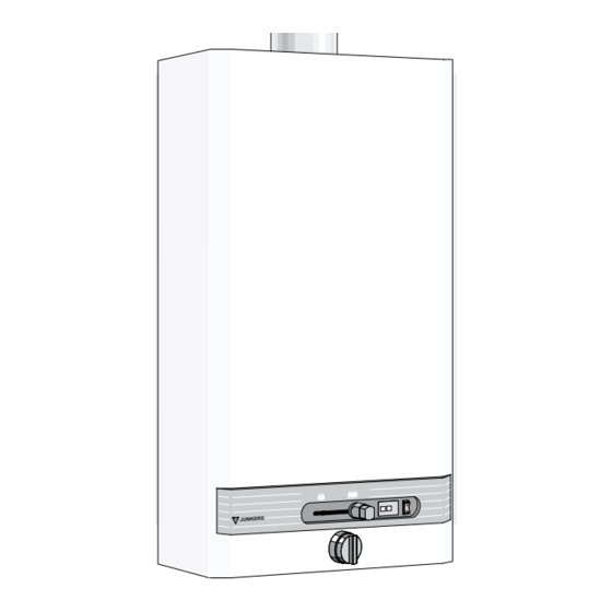
Gas Instantaneous Water Heaters
For your safety
If you smell gas:
1. Close gas isolating cock
2. Open windows
3. Do not actuate any electrical switches
4. Extinguish naked flames
5. Contact gas authorities immediately
Do not store or use flammable materials or liquids
near the appliance.
Do not place articles on or against this appliance.
Approved for indoor installation only.
-
THE APPLIANCE MAY ONLY BE INSTALLED BY AN AUTHORISED PERSON.
-
Perfect functioning of the appliance is guaranteed only if this specification and the operating instructions are followed.
-
The customer shall be provided with these installation instructions.
-
The fitter shall explain the function and operation of the appliance to the customer.
-
Servicing may only be carried out by authorised personnel.
-
Installation in a marine environment should be avoided.
-
Install in accordance with AS5601, AS/NZS3500.4.2, NZS5261 and all local building, water and gas fitting regulations.
-
Not suitable for pool or SPA application.
-
Failure to install the appliance in accordance with these installation instructions may void warranty.
WR 250 -8 K..G..
WR 325 -8 K..G..
WR 400 -8 K..G..
with Hydropower Ignition
Advertisement

Related Manuals for Bosch WR 250 -8 K..G Series


Summary of Contents for Bosch WR 250 -8 K..G Series
- Page 1 Installation and Operating Instructions Gas Instantaneous Water Heaters WR 250 -8 K..G.. For your safety WR 325 -8 K..G.. If you smell gas: 1. Close gas isolating cock WR 400 -8 K..G.. 2. Open windows 3. Do not actuate any electrical switches 4.
- Page 2 Index Page Page Description of Appliances ......... 2 Water Supply ..............5 Equipment ............... 2 Gas Connection ............5 Type Overview ..............2 Flue ................... 5 Connecting Measurements ......... 3 Commissioning ............... 5 Constructional Details ..........3 HDG Functioning ............5 Wiring Diagram ..............
- Page 3 Connecting Measurements 1 Front cover 2 Gas control slide 3 Water flow selector 4 Gas connection 5 Draught diverter 6 Chimney with draught diverter 7 Heat exchanger 8 Gas valve assembly 9 Ignition unit 10 Water valve assembly 11 Led failure indicator 12 Led indicator main burner condition Dimensions...
-
Page 4: Wiring Diagram
Wiring Diagram 1 - Servo gas valve 2 - Membrane valve 3 - Pilot gas valve 4 - Sensor electrode 5 - Sparking plug 6 - Temperature limiter 7 - Ignition unit 8 - Hydrogenerator 9 - Switch 10 - Led failure indicator 11 - Led indicator main burner condition Diagram 3 Technical Data... -
Page 5: Removal Of Front Shell 5
Installation compliance with pertinent regulations to be used. Cold water inlet (right) and hot water outlet (left) are marked by arrows on the water valve housing. Install in accordance with AS5601, AS/NZS3500.4.2, Use only Gate Valve or Full Flow Ball Valve. Non-Return NZS5261 and all local building, water and gas fitting regu- Valves MUST NOT BE USED. -
Page 6: Conversion To Other Gases
Gas burner pressure adjustment for minimum output (see clause 4.3, section 8) Gas inlet pressure adjustment Turn off gas supply. Remove inlet test point screw A. Attach U tube manometer. Turn on gas supply and start up appliance in accordance with operating instructions. -
Page 7: Fault Finding
Re-commissioning after repairs to the gas supply Frost Protection Purge gas piping of air. Trapped air can result in the pilot In areas where the atmospheric temperature drops below burner failing to light within 30-40 seconds. In that case, 0°C, the heater must be drained to prevent damage due to turn off the hot water tap and then turn it on again. -
Page 8: Operating Guide - Quick Reference
Operating Guide - Quick Reference Purge all water and gas pipes before operating. Turn off all water taps before adjusting appliance. Starting and shutting off the appliance To switch the appliance, turn the To shut off the appliance, turn the on/off switch to position "1"... - Page 9 The warranty period commences from the purchase date. Claims for warranty will only be accepted upon suitable proof of purchase submitted to Robert Bosch (Australia) Pty. Ltd. or an approved Bosch Service Agent authorised to carry out warranty repairs.