NEC LT260 User Manual
Hide thumbs
Also See for LT260:
- Important information manual (38 pages) ,
- Installation manual (7 pages) ,
- User manual (151 pages)
Table of Contents
Advertisement
Quick Links
CD-ROM version
Portable Projector
LT260/LT240/LT220
User's Manual
About this user's manual
The fastest way to get started is to take your time and do every-
thing right the first time. Take a few minutes now to review the
user's manual. This may save you time later on. At the begin-
ning of each section of the manual you'll find an overview. If the
section doesn't apply, you can skip it.
http://www.pureglare.com.au
Advertisement
Table of Contents

Related Manuals for NEC LT260


Summary of Contents for NEC LT260
- Page 1 CD-ROM version Portable Projector LT260/LT240/LT220 User’s Manual About this user's manual The fastest way to get started is to take your time and do every- thing right the first time. Take a few minutes now to review the user's manual. This may save you time later on. At the begin- ning of each section of the manual you'll find an overview.
-
Page 2: Introduction To The Projector
• The LT260/LT240/LT220 projector provides wired and wireless net- working. When using as a wireless LAN projector, no physical signal cable connection to a PC is required.* A wireless LAN card is required. The NEC optional wireless LAN card is ∗ available. (SWL-2100N-N... - Page 3 • An image can be projected from in front or behind a screen, and the projector can even be installed on the ceiling. • NEC’s exclusive Advanced AccuBlend intelligent pixel blending tech- nology - an extremely accurate image compression technology - of- fers a crisp image with UXGA (1600 1200) resolution* •...
- Page 4 INTRODUCTION Introduction to the Projector NOTE: Composite video standards are as follows: NTSC: U.S. TV standard for video in U.S. and Canada. PAL: TV standard used in Western Europe. PAL-N: TV standard used in Argentine, Paraguay and Uruguay. PAL-M: TV standard used in Brazil. PAL60: TV standard used for NTSC playback on PAL TVs.
- Page 5 INTRODUCTION Introduction to the Projector • The supplied remote control can be used without a cable, and you can even use the remote control to operate your PC's mouse wirelessly from across the room with the built-in remote mouse function. •...
-
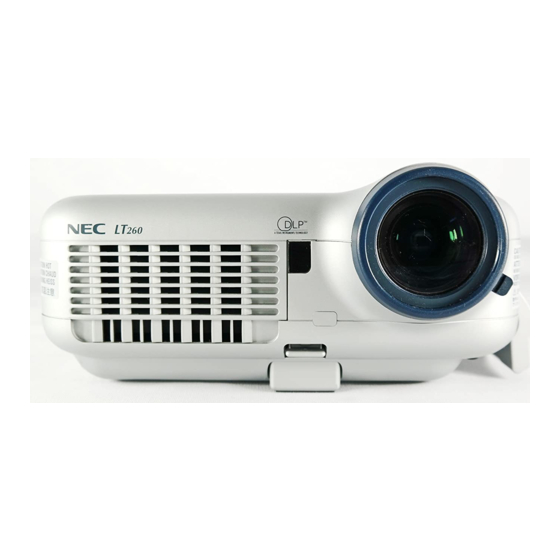
Page 6: Part Names Of The Projector
INTRODUCTION Part Names of the Projector Part Names of the Projector Focus Ring (See page E-44) Remote Sensor Controls (See page E-20) (See page E-8) Ventilation (inlet) Ventilation (outlet) Built-in Security Slot Heated air is exhausted from here Zoom Lever (See page E-44) Adjustable Tilt Foot Lever Carrying Handle... - Page 7 INTRODUCTION Part Names of the Projector PC Card Eject Button Monaural Speaker (2W) PC Card Slot Lamp cover (See page E-118) Ventilation (outlet) Remote Sensor Lamp cover screw (See page E-20) Rear Foot Rear Foot Rotate to make the projector level. (See page E-44) AC Input Main Power Switch...
-
Page 8: Top Features
INTRODUCTION Part Names of the Projector Top Features 1.POWER Button (ON / STAND BY) Use this button to turn the power on and off when the main power is supplied and the projector is in standby mode. NOTE: To turn on or off the projector, press and hold this button for a mini- mum of two seconds. - Page 9 INTRODUCTION Part Names of the Projector Top Features 4. SOURCE Button Use this button to select a video source such as a PC, VCR, DVD player, Viewer (PC card), or LAN. Press and release this button quickly to display the Source List. Each time this button is pressed for a minimum of TWO seconds, the input source will change as follows: RGB1 →...
- Page 10 INTRODUCTION Part Names of the Projector Top Features : Use these buttons to change the level of a selected menu item. A press of the button executes the selection. When the menus or the Viewer tool bar is not displayed, these buttons can be used to select a slide, or to move the cursor in Folder List or Slide List.
-
Page 11: Terminal Panel Features
INTRODUCTION Part Names of the Projector Terminal Panel Features Terminal Panel Features 10 11 3 5 1. RGB IN 1 / Component Input Connector (Mini D-Sub 15 Pin) Connect your computer or other analog RGB equipment such as IBM compatible or Macintosh computers. Use the supplied RGB cable to connect to your computer. - Page 12 Use this port to connect your PC to control your projector via a serial cable. This enables you to use your PC and serial communication pro- tocol to control the projector. The NEC optional serial cable (CA03D) is required to use this port. You can also control the projector by using Dynamic Image Utility 2.0 included on the supplied CD-ROM.
- Page 13 USB cable. You can operate your computer's mouse functions from the remote control. 12. PC CARD Eject Button Press to eject a PC card partially. 13. PC CARD Slot Insert a PC card, commercially available LAN card or NEC optional wireless LAN card here. E-13 http://www.pureglare.com.au...
-
Page 14: Part Names Of The Remote Control
INTRODUCTION Part Names of the Remote Control Part Names of the Remote Control NOTE: If you are using a Macintosh com- puter, you can click either the right-click or left-click button to activate the mouse. 1. Infrared Transmitter Direct the remote control toward the remote sensor on the projector cabinet. - Page 15 INTRODUCTION Part Names of the Remote Control 6. VIDEO Button Press this button to select an NTSC, PAL, PAL-N, PAL-M, PAL60, SECAM or NTSC4.43 compatible video source from a VCR, DVD player, or laser disc player. 7. S-VIDEO Button Press this button to select an S-Video source from a VCR. 8.
- Page 16 INTRODUCTION Part Names of the Remote Control 13. SELECT (Mouse) Button When you are in the Computer mode, these buttons work as a com- puter mouse. When you are in the Projector mode, which is indicated by lighting the PJ button. See page E-53. : Use these buttons to select the menu of the item you wish to adjust.
- Page 17 INTRODUCTION Part Names of the Remote Control 17. ASPECT Button Press this button to display the Aspect Ratio select screen. See page E-86. 18. FREEZE Button This button will freeze a picture. Press again to resume motion. 19. 3D REFORM Button Press this button to enter 3D Reform to correct the keystone (trapezoi- dal) distortion, and make the image square.
- Page 18 INTRODUCTION Part Names of the Remote Control 25. PICTURE MUTE Button This button turns off the image and sound for a short period of time. Press again to restore the image and sound. NOTE: When the menu is displayed, a press of this button mutes an image and sound without turning off the menu.
-
Page 19: Battery Installation
INTRODUCTION Part Names of the Remote Control Battery Installation 1. Press firmly and slide the battery cover off. 2. Remove both old batteries and install new ones (AA). Ensure that you have the batteries' polarity (+/-) aligned correctly. 3. Slip the cover back over the batteries until it snaps into place. Do not mix different types of batteries or new and old batteries. -
Page 20: Remote Control Precautions
INTRODUCTION Part Names of the Remote Control Remote Control Precautions • Handle the remote control carefully. • If the remote control gets wet, wipe it dry immediately. • Avoid excessive heat and humidity. • If you will not be using the remote control for a long time, remove the batteries. -
Page 21: Installation And Connections
INSTALLATION AND CONNECTIONS This section describes how to set up your projector and how to connect video and audio sources. To the wall outlet. Your projector is simple to set up and use. But before you get started, you must first: z Set up a screen and the projector. -
Page 22: Setting Up The Screen And The Projector
INSTALLATION AND CONNECTIONS Setting Up the Screen and theProjector Setting Up the Screen and the Projector Selecting a Location The further your projector is from the screen or wall, the larger the image. The minimum size the image can be is approximately 30" (0.8 m) mea- sured diagonally when the projector is roughly 4 feet (1.3 m) from the wall or screen. -
Page 23: Throw Distance And Screen Size
INSTALLATION AND CONNECTIONS Setting Up the Screen and theProjector Throw Distance and Screen Size The following shows the proper relative positions of the projector and screen. Refer to the table to determine the position of installation. Distance Chart Screen Width Screen Diagonal Screen Height Screen center... - Page 24 INSTALLATION AND CONNECTIONS Setting Up the Screen and theProjector <LT260> B = Vertical distance between lens center and screen center C = Throw distance D = Vertical distance between lens center and bottom of screen α = Throw angle NOTE: Distances may vary +/-5%.
- Page 25 INSTALLATION AND CONNECTIONS Setting Up the Screen and theProjector <LT240> B = Vertical distance between lens center and screen center C = Throw distance D = Vertical distance between lens center and bottom of screen α = Throw angle NOTE: Distances may vary +/-5%. α...
- Page 26 INSTALLATION AND CONNECTIONS Setting Up the Screen and theProjector <LT220> B = Vertical distance between lens center and screen center C = Throw distance D = Vertical distance between lens center and bottom of screen α = Throw angle NOTE: Distances may vary +/-5%. α...
-
Page 27: Reflecting The Image
Using a mirror to reflect your projector's image enables you to enjoy a much larger image. Contact your NEC dealer if you need a mirror. If you're using a mirror and your image is inverted, use the MENU and SELECT... -
Page 28: Making Connections
INSTALLATION AND CONNECTIONS Making Connections Wiring Diagram Monitor Document Camera VCR, DVD Player or LaserDisc Player To video, S-video, and au- dio inputs on the projector. RGB Signal cable (supplied) Optional 15-pin-to-RCA To mini D-Sub 15-pin connector on the pro- (female) 3 cable jector. - Page 29 SCART is a standard European audio-visual connector for TVs, VCRs and DVD players. It is also referred to as Euro-connector. NOTE: The ADP-SC1 SCART adapter is obtainable from your NEC dealer in Europe. Contact your NEC dealer in Europe for more information.
-
Page 30: Connecting Your Pc Or Macintosh Computer
INSTALLATION AND CONNECTIONS Making Connections Connecting Your PC or Macintosh Computer AUDIO IN RGB IN1 RGB IN2 RGB signal cable (supplied) To mini D-Sub 15-pin connector on the Audio cable (not supplied) projector. It is recommended that you use a commercially available distribution am- plifier if connecting a signal cable longer than the supplied one. - Page 31 4. If the projector goes blank after a period of inactivity, it may be caused by a screen saver installed on the computer you've connected to the pro- jector. NOTE: The LT260/LT240/LT220 is not compatible with video decoded outputs of NEC ISS-6020 and ISS-6010. E-31...
-
Page 32: Connecting An External Monitor
INSTALLATION AND CONNECTIONS Making Connections Connecting an External Monitor RGB OUT You can connect a separate, external monitor to your projector to simulta- neously view on a monitor the RGB analog image you're projecting. To do 1. Turn off the power to your projector, monitor and computer. 2. - Page 33 INSTALLATION AND CONNECTIONS Making Connections Connecting Your Video Equipment Connecting Your DVD Player RGB IN1 or IN2 Optional 15-pin-to-RCA (female) 3 cable (ADP-CV1) Audio Equipment Component video RCA 3 cable AUDIO IN (not supplied) DVD player AUDIO OUT COMPONENT OUT Audio cable (not supplied) You can connect your projector to a DVD player with component output or Video output.
- Page 34 INSTALLATION AND CONNECTIONS Making Connections Connecting Your VCR or Laser Disc Player VIDEO IN S-VIDEO IN S-video cable (not supplied) Video cable (not supplied) Audio equipment AUDIO IN VCR/ Laser disc player AUDIO OUT S-VIDEO OUT VIDEO OUT Audio cable (not supplied) Use common RCA cables (not provided) to connect your VCR, laser disc player or document camera to your projector.
- Page 35 INSTALLATION AND CONNECTIONS Making Connections 3. Turn on the projector and the VCR or laser disc player. NOTE: Refer to your VCR or laser disc player owner's manual for more informa- tion about your equipment's video output requirements. NOTE: An image may not be displayed correctly when a Video or S-Video source is played back in fast-forward or fast-rewind via a scan converter.
-
Page 36: Connecting The Supplied Power Cable
INSTALLATION AND CONNECTIONS Making Connections Connecting the Supplied Power Cable Connect the supplied power cable to the projector. First connect the supplied power cable's three-pin plug to the AC IN of the projector, and then connect the other plug of the supplied power cable in the wall outlet. -
Page 37: Projecting An Image
PROJECTING AN IMAGE (BASIC OPERATION) This section describes how to turn on the projector and to project a picture onto the screen. Turning on the Projector NOTE: • When plugging in or unplugging the supplied power cable, make sure that the main power switch is pushed to the off[O] position. - Page 38 PROJECTING AN IMAGE Turning on the Projector Note on Startup screen (Menu Language Select screen) When you first turn on the projector, you will get the Startup screen. This screen gives you the opportunity to select one of the seven menu lan- guages: English, German, French, Italian, Spanish, Swedish and Japa- nese.
- Page 39 PROJECTING AN IMAGE Turning on the Projector 3. The Basic menu will be displayed in the language you have selected. SELECT To close the menu, press the CANCEL button. After this has been done, you can proceed to the advanced menu opera- tion.
-
Page 40: Selecting A Source
PROJECTING AN IMAGE Selecting a Source Selecting the computer or video source Using the Remote Control POWER VIDEO S-VIDEO RGB1 RGB2 AUTO ADJ. LASER Press any one of the RGB1, RGB2, VIDEO, S-VIDEO or VIEWER buttons. ASPECT FREEZE 3D REFORM HELP POINTER VIEWER... - Page 41 PROJECTING AN IMAGE Selecting a Source Detecting the Signal Automatically Press and hold the SOURCE button for a minimum of 2 seconds, the projector will search for the next available input source. Each time you press and hold the SOURCE button, the input source will change as follows: →...
-
Page 42: Adjusting The Picture Size And Position
PROJECTING AN IMAGE Adjusting the Picture Size and Position Place your projector on a flat level surface and ensure that the projector is square to the screen. Lift the front edge of the projector to center the image vertically. Move the projector left to center the image horizontally on the screen. Use the 3D REFORM feature for proper adjustment. -
Page 43: Adjust The Tilt Foot
PROJECTING AN IMAGE Adjusting the Picture Size and Position Adjust the Tilt Foot q Lift the front edge of the projector. Adjustable Tilt Foot Lever Adjustable Tilt Foot w Push up the Adjustable Tilt Foot Lever on the front of the projector to extend the adjustable tilt foot (maximum height). - Page 44 PROJECTING AN IMAGE Adjusting the Picture Size and Position The rear foot height can be changed. Rotate the rear foot to the desired height, but the vertical distance from the bottom to the desk or floor should be 1" (25 mm) to make the projector horizontal on the flat surface. Down Down * If the projected image does not appear square to the screen then...
- Page 45 PROJECTING AN IMAGE Correcting the Horizontal and Vertical Keystone Distortion (3D Reform) Use the 3D Reform feature to correct keystone (trapezoidal) distortion to make the top or bottom and the left or right side of the screen longer or shorter so that the projected image is rectangular. You can also use a mouse to correct the Cornerstone distortion.
- Page 46 PROJECTING AN IMAGE 4. Use the SELECT button to select one icon which points in the direction you wish to move the projected image frame. Screen 5. Press the ENTER button. 6. Use the SELECT button to move the projected image frame as shown on the example.
- Page 47 PROJECTING AN IMAGE 9. Press the SELECT button to highlight the [OK] and press the ENTER button. This completes the keystone correction. Selecting “Cancel” will return to the adjustment screen without saving changes (Step 3). Selecting "Reset" will return to the factory default. Selecting "Undo"...
-
Page 48: Optimizing Rgb Picture Automatically
PROJECTING AN IMAGE Optimizing RGB Picture Automatically Adjusting the Image Using Auto Adjust Optimizing RGB image automatically Press the Auto Adjust button to optimize an RGB image automatically. [Poor picture] AUTO ADJ. [Normal picture] Press the Auto Adjust button to fine-tune the computer image or to remove any vertical banding that might appear and to reduce video noise, dot interference or cross talk (this is evident when part of your image appears to be shimmering). -
Page 49: Turning Up Or Down Volume
PROJECTING AN IMAGE Turning Up or Down Volume Sound level from the speaker and the AUDIO OUT mini jack on the projec- tor can be adjusted. VOLUME Volume bar increase volume decrease volume Using the Laser Pointer You can use the laser to draw your audience's attention to a red dot that you can place on any object. -
Page 50: Setting The Function Switch
PROJECTING AN IMAGE Setting the function switch There are two switches on the bottom of the battery case: an applicable projector selector switch (1) and laser enable/dis- able switch (2). Check the projector be- ing used and decide whether to enable or disable laser, then set these switches as necessary using the tip of a thin ball- point pen. -
Page 51: Turning Off The Projector
PROJECTING AN IMAGE Turning off the Projector To turn off the projector: First press the POWER (ON/STAND BY) but- POWER VIDEO S-VIDEO RGB1 RGB2 ton on the projector cabinet or the POWER OFF AUTO ADJ. LASER button on the remote control for a minimum of two seconds. -
Page 52: Convenient Features
CONVENIENT FEATURES Using the Remote Mouse Function The built-in remote mouse function enables you to operate your computer's mouse functions from the remote control (Computer mode). It is a great convenience for clicking through your computer-generated presentations. To return to the projector operation mode (Projector mode), press the PJ button (lit red). - Page 53 CONVENIENT FEATURES Using the Remote Mouse Function Switching operation mode between computer and pro- jector The three shaded buttons shown on the drawing work as a computer mouse in the Computer mode. In the Computer mode the PJ button is not lit. Works as a mouse Works as the Select button for your computer.
- Page 54 CONVENIENT FEATURES Using the Remote Mouse Function • When the MENU button is pressed, the PJ button lights red to indi- cate that you are in the Projector mode, which allows the projector menu operation using the three buttons. • When the POINTER button is pressed, the PJ button lights red to indicate that you are in the Projector mode and that the SELECT button works as a moving button for the POINTER or magni- fied image.
-
Page 55: Turning Off The Image And Sound
CONVENIENT FEATURES Turning Off the Image and Sound PIC-MUTE Press the Picture Mute button to turn off the image and sound for a short period of time. Press again to restore the image and sound. Freezing a Picture FREEZE Press the Freeze button to freeze a picture. Press again to resume motion. -
Page 56: Enlarging And Moving A Picture
CONVENIENT FEATURES Enlarging and Moving a Picture You can enlarge the area you want up to 400 percent. To do so: 1. Press the Pointer button to display the pointer. POINTER 2. Move the pointer to the area you want to enlarge. SELECT 3. - Page 57 CONVENIENT FEATURES Getting the On-line Help You get the contents about Help. HELP SELECT Display Help Exit Help E-57 http://www.pureglare.com.au...
-
Page 58: Using A Usb Mouse
CONVENIENT FEATURES Using a USB Mouse Using a USB mouse gives you a smooth operation. A commercially avail- able USB mouse is required. Type A NOTE: There may be some brands of USB mouse that the projector does not support. Operate the Menus using the USB mouse Mouse Cursor When connecting a USB mouse to the projector, you get a mouse cur-... -
Page 59: Changing Background Logo
CONVENIENT FEATURES Examples Click (or press and hold) the mouse button to adjust the bright- ness. Or click and drag the mouse button on the slide bar horizontally to adjust it. To save the adjustments, click . The display is closed. If you click anywhere in the background while displaying adjustment and setting menu or dialog box, you will get the main menu at the clicking point. - Page 60 * Once you have changed the background from the NEC logo to an- other, you cannot return the logo to background even by using Factory Default. To do so, repeat the above steps. The NEC logo file is included on the supplied CD-ROM NEC Projector User Supportware (/Logo/ nec_b_x.jpg).
- Page 61 CONVENIENT FEATURES Making Freehand Drawings on a Projected Image (ChalkBoard) The ChalkBoard feature allows you to write and draw messages on a pro- jected image. NOTE: The ChalkBoard feature is available only when a USB mouse is used. From the menu, select [Tools] → [ChalkBoard] to display the ChalkBoard tool bar that cotains the following icons.
-
Page 62: Using The Viewer
USING THE VIEWER NOTE: To use the Viewer, first you need to create presentation materials on your PC using the Dynamic Image Utility 2.0 contained on the supplied NEC Projec- tor User Supportware CD-ROM. For installation, see the printed Application Guide. For creating presentation materials, see the Slide show function on the on-line manual of the Dynamic Im- age Utility 2.0. -
Page 63: Inserting And Removing A Pc Card
USING THE VIEWER Simple utility software (for computer) • Dynamic Image Utility 2.0 operable on Windows 98/Me/XP/2000 • Slides can be created by capturing the currently displayed image • Control screen for displaying lists of slides and editing * Microsoft, Windows and PowerPoint are registered trademarks of Microsoft Corporation. -
Page 64: Pc Card Type
USING THE VIEWER Removing the PC Card Press the eject button. The PC card pops out a little. Grasp the edges of the PC card and pull it out. NOTE: Do not eject the PC card while its data is being accessed. Eject button Direction for Inserting the PC Card The PC card has a top and bottom and must be inserted into the PC card... - Page 65 USING THE VIEWER Operating the Viewer Function from the Projector (playback) This section describes the operation for showing slides of presentation documents created using the Viewer function with the projector. It is also possible to make slides directly from the images projected with the projec- tor.
- Page 66 USING THE VIEWER Play .... Plays back automatically or manually depending on the setting on Viewer Options of the menu. This allows you to move on to the next slide when "Manual Play" is selected. Stop .... This allows you to stop Auto Play while you are playing back and to resume playing from the selected slide or folder when "Auto Play"...
- Page 67 USING THE VIEWER When the tool bar is not displayed: Press the FOLDER LIST button or the SLIDE LIST button on the remote control to display folders or from a PC card in the projector's PC Card slot. Multi cursor (blue marks) Folder Folder Folder...
-
Page 68: Auto Play Mode
USING THE VIEWER NOTE: You can also use the button on the remote control to select folders or slides. If you use the button on the remote control for Viewer operation, press the PJ button to switch to the Projector mode and the PJ button lights red. Works as the Select button SELECT on the projector. -
Page 69: Viewing Digital Images
USING THE VIEWER Viewing Digital Images Digital images can be played with the Viewer if the following conditions are met: • If the image can be stored on an MS-DOS format PC card • If the image can be stored in a format supported by the Viewer. With the Viewer, images on the card are searched for in directories and images in JPEG or BMP format are recognized as slides. - Page 70 USING THE VIEWER NOTE: * Unless a PC card is inserted into the PC Card slot of the projector, the Cap- ture feature is not available. * The "Card Error" display means that the free space of the PC card is insuffi- cient for saving images.
- Page 71 USING THE VIEWER Exit ..... Exits the Capture function. Another option to exit the Cap- ture function is to press MENU or CANCEL button on the remote control or projector cabinet. NOTE: You can compress a captured file (JPEG) using the Capture Options in the Setup dialog.
-
Page 72: Deleting Captured Images
USING THE VIEWER Deleting Captured Images Using the Delete button on the tool bar for Viewer can delete captured images. Prev Play Jump Setup View Drag Next Stop Select Delete To delete captured images: 1. Select Viewer and display a folder list of captured images. 2. -
Page 73: Basic Menu Operation
USING ON-SCREEN MENU Basic Menu Operation Using the Menus NOTE: The on-screen menu may not be displayed correctly while interlaced mo- tion video image is projected. 1. Press the MENU button on the remote control or projector cabinet to display the Basic, Advanced or Custom Menu. NOTE: When using a USB mouse, click the mouse button to display the menu. -
Page 74: Customizing The Menu
USING ON-SCREEN MENU Basic Menu Operation Customizing the Menu The Custom menu can be customized to meet your requirements. Select- ing a menu item from the "Custom Menu Edit" list, allows you to custom tailor the menu items to your needs. 1. - Page 75 USING ON-SCREEN MENU Basic Menu Operation NOTE: If the "Advanced Menu" item has been selected on the Menu mode, you get the "Confirmation Change Menu" upon completion of "Custom Menu" edit- ing. In this case, selecting "Yes" then "Enter" will close all the menus and apply the changes from the Advanced menu to the Custom Menu.
-
Page 76: Menu Tree
USING ON-SCREEN MENU Basic Menu Operation Menu tree Advanced Menu RGB1 Source Select RGB2 Picture Video Volume S-Video User1 Image Options Viewer User2 Picture Management User3 Projector Options more Entry List Tools Help Picture Brightness, Contrast, Color, Factory Default Hue, Sharpness Volume Aspect Ratio 4:3, Letter Box, Wide Screen, Crop / 4:3... - Page 77 USING ON-SCREEN MENU Basic Menu Operation Advanced Menu Cornerstone Source Select Keystone Horizontal, Vertical Picture Volume Menu Image Options 3D Reform Page 1 Picture Management Menu Language English, Deutsch, Projector Options Setup Français, Italiano, Tools Screen Español, Svenska Help LAN Mode Factory Default Password Menu Mode...
-
Page 78: Table Of Contents
USING ON-SCREEN MENU Basic Menu Operation Screen Type 4:3, 16:9 / Position LAN Mode Advanced Menu IP Address Source Select Picture Automatic 3D Reform Volume Manual IP Address, Menu Subnet Mask,Gateway Image Options Setup Picture Management Projector Name Screen Projector Options DNS Configuration LAN Mode Domain Name... -
Page 79: Menu Elements
USING ON-SCREEN MENU Basic Menu Operation Menu Elements Help Button Title bar Close Button Highlight Radio button OK Button Cancel Button Solid triangle Check box Drag Slide bar Tool bar Menu windows or dialog boxes typically have the following elements: Title bar ... - Page 80 USING ON-SCREEN MENU Basic Menu Operation Check box ..Place a checkmark in the square box to turn the option Slide bar ..Indicates settings or the direction of adjustment. OK button ..Press to confirm your setting. You will return to the pre- vious menu.
-
Page 81: Source Select
USING ON-SCREEN MENU Menu Descriptions & Functions Source Select Selecting a Source Enables you to select a video source such as a VCR, DVD player, laser disc player, computer or document camera depending on what is con- nected to your inputs. Press the SELECT button on the projector cabinet or on your remote control to highlight the menu for the source you want to project. - Page 82 USING ON-SCREEN MENU Menu Descriptions & Functions NOTE: Even if you switch the current Viewer source to another source, the cur- rent slide is retained. When you return back to the Viewer, you will get the slide that has been retained. A launcher will appear when you press the MENU button. A press of the MENU button displays the toolbar;...
- Page 83 USING ON-SCREEN MENU Menu Descriptions & Functions Selects a signal from a LAN card plugged into the projector's card slot. Entry List Displays the list of the entry signals. Use the SELECT buttons on your remote control or the projector cabinet to select the signal and press the ENTER button on the remote control or the projector cabinet to display the Entry Edit Command screen.
- Page 84 USING ON-SCREEN MENU Menu Descriptions & Functions Input Terminal: Change the input terminal. RGB1 and RGB2 are avail- able for RGB signal; Video and S-Video are available for composite signal. Source List: Set signal selection method. Lock: Set so that the selected signal cannot be deleted when "All De- lete"...
-
Page 85: Volume
USING ON-SCREEN MENU Menu Descriptions & Functions Picture (not available for Viewer and LAN) Adjusting Brightness, Contrast, Color, Hue, and Sharpness Brightness ..Adjusts the brightness level or the back raster inten- sity. Contrast ..Adjusts the intensity of the image according to the in- coming signal. -
Page 86: Image Options
USING ON-SCREEN MENU Menu Descriptions & Functions Image Options Selecting Aspect Ratio (not available for Viewer and LAN) Aspect Ratio allows you to select the best Aspect mode to display your source image. When screen size 4:3 is selected for the source, the following selec- tions will display: 4:3 .... - Page 87 USING ON-SCREEN MENU Menu Descriptions & Functions NOTE: During 3D Reform adjustment, "Aspect Ratio" may not be available. Should this happen, first reset the 3D Reform data and then do setting again. Second repeat the 3D Reform adjustment. Changing the aspect ratio can limit 3D Reform in its adjustable range. Input Signal Screen...
- Page 88 USING ON-SCREEN MENU Menu Descriptions & Functions Clock ....Use this item to fine tune the computer image or to remove any vertical banding that might appear. This function adjusts the clock frequencies that eliminate the horizontal banding in the image. Press the SELECT buttons until the banding disappears.
- Page 89 USING ON-SCREEN MENU Menu Descriptions & Functions NOTE: * When "Resolution" is set to "Native", "Overscan", "3D Reform", "Aspect Ratio" and "Screen" are not available. * While you are displaying an image with higher resolution than the projector’s native resolution, "Resolution" is not available. Selecting Overscan Percentage Select overscan percentage (0%, 5%, 10% and 25%) for signal.
-
Page 90: Picture Management
USING ON-SCREEN MENU Menu Descriptions & Functions Picture Management This option allows you to adjust neutral tint for yellow, cyan or magenta. There are 5 factory presets optimized for various types of images, or you can set 4 user adjustable settings. Presentation .. - Page 91 USING ON-SCREEN MENU Menu Descriptions & Functions Selecting Color Correction (not available on LT220) Adjusts red, green, blue, yellow, magenta, cyan and color gain each independently to correct the tint on whole screen. Selecting White Peaking Adjust the brightness of the white areas by using the slide bar. As the picture becomes dim, it looks more natural.
-
Page 92: Projector Options
USING ON-SCREEN MENU Menu Descriptions & Functions Selecting Base Setting This feature allows you to use color correction or gamma values as reference data to optimize for various types of images. You can select one of the following five settings. •... - Page 93 USING ON-SCREEN MENU Menu Descriptions & Functions Menu Allows you to set preferences for the on-screen menu. Press "OK" to save your changes for all the features of Page 1 and Page 2. [Page1] Selecting Menu Language [Language]: You can choose one of seven languages for on-screen instructions. The options are: English, German, French, Italian, Spanish, Swed- ish and Japanese.
- Page 94 USING ON-SCREEN MENU Menu Descriptions & Functions Selecting Menu Display Time : This option allows you to select how long the projector waits after the last touch of a button to turn off the menu. The preset choices are "Manual", "Auto 5 sec", "Auto 15 sec", and "Auto 45 sec".
- Page 95 USING ON-SCREEN MENU Menu Descriptions & Functions Setup Enables you to set operating options. Press "OK" to save your changes for all the features of Page1, Page2, Page3, Page 4 and Page 5. [Page 1] Setting Lamp Mode to Normal or Eco [Lamp Mode]: This feature enables you to select two brightness mode of the lamp: Normal and Eco modes.
- Page 96 USING ON-SCREEN MENU Menu Descriptions & Functions Setting RGB 1 or 2 for RGB OUT [RGBOUT Terminal] This option allows you to determine which RGB source is output from the RGBOUT connector during Idle mode. Last .... The signal from the last RGB input will be output to the RGBOUT connector.
- Page 97 USING ON-SCREEN MENU Menu Descriptions & Functions Auto Play Interval: You can specify interval time between 5 and 300 seconds. NOTE: The Auto Play Interval time set on “Slide Show Settings” of the Dynamic Image Utility 2.0 overrides the one set here. Manual Play: Views a slide manually when the Viewer source is selected.
- Page 98 When "Auto Adjust" is set to "On", the projector automatically deter- mines the best resolution for the current RGB input signal to project an image using NEC's Advanced AccuBlend Intelligent Pixel Blend- ing Technology. The image can be automatically adjusted for position and stability;...
- Page 99 USING ON-SCREEN MENU Menu Descriptions & Functions Enabling Auto Start [Auto Start]: Turns the projector on automatically when the power cable is in- serted into an active power outlet and the main power switch is turned on. This eliminates the need to always use the "Power" but- ton on the remote control or projector cabinet.
- Page 100 USING ON-SCREEN MENU Menu Descriptions & Functions Enabling Idle Mode [Idle Mode]: The projector has two standby modes: Standby and Idle. Standby is the mode that allows you to put the projector in the standby condition which consumes less power than the idle mode. The pro- jector is preset for Standby at the factory.
- Page 101 USING ON-SCREEN MENU Menu Descriptions & Functions Last .... Sets the projector to default to the previous or last ac- tive input each time the projector is turned on. Auto .... Searches for an active source in order of RGB1 → RGB2 →...
-
Page 102: Setting Lan Mode
Consult with your network administrator about these settings. NOTE: A LAN card is required for LAN connection; NEC's optional wireless LAN card is available. For more information on inserting or ejecting a LAN card, see pages E-63 and 64. -
Page 103: Information
USING ON-SCREEN MENU Menu Descriptions & Functions Automatic ..Automatically assigns an IP address to the projector from a DHCP server. Manual .... Provides a space for you to register the IP address or subnet mask number obtained from your network ad- ministrator. -
Page 104: Network Type
USING ON-SCREEN MENU Menu Descriptions & Functions Network Type (required for wireless only) Mode: Select communication method when using wireless LAN. Infrastructure ... Select this option when communicating with one or more equipment connected to the wireless or wired LAN network via an access point. 802.11 Ad Hoc Select this option when using the wireless LAN to com- municate with a computer in a one-to-one correspon- dence. -
Page 105: Tx Rate
USING ON-SCREEN MENU Menu Descriptions & Functions SSID (Network name): Enter an identifier (SSID) for wireless LAN when selecting [Infrastruc- ture] or [802.11 Ad Hoc] in [Mode]. Communication can be done only with equipment whose SSID matches SSID for your wireless LAN. Up to 32 alphanumeric characters can be used. - Page 106 USING ON-SCREEN MENU Menu Descriptions & Functions WEP (for Wireless only) Select this option whether using the WEP (Wired Equivalent Privacy) key for encryption or not. To use encryption, specify WEP key. Disable .... Will not turn on the encryption feature. Your communi- cations may be monitored by someone.
-
Page 107: Mail
USING ON-SCREEN MENU Menu Descriptions & Functions Key1-4: Enter encryption key when selecting [64bit] or [128bit] in [WEP]. The key can also be set in hexadecimal digit. * Enter 0X(numeral and alphabet respectively) right in front of your key code. * Hexadecimal uses 0 to 9 and A to F. -
Page 108: Sender's Address
USING ON-SCREEN MENU Menu Descriptions & Functions Sample of a message sent from the projector: The lamp is at the end of its usable life. Please replace the lamp. Projector Name: X X X X Lamp Hour Meter: xxxx [H] Projector Usage: xxxxxx [H] Sender's Address: Specify the senders address. -
Page 109: Status
USING ON-SCREEN MENU Menu Descriptions & Functions Status Displays the status of the LAN settings. IP Address ..Indicates the IP address of the projector. Subnet Mask ... Indicates the subnet mask of the projector. MAC Address .. Indicates the MAC address of the LAN card. Setting a Password A password can be set for your projector to avoid operation by an unau- thorized person. - Page 110 USING ON-SCREEN MENU Menu Descriptions & Functions Entry To assign your password: NOTE: Up to 15 alphanumeric characters can be assigned. 1. Type a password. Highlight "Entry" and press the ENTER button. The "Enter the Password screen" will be displayed. Make sure that [ ] is highlighted and then press the ENTER button.
-
Page 111: Security
USING ON-SCREEN MENU Menu Descriptions & Functions Security The Security function enables you to protect your projector so that the projector will not project a signal unless you enter a keyword. There is also an option to lock the projector by using a registered PC card as a protect key. - Page 112 USING ON-SCREEN MENU Menu Descriptions & Functions To set up a keyword to enable the Security function without using a regis- tered PC card 1. Use the SELECT button to select “Keyword” and use the software keyboard to enter a keyword. NOTE: Please make a note of your keyword.
- Page 113 3. Enter your keyword in the Release Code input screen. You can view the projected image. NOTE: Do not forget your keyword. However, if you forget your keyword, NEC or your dealer will provide you with your Release Code. See more information at the end of this section.
- Page 114 The PC card data will be deleted. If you've lost your registered PC card, proceed as follows: NOTE: NEC or your dealer will provide you with your Release Code in ex- change for your registered keyword and Request Code. See more information at the end of this section.
- Page 115 USING ON-SCREEN MENU Menu Descriptions & Functions Tools Provides tools for setting sleep timer, capturing images, displaying files or changing your background logo in a PC Card and drawing. NOTE: The "Capture" and "PC Card Files" features are required for a PC card. Using Sleep Timer 1.
- Page 116 USING ON-SCREEN MENU Menu Descriptions & Functions Changing Background Logo: You can change the default background logo using the PC Card Files feature. NOTE: File size must be 256KB or less. Other file formats than JPEG and BMP are not available. See page E-59. Using ChalkBoard The ChalkBoard feature allows you to write and draw messages on a pro- jected image.
-
Page 117: Returning To Factory Default
USING ON-SCREEN MENU Menu Descriptions & Functions NOTE: The progress indicator shows the percentage of remaining bulb life. The value informs you of the amount of lamp and projector usage respectively. Remaining Lamp Time Display: When the remaining lamp time reaches 0, the Remaining Lamp Time bar indicator changes from 0% to 100 Hours and starts counting down. -
Page 118: Replacing The Lamp
(up to 2000 hours : Eco mode) of use, the lamp bulb may shatter, and pieces of glass may be scattered in the lamp housing. Do not touch them as the pieces of glass may cause injury. If this happens, contact your NEC dealer for lamp replacement. E-118 http://www.pureglare.com.au... -
Page 119: To Replace The Lamp
MAINTENANCE To replace the lamp: 1. Loosen the lamp cover screw until the screwdriver goes into a freewheel- ing condition and remove the lamp cover. The lamp cover screw is not removable. 2. Loosen the two screws securing the lamp housing until the screwdriver goes into a freewheeling condition. - Page 120 4. Insert a new lamp housing until the lamp housing is plugged into the socket. CAUTION Do not use a lamp other than the NEC replacement lamp (LT60LP). 5. Secure it in place with the two screws. Be sure to tighten the screws.
- Page 121 MAINTENANCE 8. After you install a new lamp, from the menu select [Projector Options] → [Setup] → [Page 4] → [Clear Lamp Hour Meter] to reset the lamp usage hours. If the projector will not be turned on after using 1600 hours (up to 2100 hours : Eco mode) of service, press and hold the [Help] button on the remote control for ten seconds or longer to reset the lamp time clock to zero.
- Page 122 Lens Protector The lens barrel has threads on the outside for mounting a commercially available lens protector (φ 62mm for LT260/LT220 and φ 72mm for LT240) to protect the lens from dirt, dust, scratches and damage. Note that both a lens protector and the supplied lens cap cannot be used at the same time.
-
Page 123: Troubleshooting
TROUBLESHOOTING This section helps you resolve problems you may encounter while setting up or using the projector. Power Indicator Indicator Condition Projector Condition Note The main power is off – Blinking light Green blinking 0.5 sec ON, The projector is getting ready Wait for a moment. -
Page 124: Lamp Indicator
TROUBLESHOOTING Lamp Indicator Indicator Condition Projector Condition Note Normal – Blinking light Lamp has reached its end of Replace the lamp. life. Lamp replacement mes- sage will be displayed. Steady light Lamp has been used beyond Replace the lamp. its limit. The projector will not turn on until the lamp is re- placed. - Page 125 TROUBLESHOOTING Common Problems & Solutions Problem Check These Items Does not turn on • Check that the power cable is plugged in and that the power button on the projector cabinet or the remote control is on. See pages E-36 and 37. •...
- Page 126 TROUBLESHOOTING When using the Viewer function Problem Check These Items No picture • Is “Viewer” selected from the Source menu? • Is the PC card seated in the PC Crad slot completely? • Are slide data stored in the PC card? •...
-
Page 127: Specifications
SPECIFICATIONS This section provides technical information about the LT260/LT240/LT220 Projector's performance Model Number LT260/LT240/LT220 Optical DMD™ Single Chip Digital Micromirror Device(DMD™) Resolution 1024 768 pixels (LT220: 800 600 pixels) up to UXGA with Advanced AccuBlend Lens Manual zoom and focus: LT260/LT220: F2.2 - 2.5... - Page 128 10.2" (W) 3.6" (H) 10.8" (D) 260mm (W) 92mm (H) 275mm (D) (not including protrusions) Net Weight LT260/LT220: 6.5 lbs / 2.9 kg LT240: 7.1 lbs / 3.2 kg Environmental Considerations Operational Temperatures : 41° to 95°F (5° to 35°C), 20% to 80% humidity...
-
Page 129: Cabinet Dimensions
APPENDIX Cabinet Dimensions 92 (3.6") 260 (10.24") 57 (2.24") * LT240: 319mm (12.56”) Unit = mm (inch) E-129 http://www.pureglare.com.au... - Page 130 APPENDIX Pin Assignments of D-Sub RGB Input Connector Mini D-Sub 15 Pin Connector Signal Level Video signal : 0.7Vp-p (Analog) Sync signal : TTL level * RGB 1 Input only Pin No. RGB Signal (Analog) YCbCr Signal Green or Sync on Green Blue Ground Ground...
-
Page 131: Compatible Input Signal List
APPENDIX Compatible Input Signal List Signal Resolution Frequency H. Refresh Rate Dot Clock ( Dots ) ( kHz ) ( Hz ) ( MHz ) NTSC – 15.734 – – 15.625 – SECAM – 15.625 – VESA 31.47 59.94 25.175 31.47 25.175 31.47... - Page 132 50 Interlaced – #:Images in above flagged with # are compressed with Advanced AccuBlend on LT260 and LT240. @:Images in above flagged with @ are compressed with Advanced AccuBlend on LT220. NOTE: Some composite sync signals may not be displayed correctly.
-
Page 133: Pc Control Codes And Cable Connection
APPENDIX PC Control Codes and Cable Connection PC Control Codes Function Code Data POWER ON POWER OFF INPUT SELECT RGB 1 INPUT SELECT RGB 2 INPUT SELECT VIDEO INPUT SELECT S-VIDEO INPUT SELECT VIEWER PICTURE MUTE ON PICTURE MUTE OFF SOUND MUTE ON SOUND MUTE OFF ON SCREEN MUTE ON... -
Page 134: Using Software Keyboard
APPENDIX Using Software Keyboard 1 to 0 and Characters ..Use to type in IP address or projector name SP ........Inserts a space BS ........Deletes one character backward ......... Returns to the previous ......... Advances to the next OK ........ -
Page 135: Operation Using An Http Browser
APPENDIX Operation Using an HTTP Browser Overview The use of HTTP server functions will allow control of the projector from a web browser without the installation of special software. Please be sure to use “Microsoft Internet Explorer 4.x” or a higher version for the web browser. (This device uses “JavaScript”... - Page 136 “HOSTS” file of the computer being used. Example 1: When the host name of the projector has been set to “pj.nec.co.jp”, http://pj.nec.co.jp/index.html is specified for the address or the entry column of the URL. Example 2: When the IP address of the projector is “192.168.73.1”,...
- Page 137 APPENDIX Structure of the HTTP Server Power: This controls the power of the projector. On ....Power is switched on. Off ....Power is switched off. Volume: This controls the volume of the projector...... Increments the volume adjustment value......
- Page 138 APPENDIX Picture: Controls the video adjustment of the projector. Brightness ... Increments the brightness adjustment value. Brightness ... Decrements the brightness adjustment value. Contrast ..Increments the contrast adjustment value. Contrast ..Decrements the contrast adjustment value. Color ... Increments the color adjustment value. Color ...
-
Page 139: Travelcare Guide
APPENDIX TravelCare Guide TravelCare - a service for international travelers This product is eligible for "TravelCare", NEC's unique international war- ranty. Please note that TravelCare coverage differs in part from coverage under the warranty included with the product. Services offered with TravelCare... - Page 140 5) Problems or damage caused by use in hot or humid places, in vehicles, boats or ships, etc. 6) Problems or damage caused by expendable supplies or devices con- nected to the product other than those designated by NEC. E-140 http://www.pureglare.com.au...
- Page 141 This list applies as of June 1, 2002. For the most up-to-date information, please refer to the websites of the service stations in the various countries on the List of TravelCare Outlets or to the NEC website at http://www.nec-pj.com. List of TravelCare Outlets In Europe NEC Europe, Ltd.
- Page 142 APPENDIX In North America NEC Solutions (America), Inc. Address: 1250 Arlington Heights Road, Itasca, Illinois 60143, U.S.A. Telephone: +1 800 836 0655 Fax Line: +1 800 356 2415 Email Address: vsd-tech-support@necsam.com WEB Address: http://www.necvisualsystems.com (Regions Covered) U.S.A. *, Canada* In Oceania NEC Australia Pty., Ltd.
- Page 143 Fax Line: +81 465 85 2393 Email Address: support_pjweb@nevt.nec.co.jp WEB Address: http://www.nec-pj.com (Regions Covered) Japan* NEC Hong Kong Ltd. Address: 11th Floor, Tower B, New Mandarin Plaza, 14 Science Museum Road, Tsim Sha Tsui East, Kowloon, Hong Kong Telephone: +852 2369 0335...
- Page 144 APPENDIX NEC Singapore Pte. Ltd Address: 401 Commonwealth Drive, #07-02, Haw Par Technocentre, Singapore 149598 Telephone: +65 6 273 8333 Fax Line: +65 6 274 2226 Email Address: daniel@rsc.necsin.nec.com.sg WEB Address: http://www.nec.com.sg (Regions Covered) Singapore Hyosung Data System, Ltd. Address:...
- Page 145 APPENDIX ABBA Electronics L.L.C. Address: Tariq Bin Ziyad Road, P.O.Box 327, Dubai, United Arab Emirates Telephone: +971 4 371800 Fax Line: +971 4 364283 Email Address: ABBA@emirates.net.ae (Regions Covered) United Arab Emirates Samir Photographic Supplies Address: P.O.Box 599, Jeddah 21421, Saudi Arabia Telephone: +966 2 6828219 Fax Line:...
- Page 146 P-1/ Date: TO: NEC or NEC's Authorized Service Station: (Company & Name with signature) Dear Sir (s), I would like to apply your TravelCare Service Program based on attached registration and qualification sheet and agree with your following conditions, and also the Service fee will be charged to my credit card account, if I don't return the Loan units within the specified period.
- Page 147 The 'Faulty unit' is sent or collected from the customer. It is repaired and returned within 10 days to the customer, excluding transport time. There may have a case, repair and return can't be done by NEC Autho- rized Service Station, because of shortage of spare parts due to same model is not sold in the territory.
- Page 148 3) Any fault in the attachments or associated products or components (whether or not supplied by NEC or its agents which do not form part of the Product covered by this warranty); 4) Any act of God, fire, flood, war, act of violence or any similar occur- rence;...
- Page 149 If Customer does not return the unit within the 12 calendar days, Cus- tomer will be charged the next highest cost up to and including the full list price to Credit Cards, which price will be informed by NEC Authorized Service Stations. Please see the attached listing of contacts for each country to arrange for pickup of the loan unit.