Electrolux W565H Service Manual
Washer extractor
Hide thumbs
Also See for W565H:
- Installation manual (44 pages) ,
- Operating manual (28 pages) ,
- Specifications (2 pages)

Related Manuals for Electrolux W565H


Summary of Contents for Electrolux W565H
-
Page 1: Service Manual
Service Manual Washer extractor W565H, W575H, W5105H, W5130H, W5180H, W5240H, W5300H Type W3... 438 9038-50/EN 2013.03.27 Original instructions... -
Page 3: Table Of Contents
Contents Contents 1 Symbols ..........................5 2 Technical data ........................6 2.1 Drawing ........................6 2.1.1 W565H, W575H, W5105H ..................6 2.1.2 W5130H ........................ 7 2.1.3 W5180H, W5240H, W5300H ................8 2.2 Technical data....................... 9 2.3 Connections........................9 2.4 Sound levels ....................... 10 3 Machine presentation......................11... - Page 4 Contents 12.3.5 Central booking/payment (2F) ................62 12.3.6 Machines with I/O module type 3..............63 13 Troubleshooting........................ 64 13.1 General........................64 13.2 Error code......................... 65 13.3 Description of error codes and causes ..............71 MAIN COMMON ......................71 MAIN WASHER ......................72 MAIN DRYER ......................
-
Page 5: Symbols
Symbols 1 Symbols Caution Caution, hot surface Read the instructions before using the machine... -
Page 6: Technical Data
Technical data 2 Technical data 2.1 Drawing 2.1.1 W565H, W575H, W5105H fig.7647A Operating panel Door opening, W565H, W575H: ⌀ 310 mm, W5105H: ⌀ 365 mm Detergent container Cold water Hot water Hard water Drain valve Liquid detergent supply Electrical connection... -
Page 7: W5130H
Technical data 2.1.2 W5130H fig.7782 Operating panel Door opening, W5130H: ⌀ 395 mm Detergent container Cold water Hot water Hard water Drain valve Liquid detergent supply Electrical connection Steam connection W5130H 1322 1370 1074 1273 W5130H 1253 1153... -
Page 8: W5180H, W5240H, W5300H
Technical data 2.1.3 W5180H, W5240H, W5300H fig.7648A Operating panel Door opening, W5180H, W5240H, W5300H: ⌀ 435 mm Detergent container Cold water Hot water Drain valve Liquid detergent supply Electrical connection Steam connection W5180H 1495 1456 1160 1359 W5240H 1022 1540 1490 1195 1393... -
Page 9: Technical Data
Technical data 2.2 Technical data W565H W575H W5105H W5130H W5180H W5240H W5300H Weight, net Drum volume litres Drum diameter Drum speed during wash Drum speed during 1245 1245 1165 1115 1055 1005 extraction G-factor, max. Heating: Electricity Heating: Steam Heating: Hot water Frequency of the dynamic 20.8... -
Page 10: Sound Levels
2.4 Sound levels The sound power level of the machine is determined by using ISO 3747:2012. According to test code IEC 60704-2-4 the sound power level at extraction and during washing are according to the table: W565H W575H W5105H W5130H... -
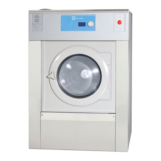
Page 11: Machine Presentation
Machine presentation 3 Machine presentation fig.7749A ① Door Motor Heating unit Drum Detergent container Control panel with Control system I/O modules Drain I/O module type 6 After a repair has been made Whenever a repair has been made, a function check must be performed before the machine can be used again. -
Page 12: Function Check
Function check 4 Function check May only be carried out by qualified personnel. A function check must be made when the installation is finished and before the machine can be ready to be used. Open the manual water valves. Add detergent in the compartment for main wash and start a program. •... -
Page 13: Door And Door Lock
Door and door lock 5 Door and door lock 5.1 Door lock The door lock consists of: • An actuator that locks the door lock and also has one built-in micro switch. The actuator is bi-stable, i.e., it has two stable positions: locked door and unlocked door. The actuator must receive a pulse to lock and unlock the door lock. - Page 14 Door and door lock Replacement of door lock Disconnect the power to the machine. Demount the front panel. ③ fig.7751...
- Page 15 Door and door lock Demount the door. Demount the trim panel. Disconnect the door lock cables and demount the door lock. ④ fig.7753 Mount the new door lock and connect the cables. Mount the trim panel. Mount the door and the front panel.
- Page 16 Door and door lock Emergency opening of door lock The door can be opened by pressing the emergency opening button. To access the emergency opening button, remove the front panel. The emergency opening button can be reached between the left side panel and the trim panel. If not accessible, remove also the trim panel.
-
Page 17: Motor And Motor Control
Motor and motor control 6 Motor and motor control Take care when measuring the motor control system since all components have a potential difference of approximately 300V in relation to protective earth and neutral.The components will contain dangerous voltages when the green LED on the motor control board is on. The motor control system will remain live for 30-60 seconds after cutting the power to the machine and the motor has stopped running. -
Page 18: Replacement Of Motor
Motor and motor control 6.2 Replacement of motor Disconnect the power to the machine. Demount the rear panel. Remove the belt. Demount the cover panel to the motor cable. Disconnect the motor cable and unscrew the earth screw. ⑥ fig.7759... - Page 19 Motor and motor control Demount the motor. ⑦ fig.7760 Mount the new motor. Connect the motor cable and refit the earth screw. Mount the cover panel to the motor cable. Fasten the belt. Make sure the belt is in position. Check the belt tension.
-
Page 20: Heating
Heating 7 Heating 7.1 Replacement of heating element Disconnect the power to the machine. Demount the front panel. Remove the cover to the heating elements. Disconnect the connectors to the heating elements. ⑧ fig.7754A Loosen the bolt to the heating element and gently push on the middle of the heating element to release the flange. -
Page 21: Drum
Drum 8 Drum 8.1 Replacement of drum Disconnect the power to the machine. Demount the back panel. Demount the drain and hoses to the drum. Drain and type of hoses are depending on machine model, (for more information refer to the spare parts list). Demount the air hose and the hose from the detergent compartment on top of the drum. - Page 22 Drum Unscrew the screws to the tension strap. ⑪ fig.7780...
- Page 23 Drum Remove the screws in the on the side panels. Tilt the cabinet backwards a little bit so it is possible to pull out the drum. Carefully pull out the drum. ⑫ fig.7781 Mount the new drum. Fasten the tension strap. Tightening torque 26 Nm. Fasten the screws to the cabinet.
-
Page 24: Replacement Of The Belt
Connect the power to the machine. 8.2.1 Belt tension The belt tension should be according to the table. Model A = Force (N) B = Post tensioning (mm) C = New belt (mm) W565H W575H W5105H W5130H W5180H W5240H W5300H... -
Page 25: Adjusting The Belt Tension
Drum 8.2.2 Adjusting the belt tension 8.2.2.1 W565H, W575H To adjust the belt tension, first undo the motor retaining screw (1) a couple of turns, then press down on the motor to achieve proper tensioning. Lock the locking nut (2) when the tension is correct, then lock the motor retaining screw (1). - Page 26 Drum 8.2.2.2 W5105H, W5130H, W5180H, W5240H, W5300H To adjust the belt tension, first undo the motor retaining screw (1) a couple of turns to increase or decrease the belt tension. • Increase the belt tension by turning the screw (2) clockwise. •...
-
Page 27: Replacing Bearings
Drum 8.3 Replacing bearings Complete tool kit, part No: 472 9913-60 ⑯ fig.7038 1. 432 1723-01: Drift for gaskets (W365/465/565-3105/4105/5105H/N/M/S, W3130/4130/5130N/M/S, EX618/718, 625/725, E/W/SU630/730) 2. 432 1723-02: Drift for gaskets (W3130/4130/5130-3300/4300/5300H, W3180/4180/5180- 3330/4330/5330N/M/S, EX630/730-670/777, E/W/SU640/745-675/777) 3. 432 1716-01: Spacer (W365/465/565-385/485/585H/N/M/S, EX618/718, E/W/SU620/720) 4. -
Page 28: Remove The Pulley
Drum 8.3.1 Remove the pulley Remove the C-clamp from the drum shaft. Mount the puller with puller drags on shaft and pulley. ⑰ fig.7033 Warm the pulley around the shaft so that the aluminium expands slightly. Then it is easier to pull off the pulley. -
Page 29: Demount The Bearing
Drum 8.3.2 Demount the bearing Remove wedge from shaft. Measure the distance (A) between bearing and end of shaft. B = Shaft C = Bearing ⑲ fig.6999 Loosen the bolts in the bearing house. ⑳ fig.7039... - Page 30 Drum Mount two bolts in threaded holes and press until the bearing house is loose. fig.7040 If the front bearing is still on the shaft, use the puller to remove it. In order to be able to put the puller blocks under the bearing, push the rear gable a little. Do not attempt to remove the rear gable when the bearing is still on the shaft.
- Page 31 Drum Alt. 1. Tap the bushing in three places (with about 120° in between). Sometimes it is sufficient to loosen it from the shaft. Alt. 2. Chisel or grind the bushing off the shaft. fig.7044 Tap the bearings from the bearing house. Clean the bearing house thoroughly.
- Page 32 Drum Bearing kit fig.7046 472 9913-12: W365H, W375H/N, W385N/M, W465H, W475H/N, W485N/M, EX618, E/W620 472 9913-13: W3105H/N/M, W3130N/M, W4105H/N/M, W4130N/M, EX625, E/W630 472 9913-15: W3250N/M, W4250N/M, E/W655 472 9913-14: W3180N/M, W4180N/M, E/W640 472 9913-16: W3330N, W4330N, E/W675 472 9913-16: W3330N/M, W4330N/M Tap the bearing gently into the housing with drift and washer.
- Page 33 Drum Turn the housing around and gently tap the rear bearing into the housing using the presser. fig.7049A Mount the sealing rings. A = Bearing housing B = Sealing rings fig.7000...
- Page 34 Drum Put some grease on the inside of the bearing housing. Then it is easier to mount the sealing rings. fig.7051 Fill the first sealing with grease. Place the sealing on the drift with the opening up. Tap carefully it down in the bearing housing. Push it down until it stops.
- Page 35 Drum Mount the third sealing. The lip shall lay against the housing. Don't push too far as the lip can break. Thread the shaft end with M10 and min 20 mm deep. fig.7057 Mount the bearing housing to the rear gable and tighten the bolt crosswise. Note! The marking (up) shall be pointing upwards when rear gable is in place on the machine.
- Page 36 Drum Mount the rear gable over the drum shaft. Be sure to put it on horizontally so that the sealings don't get damaged on the shaft. Mount the adaptor on the shaft end and thread it down to the bottom. fig.7059 Mount presser, washer, nut and puller bolt.
- Page 37 Drum Mount the wedge on the shaft. Mount pulley, sleeve, washer, nut and puller bolt onto the shaft. Thread the bolt to the adaptor on the shaft. Press the pulley onto the shaft. It is easier if the pulley is heated. fig.7061 Lock the pulley with the C-clamp.
-
Page 38: Drain
Drain 9 Drain 9.1 Drain valve The water pressure in the cold water intake is used for closing the drain valve. There is a hose (1) connected between the water intake and the control valve (2). When the control valve is activated it opens and lets water into the supply line (3) which is connected to the drain valve. - Page 39 Drain Replacement of drain valve Disconnect the power to the machine. Demount the front panel. Remove the cover to the heating elements. fig.7751A...
- Page 40 Drain Loosen the hose clamps and demount the hoses (A) from the drain valve. Remove the hose from the valve’s nipple for water supply (B). (Press the orange ring and pull out the hose at the same time). Loosen and unscrew the four retaining nuts of the valve a couple of turns (use a socket, extender and ratchet wrench).
-
Page 41: Detergent Container
Detergent container 10 Detergent container Water connections into the detergent container are fitted with dispensers which mix the detergent thoroughly with water and flush the compartments clean. From the bottom of the detergent container the water is flushed down into the drum. -
Page 42: Replacement Of Detergent Container
Detergent container 10.1 Replacement of detergent container Demount the top panel. Loosen the hose clamps and demount the hoses to the detergent container. Remove the detergent container and mount the new one. Connect the hoses and fasten the hose clamps. fig.7758... -
Page 43: Control Panel
Control panel 11 Control panel 11.1 Control system 11.1.1 Description The control system CPU is electronic and comprises a circuit board containing microprocessor, program memory, serial interface to the motor control, I/O-boards etc. The control system CPU receives its power from a separate power supply unit. fig.7763 The control system receives information about inputs like temperature sensor, level sensor, door status and activates outputs like water valves, drain and heat control. -
Page 44: Connections
Control panel 11.1.2 Connections The control system CPU and I/O module type 10 has the following connections: Board connector Function M-COM Communication, motor control Databus D-BUS D-BUS Databus TACHO Tachometer COIN Coin meter (coin 1, coin 2, blocking) price programming INP 1 Input 1, stop button INP 2... -
Page 45: Replacement Of Control System Cpu
Control panel 11.1.3 Replacement of control system CPU Disconnect the power to the machine. Demount the top panel. Demount the control knob Insert a screwdriver in the upper hole. fig.7491 Gently push the screwdriver inwards and turn the control knob counter-clockwise until the screwdriver goes further in. - Page 46 Control panel Demount the cover ring When the control knob is removed, insert the screwdriver in the lower hole and press gently. Turn the cover ring counter-clockwise until it is possible to remove the cover ring. fig.7490 Demount the control system CPU Demount the cover and disconnect the cables.
- Page 47 Control panel Demount the control knob unit from the control system CPU by unscrewing the screw (A) a bit (4–5 mm) until the control knob unit loosens. Demount the two grounding brackets (B). fig.7640 Demount the I/O module type 10 from the control system CPU by unscrewing the screw (C) a bit (4–5 mm).
- Page 48 Control panel Mount the new control system CPU Start by mounting the control knob unit on the control system CPU. Fasten the screw (A). Mount the I/O module type 10 and fasten the screw (C). Mount the two grounding brackets (B) on the new control system CPU. Mount the control system CPU on the control panel and make sure that the guide pins (D) are in position.
- Page 49 Control panel Mount the control knob on the inner knob. Continue to press with the screwdriver and turn the control knob clockwise until it stops when it is in position. fig.7495A...
-
Page 50: Control Knob
Control panel 11.2 Control knob 11.2.1 Replacement of control knob Disconnect the power to the machine. Insert a screwdriver in the upper hole. fig.7491 Gently push the screwdriver inwards and turn the control knob counter-clockwise until the screwdriver goes further in. fig.7492 Continue turning a quarter of a turn until it is possible to remove the control knob. - Page 51 Control panel Cover ring When the control knob is removed, insert the screwdriver in the lower hole and press gently. Turn the cover ring counter-clockwise until it is possible to remove the cover ring. fig.7490 Mount the new cover ring and rotate it clockwise until it is in position. Rotate the inner knob until the locking device is pointing downwards.
-
Page 52: Usb Connection
Control panel Mount the new control knob on the inner knob. Continue to press with the screwdriver and turn the control knob clockwise until it stops when it is in position. fig.7495A 11.3 USB connection To open the USB connection; use a screwdriver to carefully press and open the lid. fig.W00416... -
Page 53: O Modules
I/O modules 12 I/O modules 12.1 General The machine can be equipped with either two or more I/O modules: • I/O module type 1, 11 or 3 is always installed in the machine at delivery. It controls internal machine functions and outputs to heating, water valves, drain etc. •... -
Page 54: Replacement Of I/O Module
I/O modules 12.2 Replacement of I/O module I/O module type 1, 11 or 3 I/O module type 1, 11 or 3 are installed in the same way. Disconnect the power to the machine. Demount the top panel. Remove the cover on the module. fig.7798 Remove the electrical connections on the module. - Page 55 I/O modules I/O module type 2 Disconnect the power to the machine. Demount the cover panel at the back of the machine. fig.7797 Remove the electrical connections on the module. (Note the position of the connections). Remove the module by lifting it towards you and up a bit and then pushing it to the left. fig.7800 Insert the new module and make sure it is in position.
- Page 56 I/O modules I/O module type 10 Disconnect the power to the machine. Demount the top panel. Remove the cover to the control system and I/O module type 10. Remove the electrical connections on the module. (Note the position of the connections). Loosen the screw (A) a bit and remove the I/O module by lifting it upwards.
- Page 57 I/O module type 6 Disconnect the power to the machine. For W565H, W575H and W5105H: Demount the front panel. For W5130H, W5180H, W5240H and W5300H: Demount the side panel. Disconnect the cable and demount I/O module type 6 by lifting the plastic cover outwards and pulling the I/O module to the right.
-
Page 58: Functions For I/O-Cards
I/O modules 12.3 Functions for I/O-cards The electrical schematic can be one of the following: 12.3.1 External coin meter/Central payment (2A) The signal received from external coin meters must be a pulse between 300–3000 ms (500 ms is recommended) with a minimum pause of 300 ms (500 ms is recommended) between two pulses. fig.6606A... -
Page 59: Central Payment (2B)
I/O modules 12.3.2 Central payment (2B) To start the machine from a central payment system, the payment system must transmit a start pulse to the machine. The start pulse can be either 230V or 24V. In order to receive a feedback signal once the machine has started, 230V or 24V must be connected to connection 19. -
Page 60: Central Payment (2C)
I/O modules 12.3.3 Central payment (2C) The central payment or booking system shall transmit an active (high) signal to the machine once permission has been granted to start the machine. The signal must remain active (high) until the machine starts. A feedback signal will be present on connection 18 and remain active (high) whilst the machine door is closed but the program has not started. -
Page 61: Outputs For Detergent Signals And Inputs For Pause Signals, "Empty" Signal And Price Reduction (2D)
I/O modules 12.3.4 Outputs for detergent signals and inputs for pause signals, "empty" signal and price reduction (2D) The figure shows standard function addressing for machines with the coin program package. By maintaining an active (high) signal on connection 5 ("Price red"), the price of the program can be reduced. -
Page 62: Central Booking/Payment (2F)
I/O modules 12.3.5 Central booking/payment (2F) The central payment or booking system shall provide an active (high) signal to the machine once permission has been granted to start the machine. The signal must remain active (high) until the machine starts. A feedback signal will be present on connection 18 and remain active (high) whilst the program is running. -
Page 63: Machines With I/O Module Type 3
I/O modules 12.3.6 Machines with I/O module type 3 By maintaining an active (high) signal on connection 3 "Price reduction”, the price of the program can be reduced. This function has a number of uses, including providing reductions during a specific period of the day. -
Page 64: Troubleshooting
Troubleshooting 13 Troubleshooting 13.1 General The troubleshooting section is used to trace errors in the machine to a defective component or unit. There is a memory in the control system that will save the selected program for 10 minutes in the case of power failure. -
Page 65: Error Code
Troubleshooting 13.2 Error code An error in the program or in the machine is indicated on the display by an error code and a descriptive text. The error codes are divided into different groups called “Major” comprising different error codes called “Minor”. - Page 66 Troubleshooting Error code Text Major Minor O.H. THERMOSTAT - INLET AIR MAIN DRYER O.H. THERMOSTAT - OUTLET AIR INLET AIR SENSOR OPEN INLET AIR SENSOR SHORT CIRCUITED OUTLET AIR SENSOR OPEN OUTLET AIR SENSOR SHORT CIRCUITED CONDENSE WATER CONTAINER IS FULL HEAT PUMP LOW PRESSURE HEAT PUMP HIGH PRESSURE DRYING ERROR WITH RMC PROGRAM...
- Page 67 Troubleshooting Error code Text Major Minor O.H. DRUM MOTOR DRUM MOTOR NO MOTOR COMMUNINCATION COMMON LOST MOTOR COMMUNICATION Error code Text Major Minor HEATSINK TOO HOT DRUM MOTOR EWD MOTOR TOO HOT NO INTERLOCK NO COMMUNICATION MOTOR SHORT CIRCUIT INTERLOCK HARDWARE LOW DC VOLTAGE HIGH DC VOLTAGE NO PARAMET.
- Page 68 Troubleshooting Error code Text Major Minor OVERVOLTAGE DRUM MOTOR KEB UNDERVOLTAGE PHASE FAILURE OVERCURRENT OVERHEAT INTERNAL NO OVERHEAT INTERNAL OVERHEAT POWER MODULE DRIVE OVERHEAT NO DRIVE OVERHEAT POWER UNIT POWER UNIT NOT READY POWER UNIT INVALID LOAD SHUNT FAULT OVERLOAD NO OVERLOAD OVERLOAD 2 NO OVERLOAD 2...
- Page 69 Troubleshooting Error code Text Major Minor POWER UNIT CHANGED DRUM MOTOR KEB DRIVER RELAY HYBRID COUNTER OVERRUN 1 COUNTER OVERRUN 2 BRAKE INITIALISATION MFC OVER SPEED OVERHEAT INT. NO OVERHEAT POWER MODULE OVERHEAT POWER MODULE EXTERNAL FAULT NO DRIVE OVERHEAT NO OVERHEAT INT.
- Page 70 Troubleshooting Error code Text Major Minor CHARGE CIRCUIT INTERNAL COM. SET SIGNAL, NO TACHO. WAIT 5 MINUTES I/O TYPE 10 ACTUATOR CIRCUIT CHARGE CIRCUIT SET SIGNAL, NO TACHO. WAIT 5 MINUTES ACTUATOR CIRCUIT Error code Text Major Minor INTERNAL ERROR INTERNAL COM.
-
Page 71: Description Of Error Codes And Causes
Troubleshooting 13.3 Description of error codes and causes MAIN COMMON 10:1 INTERNAL ERROR CPU TACHO Tacho input on CPU delivers values that is out of range. Recommended actions: 1. Run motor on highest possible speed in service mode. Check input value for RPM speed. 2. -
Page 72: Main Washer
Troubleshooting MAIN WASHER 11:1 NO WATER This error is shown if the programmed water level is not reached within a certain time, typically 10 minutes. Max. filling time is defined in Config. 1 parameter MAX FILL TIME. This error message can be turned off in Configuration - Error code. Possible causes: Long filling times can be caused by a leaking drain valve, blocked filler valve, defective filler valve, defective valve control board, clogged level sensor hose, leaking level system, etc. - Page 73 Troubleshooting 11:3 DOOR LOCK FAIL This error code will be shown if the control system have not detected the input DOOR LOCKED to be active within a certain time after program start, typically 3 seconds. Possible causes: This can be caused by a mechanical problem preventing door lock to lock, defective door lock, loose cable connection to door lock, broken cables to door lock or mechanical problem with emergency opening of the door.
- Page 74 Troubleshooting 11:5 WATER HIGH TEMP This error code is shown if the temperature around the temperature sensor exceeds + 98°C/208°F Maximum allowed temperature is defined in Config. 2 parameter MAX PROG TEMP. Possible causes: Such high temperature means that the resistance in the sensor is lower than approximately 350 Ω. This can be caused by for example a short circuit in the sensor, break in the cable to the sensor, etc.
- Page 75 Troubleshooting 11:8 NO HEATING This error code is shown if the temperature is increasing too slowly when heating is active. The limit for this error code is normally set to a water temperature increase of approximately 3°C per 10 minutes but can vary depending on the type of machine and software. Minimum temperature increase is defined in Config.
- Page 76 Troubleshooting 11:10 DRUM NOT DRAINED This error code will only occur in drain or extraction modules. Error is activated if the level system has not indicated “empty drum” within a certain time (approximately 3 min). This time may vary depending on the size of the machine. Maximum allowed drain time is defined in Config.
- Page 77 Troubleshooting 11:27 LEVEL OFFSET This error code is shown at program start if the level sensor indicates a level above what the control system CPU can compensate for. If level is indicated a attempt is made to first drain the machine. Maximum allowed level offset is defined in Config.
- Page 78 Troubleshooting 11:29 WATER LEVEL LOW DLCU LEVEL HIGH The DLCU on I/O type 10 contains a mechanical DLCU level switch which ensures that there is no water in the machine when the door unlocks opens. To ensure that the DLCU level switch functions correctly, the DLCU level switch status is compared with the value from the electronic level sensor.
-
Page 79: Main Dryer
Troubleshooting MAIN DRYER 12:1 O.H. THERMOSTAT - INLET AIR This error code is shown if the input O.H. INLET AIR is deactivated. Normally this is due to that protection thermostat for inlet air has trigged due to overheating. The overheating thermostat for inlet air needs to be mechanically restored. When the overheating thermostat for inlet air is restored it is possible to reset the error code from the control system by a short press on the control knob/start button and the ongoing program will continue. - Page 80 Troubleshooting 12:3 INLET AIR SENSOR - OPEN The error code is shown if the analog input INLET AIR TEMP. (PT100) is reading a resistance of more than approximately 185 Ω. Probably caused by broken PT100 sensor or wiring. If the inlet air temperature in the SHOW INPUTS menu show a temperature of 222 °C the inlet air sensor is considered open.
- Page 81 Troubleshooting 12:5 OUTLET AIR SENSOR - OPEN The error code is shown if the analog input OUTLET AIR TEMP (NTC) is reading a resistance of more than approximately 26.7 kΩ. Probably caused by broken NTC sensor or wiring. If the outlet air temperature in the SHOW INPUTS menu shows a temperature of -10 °C the outlet air sensor is open.
- Page 82 Troubleshooting 12:6 OUTLET AIR SENSOR - SHORT-CIRCUITED The error code is shown if the analog input OULET AIR TEMP (NTC) is reading a resistance of less than 330 Ω. Probably caused by broken NTC sensor or damaged wiring. If the outlet air temperature in the SHOW INPUTS menu shows a temperature of 100 °C the outlet air sensor is shorted.
- Page 83 Troubleshooting 12:9 HEAT PUMP LOW PRESSURE This is only a warning message and will not stop the drying process, however, the heat pump will stop. The warning is activated if the input HP LOW PRESSURE (low pressure switch for heat pump) has been deactivated too many times in one drying program.
- Page 84 Troubleshooting 12:11 DRYING ERROR WITH RMC PROGRAM The error code is shown if the analog input RMC does not register the STOP VALUE FOR RMC PROGRAM reached within the maximum drying time (normally 90 minutes). When the error is trigged the machine will automatically go to the cooling module before the program ends. The error code is reset from the control system by a short press on the control knob/start button.
- Page 85 Troubleshooting 12:14 GAS ERROR PRESS GAS RESET BUTTON The error code is shown if input GAS ERROR is activated. This means that no flame has been detected by the gas control box. The metal probe of the flame sensor generates an electrical current when exposed to the burner's flame.
- Page 86 Troubleshooting 12:16 VACUUM SWITCH SHORTED The error code is shown if the input VACUUM was already activated when a program was started. The error code is reset from the control system by a short press on the control knob/start button. A long press on the control knob/start button will make the control system reset and ongoing program will be ended.
-
Page 87: Main Barrier
Troubleshooting 13.3.1 MAIN BARRIER 13:1 DRUM POSITIONING TIMED OUT The error code is shown if input POSITION DRUM 1 and POSITION DRUM 2 is not activated within set time in Config parameter DRUM POS TIMEOUT. Recommended actions: 1. Check inputs from positioning sensors DP1 and DP2. 13:2 DRUM UNLOCKING The error code is shown if input DRUM UNLOCKED is not active or input DRUM LOCKED is still active after 2,5 seconds. -
Page 88: Main W&D
Troubleshooting 13.3.2 MAIN W&D 14:1 EXTRACTION FAILED DRYING ABORTED Only on Wash & Dryer. If extraction is omitted, the drying sequence will also be omitted. -
Page 89: Main Dryer
Troubleshooting 13.3.3 MAIN DRYER 15:2 DOOR OPEN 2 Only on Pocket washer: This error code will be shown if the control system detects that the input DOOR CLOSED 2 (unloading side) has been deactivated during an on-going program. The error can only occur during an on-going program. Possible causes: This can be caused by for example a bad or defective door lock, loose cable to door lock, problem with door lock edge connection, defective input on I/O unit type 10 etc. - Page 90 Troubleshooting 15:17 DOOR LOCK 2 Only on Pocket washer running with one door setup. This error code is activated if the input for DOOR LOCKED 2 is active at program start, i.e. the door is locked although the control system has not requested locking. Possible causes: •...
-
Page 91: Drum Motor Common
Troubleshooting DRUM MOTOR COMMON 20:1 O.H. DRUM MOTOR This error code will be shown if the control system detects that the input OH DRUM MOTOR is deactivated during program run. The overheating protection is automatically restored. When the overheating protection is restored the error code is automatically reset and the ongoing program will continue. -
Page 92: Drum Motor Ewd
Troubleshooting DRUM MOTOR EWD 21:1 HEATSINK TOO HOT This error code is generated by the MCU for drum motor. There is a temperature sensor (NTC) mounted on the MCU cooling flange next to the power transistors in the output stage. If the temperature of the cooling flange gets too high (> 90°C) the error code will be set to protect the transistors. - Page 93 Troubleshooting 21:3 NO INTERLOCK This error code is generated by the MCU for drum motor. The MCU must be powered with 230V / 50 or 60 Hz on the interlock input in order to drive the motor. This signal is a confirmation that the door is closed and locked. MCU receives its commands to rotate the drum from the CPU via a serial communication link between the MCU and CPU.
- Page 94 Troubleshooting 21:5 MOTOR SHORT CIRCIUT This error code is generated by the MCU for drum motor. The MCU reads the power consumption of the motor continuously. If the current for some reason exceeds a predetermined limit, the MCU will cut the current to the motor. After the motor has stopped (= tachometer indicates stationary motor), the MCU will attempt to restart it.
- Page 95 Troubleshooting 21:7 LOW DC VOLTAGE This error code is generated by the MCU for drum motor. The MCU constantly measures the voltage over the mains input. If the voltage is below a predefined limit, the MCU will shut off the current to the motor. Once the motor has stopped (= the tacho sensor indicates that the motor is stationary), the MCU checks to see whether the input voltage is still low.
- Page 96 Troubleshooting 21:12 NO PARAMET. SET IN MCU This error code is generated by the MCU for drum motor. The MCU contains several different parameter sets for different motors. During power up the control system checks that the correct parameter set digit is written into the MCU. If not, the control system will write down the parameter set digit defined in fixed configuration.
-
Page 97: Drum Motor Keb
Troubleshooting 13.3.4 DRUM MOTOR KEB 22:1 OVERVOLTAGE The Motor Control Unit indicates error E.OP. Voltage in DC-link too high. Internal message 1. Recommended actions: 1. Verify input voltage supply to machine (all phases). 2. Check that input choke is connected. 3. - Page 98 Troubleshooting 22:6 OVERHEAT INTERNAL The Motor Control Unit indicates error E.OHI. Internal overheating in frequency controller. Can only be reset when internal temperature has dropped by 3 °C. This is indicated by message E.nOHI. See also error code 22:7. Internal message 6. Recommended actions: 1.
- Page 99 Troubleshooting 22:11 NO DRIVE OVERHEAT The Motor Control Unit indicates error E.ndOH. Error MOTOR OVERHEAT is reset. See also error code 22:9. Internal message 11. Recommended actions: 1. Switch off the main power to machine for 5 minutes. 2. Restart the machine. 22:12 POWER UNIT The Motor Control Unit indicates error E.Pu.
- Page 100 Troubleshooting 22:16 OVERLOAD The Motor Control Unit indicates error E.OL. Overload counter has reached 100%. The error can only be reset after overload counter has reached 0% again. This is indicated by the message E.nOL. See also error 22:17. Internal message 16. Leave machine powered up without running any program for 30 minutes.
- Page 101 Troubleshooting 22:20 NO OVERLOAD 2 The Motor Control Unit indicates error E.nOL2. Cooling time has elapsed, error over load 2 is reset. See also error code 22:19 Internal message 20. 1. Restart the machine. 22:21 EEPROM DEFECTIVE The Motor Control Unit indicates error E.EEP. EEPROM defective.
- Page 102 Troubleshooting 22:31 EXTERNAL FAULT The Motor Control Unit indicates error E.EF. External fault. This error can be triggered if a digital input is programmed as external error input, and trips. Not used in this application. Internal message 31. 22:32 ENCODER 1 The Motor Control Unit indicates error E.EnC.
- Page 103 Troubleshooting 22:49 POWER UNIT CODE INVALID The Motor Control Unit indicates error E.Puci. Power unit code invalid. During initialization the power unit was not recognized or identified as invalid. Internal message 49. Recommended actions: 1. Switch off the main power to machine for 5 minutes. 2.
- Page 104 Troubleshooting 22:55 COUNTER OVERRUN 2 The Motor Control Unit indicates error E.co2. Counter overflow encoder channel 2. Not used in this application Internal message 55. 22:56 BRAKE The Motor Control Unit indicates error E.br. Error brake. Not used in this application. Internal message 56.
- Page 105 Troubleshooting 22:89 OVERHEAT POWER MODULE Warning: The Motor Control Unit indicates A.OH. Overtemperature of power module heatsink. See also error code 22:88. Internal message 89. Recommended actions: 1. Switch off the main power to machine for 30 minutes. 2. Restart the machine. 22:90 EXTERNAL FAULT Warning: The Motor Control Unit indicates A.EF.
- Page 106 Troubleshooting 22:95 PROTECT. ROT. REVERSE The Motor Control Unit indicates error A.Prr. Reverse (left) limit switch is activated. Not used in this application. Internal message 95. 22:96 DRIVE OVERHEAT Warning: The Motor Control Unit indicates A.dOH. Motor temperature too high. Can only be reset when motor temperature has dropped (Resistance at terminals T1/T2 >...
- Page 107 Troubleshooting 22:99 OVERLOAD 1 Warning: The Motor Control Unit indicates A.OL. Overload counter has reached 100%. The warning can only be reset after overload counter has reached 0% again. This is indicated by the message A.nOL. See also message 22:98. Internal message 99.
-
Page 108: Fan Motor Common
Troubleshooting FAN MOTOR COMMON 30:1 O.H. FAN MOTOR This error code will be shown if the control system detects that the input OH FAN MOTOR is deactivated during program run. The overheating protection is automatically restored. When the overheating protection is restored the error code is automatically reset and the ongoing program will continue. -
Page 109: Internal Com
Troubleshooting INTERNAL COM. 40:1–40:10 I/O INTERLOCK Axxx This error code will be shown if the control system detects that the input IO INTERLOCK is not active. I/O unit designation, Axxx, that is shown in the error description is according to electric schematics and electrical component list. - Page 110 Troubleshooting 40:21 I/O COMMUNICATION Only on Barrier washer. The error code is activated if the control system no longer can communicate with Barrier I/O unit or if the communication is intermittent. I/O unit designation that is shown in the error description is according to electric schematics and electrical component list.
-
Page 111: Internal Com. I/O Type 10
Troubleshooting INTERNAL COM. I/O TYPE 10 41:1 CHARGE CIRCUIT The DLCU on I/O board type 10 contains an arming circuit that is charged when the door lock coil is to be activated. For safety reasons, this arming circuit must be discharged when the door lock coil is not to be activated. - Page 112 Troubleshooting 41:3 ACTUATOR CIRCUIT The DLCU on I/O board type 10 continuously controls the circuit to the door lock solenoid. DLCU can detect an open circuit (>50 kΩ) but not a short circuit. If case of an open circuit, CPU will show the error. The error will disappear if the error is removed.
- Page 113 Troubleshooting 41:22 SET SIGNAL NO TACHO. WAIT 5 MINUTES Only on Pocket washer. Pocket washer uses two I/O boards type 10, one for the "Loading side" and one for the "Unloading side". This error relates to I/O board type 10 on "Unloading side". See also corresponding error 41:2 for I/O type 10 on "Loading side".
-
Page 114: Internal Com. I/O Type 6
Troubleshooting INTERNAL COM. I/O TYPE 6 42:1 INTERNAL ERROR I/O unit type 6, reading of internal analog values out of range. Possible causes: • Intermittent error in wiring to I/O type 6 unit. • Internal error in I/O type 6. Recommended actions: 1. -
Page 115: External Com. Cmis
Troubleshooting 13.3.5 EXTERNAL COM. CMIS 50:18 START NOT ALLOWED External MIS system (management information system) has denied the machine to start. MIS system can be any external, communicating system, like CMIS, Payments system, TMIS etc. Recommended actions: 1. Check for reason in payment system. Program not paid, Too short time of booked session left for the selected program, Machine not reserved, Start not allowed. -
Page 116: External Com. Payment
Troubleshooting EXTERNAL COM. PAYMENT 51:22 NO CBT COMMUNICATION Machine connected to payment system using serial communication to machine. Cause: • Communication has been established once and then interupted. Recommended actions: 1. Check electrical connections between CPU and payment system. 2. If running in a network, check network cables between machine and payment system. 3. -
Page 117: External Com. Cmis
Troubleshooting EXTERNAL COM. CMIS 52:1 CMIS COMMUNICATION ERROR Communication between machine and CMIS computer has been interrupted. The warning will be shown at program start for 5 seconds, the next 5 washes. It is then removed automatically. After the warning message has dissapeared the machine will start, but no CMIS data statistics/data will be logged. -
Page 118: Internal
Troubleshooting 13.3.6 INTERNAL 60:5 FATAL ERROR INVALID RUNNING MODE The control system has an internal error during memory read. Recommended actions: 1. Press the control knob/start button to retry. 2. If problem persists, upload new software. 60:11 FATAL ERROR EXTERNAL FLASH WRITE The control system has an internal error during memory read. -
Page 119: Maintenance
Maintenance 14 Maintenance 14.1 Inspect the interior of the machine Inspect the interior of the machine to ensure that no leaks are noticed. During an actual wash cycle; disconnect the power to the machine and proceed as follows: • Remove the top panel, the front and rear panel. •... - Page 120 Electrolux Laundry Systems Sweden AB 341 80 Ljungby, Sweden www.electrolux.com/laundrysystems Share more of our thinking at www.electrolux.com...