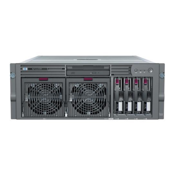
HP ProLiant DL580 Maintenance And Service Manual
Generation 3
Hide thumbs
Also See for ProLiant DL580:
- Setup and installation manual (289 pages) ,
- User manual (139 pages) ,
- Quickspecs (56 pages)

Related Manuals for HP ProLiant DL580


Summary of Contents for HP ProLiant DL580
- Page 1 HP ProLiant DL580 Generation 3 Server Maintenance and Service Guide June 2005 (Third Edition) Part Number 379041-003...
- Page 2 © Copyright 2005 Hewlett-Packard Development Company, L.P. The information contained herein is subject to change without notice. The only warranties for HP products and services are set forth in the express warranty statements accompanying such products and services. Nothing herein should be construed as constituting an additional warranty. HP shall not be liable for technical or editorial errors or omissions contained herein.
-
Page 3: Table Of Contents
Contents Illustrated parts catalog Customer self repair ..........................7 Mechanical components........................8 System components..........................9 Removal and replacement procedures Required tools ............................ 14 Safety considerations ......................... 14 Preventing electrostatic discharge ..................14 Server warnings and cautions ....................15 Preparation procedures........................15 Extending the server from the rack.................. - Page 4 HP ProLiant DL580 Generation 3 Server Maintenance and Service Guide Removing the memory backplane...................... 48 Removing a hard drive blank ......................49 Removing a hot-plug SCSI hard drive ....................50 Removing a hot-plug SAS hard drive ....................51 Removing the SAS-SATA hard drive cage..................52 Removing the SAS-SATA backplane ....................
- Page 5 Contents Processor module LEDs........................97 Rear panel components ........................98 Rear panel LEDs and buttons......................99 Power supply LEDs ......................... 100 System board components ....................... 102 System maintenance switch ....................103 Boot device selector switch ....................104 QuickFind diagnostic display LEDs ..................105 Setting the switch to view port 85 codes ................
-
Page 7: Illustrated Parts Catalog
HP's customer self-repair program offers you the fastest service under either warranty or contract. It enables HP to ship replacement parts directly to you so that you can replace them. Using this program, you can replace parts at your own convenience. -
Page 8: Mechanical Components
HP ProLiant DL580 Generation 3 Server Maintenance and Service Guide Mechanical components Item Description Assembly Spare part Customer part number number self repair Hardware kit, ProLiant DL580 G3 — 385642-001 Server * a) Blank, power supply 366450-002 — b) Blank, CD/DVD/diskette 377569-001 —... -
Page 9: System Components
Latch, PCI, blue (2) * 228194-002 — e) Retainer, card guide, carbon (2) * 379046-001 — f) Retainer, card guide, blue (2) * 379046-002 — Return kit, ProLiant DL580 G3 Server — 378336-001 Tool, Torx, T-15 * 107473-001 199630-001 *Not shown System components... - Page 10 HP ProLiant DL580 Generation 3 Server Maintenance and Service Guide Item Description Assembly Spare part Customer part number self repair number System components Power supply, 910–1300 W 337867-001 364360-001 System cage — — Fan, 120 mm, hot-plug 364517-001 374552-001 Boards...
- Page 11 379980-001 d) Intel® 3.67-GHz Xeon™ 1-MB * 376659-002 389027-001 e) Intel® 3.16-GHz Xeon™ 1-MB * 376659-001 377840-001 Cables Cable kit, data, ProLiant DL580 G3 Server * — 376478-001 a) Cable assembly, USB 346187-001 — b) Cable assembly, power switch 367602-001 —...
- Page 12 HP ProLiant DL580 Generation 3 Server Maintenance and Service Guide Item Description Assembly Spare part Customer part number self repair number Battery-Backed Write Cache battery housing * 338173-001 349989-001 Battery-Backed Write Cache battery * 274779-001 307132-001 Cache board, 128-MB *...
-
Page 13: Removal And Replacement Procedures
Removal and replacement procedures In this section Required tools..........................14 Safety considerations........................14 Preparation procedures .........................15 Removing the front bezel ......................21 Removing a media drive blank .....................23 Removing a media drive.......................23 Removing the processor module ....................24 Removing a processor ........................26 Removing a PPM..........................29 Removing a PCI latch........................30... -
Page 14: Required Tools
HP ProLiant DL580 Generation 3 Server Maintenance and Service Guide Required tools You need the following items for some procedures: • Torx T-15 screwdriver (provided with the server ("Rear panel components" on page 98)) • Phillips screwdriver • Flat-head screwdriver •... -
Page 15: Server Warnings And Cautions
• Extend the server from the rack. If you are performing service procedures in an HP, Compaq branded, telco, or third-party rack cabinet, you can use the locking feature of the rack rails to support the server and gain access to internal components. -
Page 16: Extending The Server From The Rack
HP ProLiant DL580 Generation 3 Server Maintenance and Service Guide For more information about telco rack solutions, refer to the RackSolutions.com website (http://www.racksolutions.com/hp). • Power down the server ("Powering down the server" on page 18). If you must remove a server from a rack or a non-hot-plug component from a server, power down the server. - Page 17 Removal and replacement procedures NOTE: If the server is in a rack and in the shipping configuration, remove the two shipping screws directly behind the levers and the two shipping screws on the rails in the rear of the server. IMPORTANT: If the server is installed in a telco rack, remove the server from the rack to access internal components.
-
Page 18: Powering Down The Server
HP ProLiant DL580 Generation 3 Server Maintenance and Service Guide NOTE: The release latches will lock into place when the rails are fully extended. Powering down the server WARNING: To reduce the risk of personal injury, electric shock, or damage to the equipment, remove the power cord to remove power from the server. -
Page 19: Removing The Server From The Rack
Removal and replacement procedures Removing the server from the rack To remove the server from an HP, Compaq branded, telco, or third-party rack: 1. Power down the server ("Powering down the server" on page 18). 2. Extend the server from the rack. -
Page 20: Removing The System Cage
HP ProLiant DL580 Generation 3 Server Maintenance and Service Guide 3. Lift up on the hood latch, and remove the access panel. 4. After installing hardware options, replace the access panel. Be sure that the panel is securely locked into place before powering up the server. -
Page 21: Removing The Front Bezel
Removal and replacement procedures 8. Remove all power supplies ("Removing a redundant hot-plug power supply" on page 59). 9. Loosen the thumbscrews, and lift the system cage from the server. NOTE: The T-15 Torx screwdriver can be used to loosen the thumbscrews. - Page 22 HP ProLiant DL580 Generation 3 Server Maintenance and Service Guide NOTE: The T-15 Torx screwdriver is shipped with the server and can be located on the rear panel ("Rear panel components" on page 98). 5. Release the two levers on the lower outside corners of the rack.
-
Page 23: Removing A Media Drive Blank
Removal and replacement procedures Removing a media drive blank 1. Power down the server ("Powering down the server" on page 18). 2. Use the T-15 Torx screwdriver to eject the drive blank, and pull the drive blank out of the server. NOTE: The T-15 Torx screwdriver is shipped with the server and can be located on the rear panel ("Rear panel components"... -
Page 24: Removing The Processor Module
HP ProLiant DL580 Generation 3 Server Maintenance and Service Guide NOTE: The T-15 Torx screwdriver is shipped with the server and can be located on the rear panel ("Rear panel components" on page 98). To replace the component, reverse the removal procedure. - Page 25 Removal and replacement procedures 3. Release the latches to unlock the processor module. 4. Lower the processor module lever, and pull the module out of the server.
-
Page 26: Removing A Processor
HP ProLiant DL580 Generation 3 Server Maintenance and Service Guide 5. Release the latch, and open the cover to expose the processors. NOTE: To install a new processor module, remove all processors and PPMs from the processor module. Reinstall the processors and PPMs into the replacement processor module. - Page 27 Removal and replacement procedures 2. Remove the processor module ("Removing the processor module" on page 24). 3. Unlock the processor retaining bracket. 4. Open the processor retaining bracket, and open the processor locking lever. CAUTION: Failure to completely open the processor locking lever prevents the processor from seating during installation, leading to hardware damage.
- Page 28 HP ProLiant DL580 Generation 3 Server Maintenance and Service Guide 6. Install the replacement processor assembly, if applicable. IMPORTANT: Determine the correct processor orientation by observing the guide pins on the base of the processor retaining bracket and the three corresponding guide slots on the processor assembly.
-
Page 29: Removing A Ppm
Removal and replacement procedures 8. Close and lock the processor retaining bracket. 9. Close the cover, and replace the processor module. Removing a PPM The server PPMs provide the proper power to each processor. Each PPM must be installed in the correct slot for the processor. IMPORTANT: Processor socket 1 and PPM slot 1 must be populated at all times or the server will not function properly. -
Page 30: Removing A Pci Latch
HP ProLiant DL580 Generation 3 Server Maintenance and Service Guide 3. Remove the PPM. IMPORTANT: Always install a PPM when you install a processor. The system fails to boot if the corresponding PPM is missing. To replace the component, reverse the removal procedure. -
Page 31: Removing A Pci Retaining Clip
Removal and replacement procedures 7. Remove the PCI latch by pushing up on the clear plastic piece of the PCI latch that extends below the chassis under the latch. To replace the component, reverse the removal procedure. Removing a PCI retaining clip 1. -
Page 32: Removing The Pci-X Hot Plug Basket
HP ProLiant DL580 Generation 3 Server Maintenance and Service Guide 6. Remove the PCI retaining clip. To replace the component, reverse the removal procedure. Removing the PCI-X Hot Plug basket 1. Power down the server ("Powering down the server" on page 18). -
Page 33: Removing A Non-Hot-Plug Expansion Board
Removal and replacement procedures 5. Remove the PCI-X Hot Plug basket ("Removing the PCI-X Hot Plug basket" on page 32). To replace the component, reverse the removal procedure. Removing a non-hot-plug expansion board 1. Power down the server ("Powering down the server" on page 18). 2. -
Page 34: Removing The Pci-X Hot Plug Mezzanine Option
HP ProLiant DL580 Generation 3 Server Maintenance and Service Guide 7. Remove the expansion board. To replace the component, reverse the removal procedure. Removing the PCI-X Hot Plug mezzanine option 1. Power down the server ("Powering down the server" on page 18). -
Page 35: Removing The Pci Express Mezzanine Option
Removal and replacement procedures 8. Loosen the thumbscrews, and lift the mezzanine board from the server. CAUTION: To prevent improper cooling and thermal damage, do not operate the server unless all expansion slots have either an expansion slot cover or an expansion board installed. To replace the component, reverse the removal procedure. -
Page 36: Recovering Data From The Bbwc
HP ProLiant DL580 Generation 3 Server Maintenance and Service Guide 6. Loosen the thumbscrews, and lift the mezzanine board from the server. CAUTION: To prevent improper cooling and thermal damage, do not operate the server unless all expansion slots have either an expansion slot cover or an expansion board installed. -
Page 37: Removing The Bbwc Battery Pack
Removal and replacement procedures 2. Power down the failed server ("Powering down the server" on page 18). If any data is trapped in the cache module, the amber LED on the module ("BBWC LEDs" on page 117) blinks every 15 seconds. CAUTION: Do not detach the cable that connects the battery pack to the cache module. -
Page 38: Removing The Bbwc Cache Module
HP ProLiant DL580 Generation 3 Server Maintenance and Service Guide CAUTION: After the server is powered down, wait 15 seconds and then check the amber LED before unplugging the cable from the cache module. If the amber LED blinks after 15 seconds, do not remove the cable from the cache module. -
Page 39: Removing The System Board
To replace the component, reverse the removal procedure. Removing the system board CAUTION: Only authorized technicians trained by HP should attempt to remove the system board. If you believe the system board requires replacement, contact HP Technical Support before proceeding. - Page 40 HP ProLiant DL580 Generation 3 Server Maintenance and Service Guide IMPORTANT: HP recommends troubleshooting the system using port 85 codes before replacing the system board. Refer to "Troubleshooting the system using port 85 codes (on page 84)" for a list of codes and troubleshooting procedures.
-
Page 41: Re-Entering The Server Serial Number And Product Id
Removal and replacement procedures 16. Using the lever, lift the system board slightly, and slide the system board out through the back of the server. IMPORTANT: If replacing the system board or clearing NVRAM, you must re-enter the server serial number through RBSU ("Re-entering the server serial number and product ID"... -
Page 42: Removing The System Battery
HP ProLiant DL580 Generation 3 Server Maintenance and Service Guide Warning: The serial number should ONLY be modified by qualified service personnel. This value should always match the serial number located on the chassis. 4. Press the Enter key to clear the warning. - Page 43 Removal and replacement procedures 3. Remove the access panel ("Removing the access panel" on page 19). 4. Locate the battery.
-
Page 44: Removing The Media Board
HP ProLiant DL580 Generation 3 Server Maintenance and Service Guide 5. Remove the battery. To replace the component, reverse the removal procedure. Run RBSU to configure the server after replacing the battery. Refer to the HP ROM-Based Setup Utility User Guide on the Documentation CD for more detailed information. -
Page 45: Removing The Scsi Backplane
Removal and replacement procedures 7. Remove the media board. To replace the component, reverse the removal procedure. Removing the SCSI backplane 1. Power down the server ("Powering down the server" on page 18). 2. Remove all media drives ("Removing a media drive" on page 23) and media drive blanks ("Removing a media drive blank"... - Page 46 HP ProLiant DL580 Generation 3 Server Maintenance and Service Guide 8. Record the position of the SCSI simplex/duplex switch.
-
Page 47: Removing The Power Backplane
Removal and replacement procedures 9. Lift the levers, and pull the SCSI backplane out of the server. IMPORTANT: Be sure to set the SCSI simplex/duplex switch to the appropriate setting when replacing the SCSI backplane. To replace the component, reverse the removal procedure. Removing the power backplane 1. -
Page 48: Removing The Memory Backplane
HP ProLiant DL580 Generation 3 Server Maintenance and Service Guide 6. Loosen the thumbscrew, and remove the power backplane from the server. To replace the component, reverse the removal procedure. Removing the memory backplane 1. Power down the server ("Powering down the server" on page 18). -
Page 49: Removing A Hard Drive Blank
Removal and replacement procedures 6. Open the latch, and lift the memory backplane from the server. To replace the component, reverse the removal procedure. Removing a hard drive blank CAUTION: To prevent improper cooling and thermal damage, do not operate the server unless all bays are populated with either a component or a blank. -
Page 50: Removing A Hot-Plug Scsi Hard Drive
HP ProLiant DL580 Generation 3 Server Maintenance and Service Guide Remove the hard drive blank by squeezing the release buttons, and pulling the blank from the server. To replace the component, reverse the removal procedure. Removing a hot-plug SCSI hard drive... -
Page 51: Removing A Hot-Plug Sas Hard Drive
Removal and replacement procedures 3. Remove the hard drive. To replace the component, reverse the removal procedure. Removing a hot-plug SAS hard drive CAUTION: Always power down the server if the boot partition resides on the drive you are replacing or if you are replacing the only drive in the server. -
Page 52: Removing The Sas-Sata Hard Drive Cage
HP ProLiant DL580 Generation 3 Server Maintenance and Service Guide 3. Remove the hard drive. Removing the SAS-SATA hard drive cage 1. Power down the server ("Powering down the server" on page 18). 2. Remove the access panel ("Removing the access panel" on page 19). - Page 53 Removal and replacement procedures 5. Slowly pull the SAS hard drive cage out of the server until there is enough room to reach behind the SAS hard drive cage. 6. Disconnect all cables from the back of the SAS hard drive cage. 7.
- Page 54 HP ProLiant DL580 Generation 3 Server Maintenance and Service Guide CAUTION: When routing cables, always be sure that the cables are not in a position where they can be pinched or crimped. 7. Route the SAS cables through the opening near the SCSI backplane and over the center wall.
- Page 55 Removal and replacement procedures 9. Install the SAS hard drive cage, pulling the slack in the SAS cables over the center wall. 10. Connect the SAS cables to the controller. 11. Secure the SAS hard drive cage with the screws provided in the option kit. 12.
-
Page 56: Removing The Sas-Sata Backplane
HP ProLiant DL580 Generation 3 Server Maintenance and Service Guide The installation is complete. Removing the SAS-SATA backplane 1. Power down the server ("Powering down the server" on page 18). 2. Remove the access panel ("Removing the access panel" on page 19). -
Page 57: Removing A Pci-X Hot Plug Expansion Board
Removal and replacement procedures 7. Remove the SAS backplane from the rear of the cage. To replace the component, reverse the removal procedure. Removing a PCI-X Hot Plug expansion board 1. Extend or remove the server from the rack ("Removing the server from the rack"... -
Page 58: Removing A Power Supply Blank
HP ProLiant DL580 Generation 3 Server Maintenance and Service Guide 5. Lift the latch, and remove the board from the server. CAUTION: To prevent improper cooling and thermal damage, do not operate the server unless all expansion slots have either an expansion slot cover or an expansion board installed. -
Page 59: Removing A Redundant Hot-Plug Power Supply
Removal and replacement procedures 1. Remove the power supply blank. To replace the component, reverse the removal procedure. Removing a redundant hot-plug power supply WARNING: To reduce the risk of electric shock, do not disassemble the power supply or attempt to repair it. Replace it only with the specified spare part. -
Page 60: Replacing Hot-Plug Fans
HP ProLiant DL580 Generation 3 Server Maintenance and Service Guide NOTE: If you remove or replace the primary hot-plug power supply, use the T-15 Torx screwdriver provided with the server to remove the shipping screw. It is located just under the port-colored plastic handle of the power supply unit. - Page 61 Removal and replacement procedures • Remove watches, rings, or other metal objects. • Use tools with insulated handles. • Do not place tools or metal parts on top of batteries. IMPORTANT: Remove and replace one fan at a time. If the system detects two fan failures in the same zone, the server shuts down to avoid thermal damage.
-
Page 62: Memory Overview
HP ProLiant DL580 Generation 3 Server Maintenance and Service Guide Memory overview This server supports up to four memory boards. Each memory board contains four DIMM slots for a total of 16 DIMM slots in the server. Memory can be expanded by installing PC2-3200R Registered DDR2 DRAM DIMMs. - Page 63 Removal and replacement procedures • Always populate the memory boards in sequential order: Board 1, Board 2, Board 3, and Board 4. Any deviation from this requirement results in the server defaulting to Advanced ECC ("Advanced ECC memory" on page 64) on the next reboot.
-
Page 64: Single- And Dual-Rank Dimms
HP ProLiant DL580 Generation 3 Server Maintenance and Service Guide Single- and dual-rank DIMMs PC2-3200 DIMMs can either be single- or dual-rank. While it is not normally important for you to differentiate between these two types of DIMMs, certain DIMM configuration requirements are based on these classifications. - Page 65 Removal and replacement procedures • Board insertions do not convert the AMP mode while the server is running. A server cannot be converted from Advanced ECC to another AMP mode by inserting a board while the server is running. Board insertions in Advanced ECC are solely for making additional memory resources available to the operating system.
-
Page 66: Online Spare Memory
HP ProLiant DL580 Generation 3 Server Maintenance and Service Guide Online spare memory Online spare memory provides a higher level of memory protection than Advanced ECC ("Advanced ECC memory" on page 64). With online spare memory, the probability of a server failing because of uncorrectable memory errors is reduced. -
Page 67: Hot-Plug Mirrored Memory
• Hot-plug operations are not supported. HP recommends the following configurations. These configurations result in optimal use of memory. Other configurations are valid, but do not result in the maximum amount of installed memory being available to the operating system. - Page 68 HP ProLiant DL580 Generation 3 Server Maintenance and Service Guide The following guidelines apply to hot-plug mirrored memory: • All general memory requirements apply ("General memory configuration requirements" on page 62). • Hot-plug mirrored memory is supported with two or four memory boards.
-
Page 69: Hot-Plug Raid Memory
Removal and replacement procedures • Replace only one board at a time. That is, if memory boards 2 and 4 both contain memory errors, remove board 2, correct the error, and replace board 2. Wait for the board status LED to stop flashing before proceeding to board •... -
Page 70: Configuring The Memory
HP ProLiant DL580 Generation 3 Server Maintenance and Service Guide • All general memory requirements apply ("General memory configuration requirements" on page 62). • Hot-plug RAID memory is only supported with four memory boards. • All four memory boards must have the same amount of total memory. - Page 71 Removal and replacement procedures 4. Change POST Speed Up to Disable. 5. Press any key to return to the RBSU main menu. 6. Press the F10 key, when prompted, to exit RBSU. The server reboots and tests all memory in the system. 7.
-
Page 72: Memory Boards And Dimms
HP ProLiant DL580 Generation 3 Server Maintenance and Service Guide IMPORTANT: To reconfigure the memory mode after initial setup, you must reboot the system, enter RBSU, and select the desired AMP mode. Memory boards and DIMMs Memory board and DIMM removal and replacement procedures can be either hot-replace or non-hot-plug, depending on how the server is configured. - Page 73 Removal and replacement procedures Removing a memory board blank To remove the memory board blank, squeeze the levers and pull the blank out of the server. Removing a memory board (non-hot-plug) 1. Power down the server ("Powering down the server" on page 18). 2.
- Page 74 HP ProLiant DL580 Generation 3 Server Maintenance and Service Guide 4. Open the memory board. 5. Replace the DIMM ("Removing DIMMs" on page 76). IMPORTANT: Be sure to observe all DIMM installation requirements for the desired memory mode. 6. Close the memory board.
- Page 75 Removal and replacement procedures 8. Close the ejector lever, and lock the locking switch. 9. Power up the server. 10. Reference the memory board LEDs ("Memory board components and LEDs" on page 94) to be sure that the memory board is functioning properly. Removing a memory board 1.
- Page 76 HP ProLiant DL580 Generation 3 Server Maintenance and Service Guide Removing DIMMs 1. Remove the memory board using the appropriate hot-replace or non-hot-plug procedure ("Removing a memory board (non-hot-plug)" on page 73). 2. Remove the DIMM. To replace the component, reverse the removal procedure.
-
Page 77: Diagnostic Tools
Diagnostic tools In this section SmartStart software ........................77 SmartStart Scripting Toolkit......................78 HP Instant Support Enterprise Edition ..................79 Option ROM Configuration for Arrays ..................79 HP ROM-Based Setup Utility ......................80 ROMPaq utility ..........................80 System Online ROM flash component utility ................81 Integrated Management Log......................81... -
Page 78: Smartstart Scripting Toolkit
Enabling access to the Array Configuration Utility, Array Diagnostic Utility, and Erase Utility SmartStart is included in the HP ProLiant Essentials Foundation Pack. For more information about SmartStart software, refer to the HP ProLiant Essentials Foundation Pack or the HP website (http://www.hp.com/servers/smartstart). -
Page 79: Hp Instant Support Enterprise Edition
(http://www.hp.com/hps/hardware/hw_enterprise.html). To download HP ISEE, visit the HP website (http://www.hp.com/hps/hardware/hw_downloads.html). For installation information, refer to the HP ISEE Client Installation and Upgrade Guide (ftp://ftp.hp.com/pub/services/hardware/info/isee_client.pdf). Option ROM Configuration for Arrays Before installing an operating system, you can use the ORCA utility to create the first logical drive, assign RAID levels, and establish online spare configurations. -
Page 80: Hp Rom-Based Setup Utility
• Configuring memory options • Language selection For more information on RBSU, refer to the HP ROM-Based Setup Utility User Guide on the Documentation CD or the HP website (http://www.hp.com/servers/smartstart). ROMPaq utility Flash ROM enables you to upgrade the firmware (BIOS) with system or option ROMPaq utilities. -
Page 81: System Online Rom Flash Component Utility
Automatically checks for hardware, firmware, and operating system dependencies, and installs only the correct ROM upgrades required by each target server To download the tool and for more information, refer to the HP website (http://h18000.www1.hp.com/support/files/index.html). Integrated Management Log The IML records hundreds of events and stores them in an easy-to-view form. -
Page 82: Integrated Lights-Out Technology
– For Linux: IML Viewer Application • From within HP Insight Diagnostics (on page 83) For more information, refer to the Management CD in the HP ProLiant Essentials Foundation Pack. Integrated Lights-Out technology The iLO subsystem is a standard component of selected ProLiant servers that provides server health and remote server manageability. -
Page 83: Hp Systems Insight Manager
ASR increases server availability by restarting the server within a specified time after a system hang or shutdown. At the same time, the HP SIM console notifies you by sending a message to a designated pager number that ASR has restarted the system. -
Page 84: Usb Support
HP provides support for USB devices before the operating system loads through legacy USB support, which is enabled by default in the system ROM. HP hardware supports USB version 1.1 or 2.0, depending on the version of the hardware. -
Page 85: Processor-Related Port 85 Codes
Diagnostic tools Port 85 code Description Port 85 codes in this format indicate processor-related errors. Refer to "Processor-related port 85 codes (on page 85)" for more information. Port 85 codes in this format indicate memory-related errors. Refer to "Memory- related port 85 codes (on page 86)" for more information. Port 85 codes in this format indicate expansion board-related errors. -
Page 86: Memory-Related Port 85 Codes
HP ProLiant DL580 Generation 3 Server Maintenance and Service Guide 2. Reseat the processor in socket 1. 3. Reseat the remaining processors, rebooting after each installation to identify any failed processors. IMPORTANT: Populate the processors in the following order: 1, 2, 4, 3. -
Page 87: Expansion Board-Related Port 85 Codes
Diagnostic tools – PPMs ("Removing a PPM" on page 29), except the PPM installed in slot – DIMMS ("Removing DIMMs" on page 76), except the first bank from one memory board – Hard drives ("Removing a hot-plug SCSI hard drive" on page 50) –... -
Page 88: Miscellaneous Port 85 Codes
HP ProLiant DL580 Generation 3 Server Maintenance and Service Guide IMPORTANT: Processor socket 1 and PPM slot 1 must be populated at all times or the server will not function properly. – PPMs ("Removing a PPM" on page 29), except the PPM installed in slot –... - Page 89 Diagnostic tools – PPMs ("Removing a PPM" on page 29), except the PPM installed in slot – DIMMS ("Removing DIMMs" on page 76), except the first bank from one memory board – Hard drives ("Removing a hot-plug SCSI hard drive" on page 50) –...
-
Page 91: Server Component Identification
Server component identification In this section Front panel components........................92 Front panel LEDs and buttons ......................93 Memory board components and LEDs ..................94 Processor module LEDs .......................97 Rear panel components.........................98 Rear panel LEDs and buttons .......................99 Power supply LEDs ........................100 System board components ......................102 DIMM slot locations........................108... -
Page 92: Front Panel Components
HP ProLiant DL580 Generation 3 Server Maintenance and Service Guide Front panel components Item Description Memory board or blank USB port Optional multibay drive or blank DVD drive Processor module Hard drive bay... -
Page 93: Front Panel Leds And Buttons
Server component identification Front panel LEDs and buttons Item Description Status UID switch and LED Blue = Activated Flashing blue = Server being managed remotely Off = Deactivated Internal system health Green = Normal (system on) Flashing amber = System health is degraded Flashing red = System health is critical Off = Normal (system off) External system health... -
Page 94: Memory Board Components And Leds
HP ProLiant DL580 Generation 3 Server Maintenance and Service Guide Item Description Status NIC 2 link/activity LED Green = Linked to network Flashing green = Linked with activity on the network Off = No network connection Power on/Standby button Amber = System has AC power and is in standby mode... - Page 95 Server component identification If removal of a single memory board is required and it is the only memory board, power down the server and make the necessary memory changes. Item Description Status Locking switch Release latch Ejector lever Removable Off = Do not remove memory board if server is powered on Green = Memory board can be safely removed...
- Page 96 HP ProLiant DL580 Generation 3 Server Maintenance and Service Guide Item Description Status Spare Off = Board not online or board not configured for Online Spare Memory mode Amber = Correctable error threshold reached; server is in degraded Online Spare Memory mode...
-
Page 97: Processor Module Leds
• If the mode selected is not the desired mode, run RBSU and change the AMP mode. For more information, refer to the section "HP ROM-Based Setup Utility (on page 80)." NOTE: If the Spare, Mirrored, and RAID LEDs are off, the server is in Advanced ECC mode. -
Page 98: Rear Panel Components
HP ProLiant DL580 Generation 3 Server Maintenance and Service Guide PPM LED (1) Processor LED External health Description Amber Flashing red One or more of the following conditions exist: • The processor was replaced and the LEDs will clear after the next reboot •... -
Page 99: Rear Panel Leds And Buttons
Server component identification Item Description Item Description PCI-X non-hot-plug slot 5, 64-bit/133- Serial port PCI-X non-hot-plug slot 4, 64-bit/133- USB ports PCI-X non-hot-plug slot 3, 64-bit/133- Video port Optional PCI-X Hot Plug or optional Keyboard port PCI Express non-hot-plug expansion slot 2 Optional PCI-X Hot Plug or optional Mouse port... -
Page 100: Power Supply Leds
HP ProLiant DL580 Generation 3 Server Maintenance and Service Guide Item Description LED color Status NIC 1 Activity LED Green On or flashing = Network activity Off = No network activity NIC 1 Link LED Green On = Linked to network... - Page 101 Server component identification Fail LED 1 Power LED 2 Description (amber) (green) No AC power to any power supply Flashing Power supply failure (over current) No AC power to this power supply Flashing • AC power present • Standby mode Normal...
-
Page 102: System Board Components
HP ProLiant DL580 Generation 3 Server Maintenance and Service Guide System board components Item Description Item Description Fan 1 PCI-X, non-hot-plug slot 7, 64-bit/100-MHz Fan 2 BBWC battery pack Fan 3 Remote management connector Fan 4 BBWC cache module socket... -
Page 103: System Maintenance Switch
Server component identification Item Description Item Description System maintenance Fan 6 switch System battery Fan 5 Connectors for one of Boot device selector the following: switch (default = FLP TOP) • PCI-X Hot Plug mezzanine option • PCI Express x4 mezzanine option •... -
Page 104: Boot Device Selector Switch
HP ProLiant DL580 Generation 3 Server Maintenance and Service Guide Position Description Function Reserved Reserved Reserved Reserved Password Off = No function protection On = Clears power-on override password and administrator password Invalidate Off = Normal configuration On = Clears NVRAM... -
Page 105: Quickfind Diagnostic Display Leds
QuickFind diagnostic display LEDs The front panel health LEDs indicate only the current hardware status. In some situations, HP SIM might report server status differently than the health LEDs because the software tracks more system attributes. The amber QuickFind diagnostic display LEDs are located on the media board. - Page 106 HP ProLiant DL580 Generation 3 Server Maintenance and Service Guide NOTE: The system management driver must be installed for the internal health LED to provide pre-failure and warranty conditions. Description Fan X One or more of the following conditions exist: •...
-
Page 107: Setting The Switch To View Port 85 Codes
Server component identification Description SCSI BP The SCSI backplane is missing or not properly installed. A memory board is not properly installed. MEM BP A memory backplane is missing or not properly installed. One or more of the following conditions exist: •... -
Page 108: Dimm Slot Locations
HP ProLiant DL580 Generation 3 Server Maintenance and Service Guide DIMM slot locations Item Description Bank DIMM slot 1 DIMM slot 2 DIMM slot 3 DIMM slot 4 SCSI IDs The server supports single- or dual-channel hard drive configurations. The single-channel configuration (simplex mode) supports up to four hard drives on one channel. - Page 109 Server component identification Simplex mode Duplex mode...
-
Page 110: Hot-Plug Scsi Hard Drive Leds
HP ProLiant DL580 Generation 3 Server Maintenance and Service Guide Hot-plug SCSI hard drive LEDs Item LED description Status Activity status On = Drive activity Flashing = High activity on the drive or drive is being configured as part of an array. -
Page 111: Hot-Plug Scsi Hard Drive Led Combinations
Either (1) the drive is part of an array being selected by an array configuration utility; (2) Drive Identification has been selected in HP SIM; or (3) drive firmware is being updated. The drive has failed and has been placed offline. -
Page 112: Sata Or Sas Ids
HP ProLiant DL580 Generation 3 Server Maintenance and Service Guide SATA or SAS IDs NOTE: The server may look different from that shown. When adding SAS hard drives to the server, observe the following general guidelines: • The server supports eight SAS or SATA hot-plug hard drives. -
Page 113: Sata Or Sas Hard Drive Leds
Server component identification SATA or SAS hard drive LEDs Item LED Description Status Fault/UID status Amber = Drive failure Flashing amber = Fault-process activity Blue = Unit identification is active Off = No fault-process activity Online/Activity status Green = Drive activity Flashing green = High activity on the drive or drive is being configured as part of an array... -
Page 114: Fan Locations
HP ProLiant DL580 Generation 3 Server Maintenance and Service Guide Online/Activity Fault/UID LED Interpretation LED (green) (amber/blue) On, off, or Steadily blue The drive is operating normally, and it has been selected by a flashing management application. Amber, flashing A predictive failure alert has been received for this drive. - Page 115 Server component identification • Zone 1 contains four fans (three, plus one redundant) to control the temperature in the processor module area. • Zone 2 contains two fans (one, plus one redundant) to control the temperature in the hard drive bay area. This fan configuration allows the server to continue operating in non-redundant mode if a single fan fails in either zone.
-
Page 116: Hot-Plug Fan Leds
HP ProLiant DL580 Generation 3 Server Maintenance and Service Guide Item Description Zone Fan 2 Fan 3 Fan 4 Fan 5 Fan 6 Hot-plug fan LEDs Status Green = Operating normally Amber = Failed Off = No power... -
Page 117: Bbwc Leds
Server component identification BBWC LEDs Server status LED 1 (amber) LED 2 (green) Battery module status Server is on and has Fast charging normal run time – Flashing The microcontroller is waiting for communication from the host controller. – The battery is fully charged. –... -
Page 119: Server Cabling
Server cabling In this section Storage device cabling guidelines ....................119 PCI-X Hot Plug mezzanine cabling....................119 BBWC cabling..........................120 RILOE II cabling ........................121 Hot-plug SCSI drive cabling ......................121 Hot-plug SAS hard drive cabling ....................123 USB cable assembly ........................123 Power switch cable assembly .....................124 Storage device cabling guidelines CAUTION: To prevent damage to the equipment, be sure that the... -
Page 120: Bbwc Cabling
HP ProLiant DL580 Generation 3 Server Maintenance and Service Guide CAUTION: When routing cables, always be sure that the cables are not in a position where they can be pinched or crimped. BBWC cabling CAUTION: When routing cables, always be sure that the cables are not in a position where they can be pinched or crimped. -
Page 121: Riloe Ii Cabling
Server cabling RILOE II cabling The 30-pin Remote Insight cable ships with the RILOE II cable kit. CAUTION: When routing cables, always be sure that the cables are not in a position where they can be pinched or crimped. IMPORTANT: Install the RILOE II board into slot 7 for ease of cabling. -
Page 122: Scsi Simplex Mode
HP ProLiant DL580 Generation 3 Server Maintenance and Service Guide SCSI simplex mode In the PCI simplex cabling configuration, an optional PCI array controller controls up to four hard drives through one SCSI bus. SCSI duplex mode In the PCI duplex cabling configuration, an optional PCI array controller controls up to four hard drives through two SCSI buses. -
Page 123: Hot-Plug Sas Hard Drive Cabling
Server cabling Hot-plug SAS hard drive cabling CAUTION: When routing cables, always be sure that the cables are not in a position where they can be pinched or crimped. For ease of cabling, route the cables in the server before connecting the cables to the SAS hard drive cage. -
Page 124: Power Switch Cable Assembly
HP ProLiant DL580 Generation 3 Server Maintenance and Service Guide 5. Disconnect all cables from the media board. 6. Remove the media board ("Removing the media board" on page 44). 7. Loosen the screw, and slide the USB cable connector up to remove the cable assembly from the server. - Page 125 Server cabling 9. Remove the power switch cable assembly. To replace the component, reverse the removal procedure.
-
Page 127: Specifications
Specifications In this section Server specifications........................127 Environmental specifications .....................128 Hot-plug power supply calculations ...................128 Server specifications Dimension Specification Height 17.6 cm (6.94 in) Depth 67.3 cm (26.5 in) Width 46.3 cm (19.0 in) Weight (maximum) 47.6 kg (105 lb) Weight (no drives installed) 36.3 kg (80 lb) Input requirement Specification... -
Page 128: Environmental Specifications
(113°F). Altitude maximum for storage corresponds to a pressure minimum of 70 KPa. Hot-plug power supply calculations For hot-plug power supply specifications and calculators to determine electrical and heat loading for the server, refer to the HP Enterprise Configurator website (http://h30099.www3.hp.com/configurator/). -
Page 129: Acronyms And Abbreviations
Acronyms and abbreviations ABEND abnormal end Advanced Memory Protection Automatic Server Recovery BBWC battery-backed write cache backplane Canadian Standards Association double data rate DIMM dual inline memory module... - Page 130 HP ProLiant DL580 Generation 3 Server Maintenance and Service Guide error checking and correcting International Electrotechnical Commission Integrated Lights-Out Integrated Management Log initial program load interrupt request light-emitting diode multi-processor specification NEMA National Electrical Manufacturers Association NFPA National Fire Protection Association...
- Page 131 Acronyms and abbreviations network interface controller NVRAM non-volatile memory ORCA Option ROM Configuration for Arrays peripheral component interface PCI Express peripheral component interconnect express PCI-E peripheral component interconnect express PCI-X peripheral component interconnect extended power distribution unit POST Power-On Self Test Processor Power Module...
- Page 132 HP ProLiant DL580 Generation 3 Server Maintenance and Service Guide ProLiant Support Pack preboot eXecution environment RBSU ROM-Based Setup Utility RILOE II Remote Insight Lights-Out Edition II serial attached SCSI SATA serial ATA SCSI small computer system interface SDRAM synchronous dynamic RAM...
- Page 133 Acronyms and abbreviations support software diskette TMRA recommended ambient operating temperature unit identification universal serial bus Version Control Agent VHDCI very high density cable interconnect...
-
Page 135: Index
CSR (customer self repair) 7 health LEDs 112 customer self repair 7 hot-plug power supply 103 HP Insight Diagnostics 85 HP ProLiant Essentials Foundation Pack 85 HP Systems Insight Manager, overview 85 diagnostic tools 79, 82, 84, 85 diagnostics utility 85 dimensions, server 131... - Page 136 HP ProLiant DL580 Generation 3 Server Maintenance and Service Guide Instant Support Enterprise Edition 81 PCI retaining clip 31 Integrated Lights-Out (iLO) 84 PCI slot release lever 30 PCI slots 100 PCI-X basket 32 PCI-X Hot Plug mezzanine 34, 100...
- Page 137 Index safety considerations 14 SAS backplane 56 SAS hard drive cabling 52 SAS hard drive LEDs 115 SAS-SATA hard drive cage 52 SATA backplane 56 SATA cabling 52 SATA drives 114 scripted installation 80 SCSI backplane 45 SCSI hard drive cabling 124 SCSI hard drive cabling, duplex mode 126 SCSI hard drive cabling, SCSI mode 125 SCSI IDs 110...