Table of Contents
Advertisement
QQ
3 7 63 1515 0
SERVICE MANUAL
Dolby noise reduction manufactured under license from Dolby Labo-
ratories Licensing Corporation.
"DOLBY" and the double-D symbol a are trademarks of Dolby
Laboratories Licensing Corporation.
TE
L 13942296513
CD player section
Signal-to-noise ratio
96 dB
Frequency response
10 - 20,000 Hz
Wow and flutter
Below measurable limit
Cassette player section
Tape track
4-track 2-channel stereo
Wow and flutter
0.08 % (WRMS)
Frequency response
30 - 18,000 Hz
Signal-to-noise ratio
Cassette type
Dolby B NR
TYPE II, IV
67 dB
TYPE I
64 dB
Tuner section
FM
Tuning range
87.5 - 108.0 MHz
Antenna terminal
External antenna connector
Intermediate frequency 10.7 MHz
Usable sensitivity
9 dBf
Selectivity
75 dB at 400 kHz
Signal-to-noise ratio
65 dB (stereo),
68 dB (mono)
Harmonic distortion at 1 kHz
0.7% (stereo),
0.4% (mono)
Separation
35 dB at 1 kHz
Frequency response
30 - 15,000 Hz
www
.
MICROFILM
http://www.xiaoyu163.com
Dolby NR off
58 dB
55 dB
x
ao
u163
y
i
http://www.xiaoyu163.com
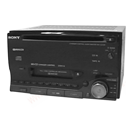
WX-C570R
2 9
8
Model Name Using Similar Mechanism
CD
CD Drive Mechanism Type
Section
Optical Pick-up Name
Model Name Using Similar Mechanism
TC
Section
Tape Transport Mechanism Type
Q Q
3
6 7
1 3
1 5
SPECIFICATIONS
MW/LW
Tuning range
Antenna terminal
Intermediate frequency 10.71 MHz/450 kHz
Sensitivity
Power amplifier section
Outputs
Speaker impedance
Maximum power output 35 W × 4 (at 4 ohms)
CHANGER CONTROL AUDIO MASTER
co
.
– 1 –
9 4
2 8
AEP Model
UK Model
0 5
8
2 9
9 4
2 8
MW : 531 - 1,602 kHz
LW : 153 - 281 kHz
External antenna connector
MW : 30 µV
LW : 50 µV
Speaker outputs
(sure seal connectors)
4 - 8 ohms
– Continued on next page –
m
9 9
CDX-3180
MG-363X-121
KSS-521A
XR-2800
MG-25E-136
9 9
Advertisement
Table of Contents

Related Manuals for Sony WX-C570R


Summary of Contents for Sony WX-C570R
- Page 1 WX-C570R 3 7 63 1515 0 SERVICE MANUAL AEP Model UK Model Dolby noise reduction manufactured under license from Dolby Labo- Model Name Using Similar Mechanism CDX-3180 ratories Licensing Corporation. CD Drive Mechanism Type MG-363X-121 “DOLBY” and the double-D symbol a are trademarks of Dolby...
- Page 2 COMPONENTS IDENTIFIED BY MARK ! OR DOTTED LINE WITH MARK ! ON THE SCHEMATIC DIAGRAMS AND IN THE PARTS LIST ARE CRITICAL TO SAFE OPERATION. REPLACE THESE COMPONENTS WITH SONY PARTS WHOSE PART NUMBERS APPEAR AS SHOWN IN THIS MANUAL OR IN SUPPLEMENTS PUBLISHED BY SONY.
-
Page 3: Table Of Contents
http://www.xiaoyu163.com 3 7 63 1515 0 TABLE OF CONTENTS 1. GENERAL 4. MECHANICAL ADJUSTMENTS ......27 Location of Controls ............... 4 Getting Started ................ 5 5. ELECTRICAL ADJUSTMENTS Setting the Clock ..............5 Tape Section ................. 27 CD Player ................5 Tuner Section ................ -
Page 4: General
http://www.xiaoyu163.com SECTION 1 GENERAL 3 7 63 1515 0 This section extracted from instruction manual. L 13942296513 u163 – 4 – http://www.xiaoyu163.com... - Page 5 http://www.xiaoyu163.com 3 7 63 1515 0 L 13942296513 u163 – 5 – http://www.xiaoyu163.com...
- Page 6 http://www.xiaoyu163.com 3 7 63 1515 0 L 13942296513 u163 – 6 – http://www.xiaoyu163.com...
- Page 7 http://www.xiaoyu163.com 3 7 63 1515 0 L 13942296513 u163 – 7 – http://www.xiaoyu163.com...
- Page 8 http://www.xiaoyu163.com 3 7 63 1515 0 L 13942296513 u163 – 8 – http://www.xiaoyu163.com...
- Page 9 http://www.xiaoyu163.com 3 7 63 1515 0 L 13942296513 u163 – 9 – http://www.xiaoyu163.com...
- Page 10 http://www.xiaoyu163.com 3 7 63 1515 0 L 13942296513 u163 – 10 – http://www.xiaoyu163.com...
- Page 11 http://www.xiaoyu163.com 3 7 63 1515 0 L 13942296513 u163 – 11 – http://www.xiaoyu163.com...
- Page 12 http://www.xiaoyu163.com 3 7 63 1515 0 L 13942296513 u163 – 12 – http://www.xiaoyu163.com...
- Page 13 http://www.xiaoyu163.com 3 7 63 1515 0 L 13942296513 u163 – 13 – http://www.xiaoyu163.com...
- Page 14 http://www.xiaoyu163.com 3 7 63 1515 0 L 13942296513 u163 – 14 – http://www.xiaoyu163.com...
- Page 15 http://www.xiaoyu163.com 3 7 63 1515 0 L 13942296513 u163 – 15 – http://www.xiaoyu163.com...
- Page 16 http://www.xiaoyu163.com 3 7 63 1515 0 L 13942296513 u163 – 16 – http://www.xiaoyu163.com...
-
Page 17: Front Panel Assy
http://www.xiaoyu163.com SECTION 2 DISASSEMBLY 3 7 63 1515 0 Note : Follow the disassembly procedure in the numerical order given. 2-1. FRONT PANEL ASSY 7 cover 5 PTT 2.6x6 6 PTT 2.6x10 4 PTT 2.6x6 3 PTT 2.6x6 9 claws 1 PTT 2.6x14 2 PTT 2.6x6 L 13942296513... -
Page 18: Cd Mechanism Block
http://www.xiaoyu163.com 3 7 63 1515 0 2-3. CD MECHANISM BLOCK 6 bracket (CD) 5 PTT 2.6x6 4 CD mechanism block 1 PTT 2.6x10 2 PTT 2.6x6 3 CN401 L 13942296513 2-4. HEAT SINK 1 PTT 2.6x10 4 heat sink 2 PTT 2.6x10 3 PTT 2.6x10 u163 –... -
Page 19: Cd Board
http://www.xiaoyu163.com 3 7 63 1515 0 2-5. CD BOARD 4 ground point screw (PTT 2.6x6) 3 CN403 2 CN404 5 PTT 2.6x10 7 CD board 1 CN802 6 claw L 13942296513 2-6. TAPE MECHANISM BLOCK 3 PTT 2.6x6 5 tape mechanism block 4 CN321 u163 2 PTT 2.6x6... -
Page 20: Main Board
http://www.xiaoyu163.com 3 7 63 1515 0 2-7. MAIN BOARD 2 MAIN board 1 ground point screws (PTT 2.6x6) 3 insulating sheet L 13942296513 2-8. CHASSIS (T) SUB ASSY 3 P 2x3 2 P 2x3 4 chassis (T) sub assy 1 Unsolder the lead wires. -
Page 21: Lever Assy
http://www.xiaoyu163.com 3 7 63 1515 0 2-9. LEVER ASSY 5 guide (disc) 6 lever (R) assy 3 tension spring (LR) 7 lever (L) assy 1 PS 2x4 2 DISC IN SW board L 13942296513 4 claws 2-10. SERVO BOARD 6 PS 2x4 5 PS 2x4 2 CN2 1 CN3... -
Page 22: Roller Assy
http://www.xiaoyu163.com 3 7 63 1515 0 2-11. ROLLER ASSY • When installing, take note of the positions arm (roller) and washers. (Fig. 1) washer washers washer Fig. 1 3 roller assy 4 PS 2x3 2 arm (roller) 5 LOAD SW board 1 tension spring (RA) L 13942296513 2-12. -
Page 23: Optical Pick-Up Block
http://www.xiaoyu163.com 3 7 63 1515 0 2-13. OPTICAL PICK-UP BLOCK 1 P 2x3 2 sled motor assy 3 optical pick-up block L 13942296513 u163 – 23 – http://www.xiaoyu163.com... -
Page 24: Assembly Of Mechanism Deck
http://www.xiaoyu163.com SECTION 3 ASSEMBLY OF MECHANISM DECK 3 7 63 1515 0 Note : Follow the assembly procedure in the numerical order given. 7 Holder the hanger by bending the claw. HOUSING 5 Fit projection on C part. 1 Install the catcher to the hanger. 2 Install the hanger onto two claws of the housing. -
Page 25: Lever (Ldg-A)/(Ldg-B)
http://www.xiaoyu163.com 3 7 63 1515 0 LEVER (LDG-A) / (LDG-B) shaft A shaft A shaft B shaft C shaft B 1 Fit the lever (LDG-A) on shafts A – C and install it. 3 type-E stop ring 2.0 2 Fit the lever (LDG-B) on shafts A and B and install it. -
Page 26: Guide (C), Guide
http://www.xiaoyu163.com 3 7 63 1515 0 GUIDE (C), GUIDE 3 guide 2 guide (C) 1 three claws L 13942296513 MOUNTING POSITION OF MAIN MOTOR ASSY (M904) 3 belt (25) 2 precision screws +P 2x2 1 main motor assy (capstan/reel) u163 30˚... -
Page 27: Mechanical Adjustments
http://www.xiaoyu163.com SECTION 4 SECTION 5 MECHANICAL ADJUSTMENTS ELECTRICAL ADJUSTMENTS 3 7 63 1515 0 PRECAUTION See the adjustment location from on page 31 for the 1. Wipe the following components with an absorbent cotton cloth adjustment. moistened with alcohol before adjustment : PB head Pinch roller TAPE SECTION... -
Page 28: Tuner Section
http://www.xiaoyu163.com 3 7 63 1515 0 0 dB = 1 µV TUNER SECTION FM Auto Scan/Stop Level Adjustment Setting : D-BASS switch : OFF Cautions during repair TUNER button : FM When the tuner unit is defective, replace it by a new one because its internal block is difficult to repair. - Page 29 http://www.xiaoyu163.com 3 7 63 1515 0 FM Stereo Separation Adjustment FM RDS S-Meter Adjustment Setting : Setting : D-BASS switch : OFF D-BASS switch : OFF TUNER button : FM TUNER button : FM FM RF signal FM RF signal generator generator level meter...
- Page 30 http://www.xiaoyu163.com 3 7 63 1515 0 MW Auto Scan/Stop Level Adjustment Note : This adjustment should be performed after the FM Auto Scan / Stop Level Adjustment is done. Setting : D-BASS switch : OFF TUNER button (twice) : MW 30 Ω...
-
Page 31: Cd Section
http://www.xiaoyu163.com 3 7 6 3 1 5 1 5 0 Focus Gain Adjustment (Coarse adjustment) Adjustment Location : CD SECTION This adjustment is not required unless the following parts are replaced: Note : • Optical pick-up 1. CD Block basically constructed to operate without adjustment. •... -
Page 32: Diagrams
WX-C570R SECTION 6 DIAGRAMS 3 7 6 3 1 5 1 5 0 6-1. BLOCK DIAGRAM — CD SECTION — OPTICAL PICK-UP RF AMP, SERVO CONTROL DIGITAL SIGNAL PROCESSOR D/A CONVERTER KSS-521A IC802 IC801 MAIN 35 PD1 14 RF... -
Page 33: Block Diagram -Tape Section
WX-C570R 3 7 6 3 1 5 1 5 0 6-2. BLOCK DIAGRAM — TAPE SECTION — TAPE L-CH MAIN SECTION TAPE EQ/DOLBY NR SYSTEM CONTROL CD SYSTEM CONTROL FL DRIVE IC301 IC501(2/2) IC401(2/2) IC701 FWD/REV HP901 F ROUT... -
Page 34: Block Diagram -Main Section
WX-C570R 3 7 6 3 1 5 1 5 0 6-3. BLOCK DIAGRAM — MAIN SECTION — TUNER UNIT FM/AM SELECT CN304 ELECTRONIC VOLUME IC303 –2 IC302 R-CH BUS AUDIO IN ANT AM L-CH OUT –1 (ANTENNA) CN803 ANT FM... -
Page 35: Ic Pin Descriptions
AVREF — Reference voltage power supply for D/A conversion. (+5 V) 8 – 15 Not used. UNISI Serial data input (for SONY BUS) UNISO Serial data output (for SONY BUS) UNICKI Serial clock input (for SONY BUS) LINKOFF Link off output Not used. - Page 36 http://www.xiaoyu163.com 3 7 63 1515 0 Pin No. Pin Name Pin Description — (OPEN) — Not used. — AVDD — Power supply for A/D conversion. AVREF — Reference voltage power supply for A/D conversion. 76, 77 Not used. Not used. (Pull up 5 V.) 79, 80 Not used.
- Page 37 System reset output BUS ON Bus ON control output PLL CE PLL chip enable output BUS SI Serial data input (for SONY BUS) BUS SO Serial data output (for SONY BUS) BUS CKI/O Serial clock input/output (for SONY BUS) FLASH W...
- Page 38 http://www.xiaoyu163.com 3 7 63 1515 0 Pin No. Pin Name Pin Description SD IN Signal detector input WIDE WIDE/NARROW select output (Not used in this set.) LED OE LED driver control over write output LED LCK LED driver control serial latch output AM ST AM stereo input (Not used in this set.) FM ST...
- Page 39 http://www.xiaoyu163.com 3 7 63 1515 0 Pin No. Pin Name Pin Description DOL B/C Tape DOLBY B/C select control output (Not used in this set.) FM ON FM ON output TU ON Tuner ON output P-ON System power control output —...
-
Page 40: Circuit Boards Location
http://www.xiaoyu163.com 3 7 63 1515 0 6-5. CIRCUIT BOARDS LOCATION SENSOR board DISC IN SW board LIMIT SW board LOAD SW board SERVO board KEY board SUB board CD board tuner unit (TUX-006/2 (E)) L 13942296513 REEL SENSOR board MAIN board u163 –... - Page 41 http://www.xiaoyu163.com 3 7 6 3 1 5 1 5 0 1 3 9 4 2 2 9 6 5 1 3 w w w u 1 6 3 http://www.xiaoyu163.com...
- Page 42 http://www.xiaoyu163.com 3 7 6 3 1 5 1 5 0 1 3 9 4 2 2 9 6 5 1 3 w w w u 1 6 3 http://www.xiaoyu163.com...
- Page 43 http://www.xiaoyu163.com 3 7 6 3 1 5 1 5 0 1 3 9 4 2 2 9 6 5 1 3 w w w u 1 6 3 http://www.xiaoyu163.com...
- Page 44 http://www.xiaoyu163.com 3 7 6 3 1 5 1 5 0 1 3 9 4 2 2 9 6 5 1 3 w w w u 1 6 3 http://www.xiaoyu163.com...
- Page 45 http://www.xiaoyu163.com 3 7 6 3 1 5 1 5 0 1 3 9 4 2 2 9 6 5 1 3 w w w u 1 6 3 http://www.xiaoyu163.com...
- Page 46 http://www.xiaoyu163.com w w w http://www.xiaoyu163.com...
- Page 47 http://www.xiaoyu163.com w w w http://www.xiaoyu163.com...
- Page 48 http://www.xiaoyu163.com w w w http://www.xiaoyu163.com...
- Page 49 http://www.xiaoyu163.com 3 7 63 1515 0 • IC Block Diagrams IC1 CXD2507AQ (SERVO BOARD) IC801 PCM1717E-ST2 CONTROL CLKO DGND LRCIN ML/MUTE INPUT INTERFACE MODE MC/DM1 SERVO AUTO CONT SEQUENCER DATA BCKIN MD/DM0 XRST DIGITAL FILTER SENS RSTB ZERO SUB CODE MUTE PROCESSOR INTERFACE...
- Page 50 http://www.xiaoyu163.com 3 7 63 1515 0 IC2 CXA1782BQ (SERVO BOARD) 27 26 25 LEVEL S MIRR SENS RF IV AMP1 DFCT C.OUT XRST RF IV AMP2 FE BIAS IIL DATA REGISTER INPUT SHIFT REGISTER DATA ADDRESS DECODER OUTPUT DECODER L 13942296513 TOG1-3 FS1-4 TG1-2...
- Page 51 http://www.xiaoyu163.com 3 7 63 1515 0 IC702 BU2092F-T1 IC51 BU2624FV-E2 XOUT 16 15 14 13 12 11 12 BIT PHASE CONTROL SHIFT CIRCUIT REGISTER REFERENCE OUTPUT DIVIDER 12 BIT BUFFER FMIN MAIN STORAGE (OPEN DRAIN) PRESCALER COUNT REGISTER 5 6 7 8 9 SHIFT REGISTER LATCH AMIN IF COUNT...
- Page 52 http://www.xiaoyu163.com 3 7 63 1515 0 IC301 CXA2510AQ-T4 IC321 LB1638MTP-T1 N.C. 120µ/ 70µ + – MSMODE OUT1 – NR BIAS DRSW PBFB1 MODE PBRIN1 TAPE/AUX TAPESW PBREF1 OUT2 INSW TAPE EQ PBFIN1 NRSW MODE FWD/RVS N.C. PBGND MS ON/ DETECT –...
-
Page 53: Exploded Views
http://www.xiaoyu163.com SECTION 7 EXPLODED VIEWS 3 7 63 1515 0 NOTE: • The mechanical parts with no reference • -XX and -X mean standardized parts, so • Accessories and packing materials and number in the exploded views are not supplied. they may have some difference from the hardware (# mark) list are given in •... -
Page 54: Front Panel Section
Part No. Description Remark 3-021-889-01 PLATE, TRANSPARENT 3-012-505-01 KNOB (D-BASS) 3-021-893-01 SHEET, INDICATION 3-012-484-01 BUTTON (CD EJECT) 3-736-833-11 EMBLEM (NO.3), SONY 3-012-488-01 BUTTON (10 KEY) 3-012-487-11 BUTTON (TUNE) 3-012-503-01 PLATE, LIGHT INTERCEPTION 3-012-486-11 BUTTON (TAPE) 3-021-890-01 BUTTON (PTY) 3-012-485-11 BUTTON (CD) -
Page 55: Chassis Section
http://www.xiaoyu163.com 3 7 63 1515 0 7-3. CHASSIS SECTION MG-25E-136 MG-363X-121 F901 L 13942296513 Ref. No. Part No. Description Remark Ref. No. Part No. Description Remark * 101 X-3373-616-1 CHASSIS ASSY A-3313-812-A CD BOARD, COMPLETE * 102 3-012-514-01 SHEET, INSULATING * 108 3-012-511-01 BRACKET (2F) * 103... -
Page 56: Cd Mechanism Section (1)
http://www.xiaoyu163.com 3 7 63 1515 0 7-4. CD MECHANISM SECTION (1) (MG-363X-121) L 13942296513 M903 Ref. No. Part No. Description Remark Ref. No. Part No. Description Remark * 151 1-659-836-11 DISC IN SW BOARD 3-931-902-03 ARM (ROLLER) * 152 A-3291-816-B CHASSIS (T) SUB ASSY 3-936-756-01 ROLLER (D) 3-931-909-01 SPRING (LR), TENSION 3-321-393-01 WASHER, STOPPER... -
Page 57: Cd Mechanism Section (2)
http://www.xiaoyu163.com 3 7 63 1515 0 7-5. CD MECHANISM SECTION (2) (MG-363X-121) not supplied L 13942296513 Ref. No. Part No. Description Remark Ref. No. Part No. Description Remark 3-931-893-01 ARM, CHUCKING 3-019-805-01 SPRING (KF1), TENSION 3-931-897-01 DAMPER (T) A-3277-802-C CHASSIS (M) ASSY 3-931-879-02 LEVER (D) 3-931-883-01 SPRING (TR), TENSION * 204... -
Page 58: Cd Mechanism Section (3)
http://www.xiaoyu163.com 3 7 63 1515 0 7-6. CD MECHANISM SECTION (3) (MG-363X-121) M901 M902 L 13942296513 The components identified by mark ! or dotted line with mark. ! are critical for safety. Replace only with part number specified. Ref. No. Part No. -
Page 59: Tape Mechanism Section
http://www.xiaoyu163.com 3 7 63 1515 0 7-7. TAPE MECHANISM SECTION (MG-25E-136) HP901 M904 L 13942296513 Ref. No. Part No. Description Remark Ref. No. Part No. Description Remark A-3291-667-A CLUTCH (FR) ASSY 3-933-344-01 GUIDE (C) * 302 3-019-130-01 LEVER (LDG-A) 3-014-798-01 SCREW (HEAD), SPECIAL * 303 3-019-131-01 LEVER (LDG-B) 3-364-151-01 WASHER... -
Page 60: Electrical Parts List
http://www.xiaoyu163.com SECTION 8 ELECTRICAL PARTS LIST 3 7 63 1515 0 NOTE: • Due to standardization, replacements in • Items marked “*” are not stocked since The components identified by mark the parts list may be different from the they are seldom required for routine service. ! or dotted line with mark. - Page 61 http://www.xiaoyu163.com DISC IN SW 3 7 63 1515 0 Ref. No. Part No. Description Remark Ref. No. Part No. Description Remark JC410 1-216-295-00 SHORT R447 1-216-001-00 METAL CHIP 1/10W JC412 1-216-295-00 SHORT R448 1-216-089-00 RES,CHIP 1/10W JC451 1-216-296-00 SHORT R451 1-216-017-00 RES,CHIP 1/10W JC453...
- Page 62 http://www.xiaoyu163.com 3 7 63 1515 0 Ref. No. Part No. Description Remark Ref. No. Part No. Description Remark CN702 1-784-909-11 CONNECTOR, BOARD TO BOARD 16P < TRANSISTOR > < DIODE > Q701 8-729-230-49 TRANSISTOR 2SC2712-YG Q702 8-729-904-48 TRANSISTOR DTB113EK D701 8-719-977-03 DIODE DTZ5.6B Q703 8-729-904-48 TRANSISTOR DTB113EK...
- Page 63 http://www.xiaoyu163.com LIMIT SW LOAD SW MAIN 3 7 63 1515 0 Ref. No. Part No. Description Remark Ref. No. Part No. Description Remark R755 1-208-441-61 RES,CHIP 1.5K 1/10W 1-164-232-11 CERAMIC CHIP 0.01uF R756 1-208-441-61 RES,CHIP 1.5K 1/10W 1-163-037-11 CERAMIC CHIP 0.022uF R757 1-216-659-11 METAL CHIP...
- Page 64 http://www.xiaoyu163.com MAIN 3 7 63 1515 0 Ref. No. Part No. Description Remark Ref. No. Part No. Description Remark C175 1-126-157-11 ELECT 10uF C326 1-124-234-00 ELECT 22uF C176 1-164-492-11 CERAMIC CHIP 0.15uF C351 1-163-809-11 CERAMIC CHIP 0.047uF C177 1-164-492-11 CERAMIC CHIP 0.15uF C352 1-163-809-11 CERAMIC CHIP...
- Page 65 http://www.xiaoyu163.com MAIN 3 7 63 1515 0 Ref. No. Part No. Description Remark Ref. No. Part No. Description Remark C931 1-124-242-00 ELECT 33uF D565 8-719-400-20 DIODE MA152WA C932 1-124-229-00 ELECT 33uF D566 8-719-977-12 DIODE DTZ6.8B C933 1-124-229-00 ELECT 33uF D567 8-719-977-12 DIODE DTZ6.8B C934 1-126-157-11 ELECT...
- Page 66 http://www.xiaoyu163.com MAIN 3 7 63 1515 0 Ref. No. Part No. Description Remark Ref. No. Part No. Description Remark < JUMPER RESISTOR > < RESISTOR > 1-216-295-00 SHORT 1-216-295-00 SHORT 1-216-295-00 SHORT 1-216-049-11 RES,CHIP 1/10W 1-216-037-00 METAL CHIP 1/10W < COIL > 1-216-073-00 METAL CHIP 1/10W 1-216-065-00 RES,CHIP...
- Page 67 http://www.xiaoyu163.com MAIN 3 7 63 1515 0 Ref. No. Part No. Description Remark Ref. No. Part No. Description Remark R187 1-216-081-00 METAL CHIP 1/10W R509 1-216-025-00 RES,CHIP 1/10W R188 1-216-033-00 METAL CHIP 1/10W R510 1-216-025-00 RES,CHIP 1/10W R191 1-216-085-00 METAL CHIP 1/10W R511 1-216-025-00 RES,CHIP...
- Page 68 http://www.xiaoyu163.com MAIN SERVO 3 7 63 1515 0 Ref. No. Part No. Description Remark Ref. No. Part No. Description Remark R583 1-216-675-11 METAL CHIP 0.5% 1/10W A-3309-227-A SERVO BOARD, COMPLETE R584 1-216-675-11 METAL CHIP 0.5% 1/10W ********************** R591 1-216-073-00 METAL CHIP 1/10W R901 1-216-025-00 RES,CHIP...
- Page 69 http://www.xiaoyu163.com SERVO 3 7 63 1515 0 Ref. No. Part No. Description Remark Ref. No. Part No. Description Remark < JUMPER RESISTOR > < TRANSISTOR > 1-216-296-00 SHORT 8-729-904-60 TRANSISTOR DTB113ZK 1-216-296-00 SHORT 8-729-904-86 TRANSISTOR 2SB1197K-Q 1-216-296-00 SHORT 1-216-296-00 SHORT <...
- Page 70 WX-C570R SERVO 3 7 63 1515 0 Ref. No. Part No. Description Remark Ref. No. Part No. Description Remark < VARIABLE RESISTOR > ************** HARDWARE LIST 1-238-091-11 RES, ADJ, CERMET 22K ************** 1-238-091-11 RES, ADJ, CERMET 22K 7-685-792-09 SCREW +PTT 2.6X6 (S) ************************************************************* 7-685-794-09 SCREW +PTT 2.6X10 (S)