
Related Manuals for Dell PowerEdge R220


Summary of Contents for Dell PowerEdge R220
- Page 1 Dell PowerEdge R220 Owner's Manual Regulatory Model: E10S Regulatory Type: E10S003...
- Page 2 WARNING: A WARNING indicates a potential for property damage, personal injury, or death. Copyright © 2015 Dell Inc. All rights reserved. This product is protected by U.S. and international copyright and intellectual property laws. Dell and the Dell logo are trademarks of Dell Inc.
-
Page 3: Table Of Contents
Contents 1 About Your System....................7 ....................7 Front-Panel Features And Indicators .....................9 Back-Panel Features And Indicators ..........................10 NIC Indicator Codes ........................10 Related Documentation ........................ 11 Quick Resource Locator 2 Using The System Setup And Boot Manager..........12 ...................... 13 Choosing The System Boot Mode ........................ - Page 4 ..................35 Removing A 2.5 Inch Hard-Drive Cage ..................36 Installing A 2.5 Inch Hard-Drive Cage .............37 Removing A 2.5 Inch Hard Drive From The Hard-Drive Cage ............37 Installing A 2.5 Inch Hard Drive Into The Hard-Drive Cage ............................38 LED Module ......................
- Page 5 Troubleshooting A Hard Drive ......................71 Troubleshooting Expansion Cards ......................72 Troubleshooting The Processor 5 Using System Diagnostics................. 73 ....................73 Dell Embedded System Diagnostics ..............73 When To Use The Embedded System Diagnostics ................73 Running The Embedded System Diagnostics ......................73 System Diagnostic Controls 6 Jumpers And Connectors.................
- Page 6 ............................. 91 Alert Messages 9 Getting Help......................92 ........................... 92 Contacting Dell ..................... 92 Locating Your System Service Tag ........................92 Documentation Feedback ........................92 Quick Resource Locator...
-
Page 7: About Your System
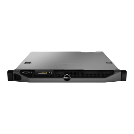
About Your System Front-Panel Features And Indicators Figure 1. Front-Panel Features and Indicators Item Indicator, Button, or Icon Description Connector Power-on indicator, The power-on indicator lights when the system power button power is on. The power button controls the power supply output to the system. - Page 8 Item Indicator, Button, or Icon Description Connector The indicator blinks green to indicate hard-drive Hard-drive indicator activity. Electrical indicator The indicator blinks amber if the system experiences an electrical error (for example, voltage out of range, or a failed power supply or voltage regulator).
-
Page 9: Back-Panel Features And Indicators
Item Indicator, Button, or Icon Description Connector USB connectors (2) Allow you to connect USB devices to the system. The ports are USB 2.0-compliant. System service tag A slide-out label panel that allows you to record system information such as Service Tag, NIC, MAC address, and so on as per your need. -
Page 10: Nic Indicator Codes
Item Indicator, Button, or Icon Description Connector within a rack. When one of these buttons is pressed, the system status indicator on the back flashes until one of the buttons is pressed again. Press to toggle the system ID on and off. If the system stops responding during POST, press and hold the system ID button for more than five seconds to enter BIOS progress mode. -
Page 11: Quick Resource Locator
Use the Quick Resource Locator (QRL) to get immediate access to system information and how-to videos. This can be done by visiting dell.com/QRL or by using your smartphone and a model specific Quick Resource (QR) code located on your Dell PowerEdge system. To try out the QR code, scan the following image. -
Page 12: Using The System Setup And Boot Manager
Enters the System Setup. <F2> Enters System Services, which opens the Dell <F10> Lifecycle Controller 2 (LC2). The Dell LC2 supports systems management features such as operating system deployment, hardware diagnostics, firmware updates, and platform configuration, using a graphical user interface. The exact LC2 feature set is determined by the iDRAC license purchased. -
Page 13: Choosing The System Boot Mode
NOTE: Operating systems must be UEFI-compatible to be installed from the UEFI boot mode. DOS and 32-bit operating systems do not support UEFI and can only be installed from the BIOS boot mode. NOTE: For the latest information on supported operating systems, go to dell.com/ossupport. Entering System Setup Turn on or restart your system. -
Page 14: System Setup Options
Keystroke Action NOTE: For the standard graphics browser only. <Esc> Moves to the previous page till you view the main screen. Pressing <Esc> in the main screen displays a message that prompts you to save any unsaved changes and restarts the system. <F1>... - Page 15 Menu Item Description System Security Displays options to configure the system security settings like, system password, setup password, TPM security, and so on. It also enables or disables the power and NMI buttons on the system. Miscellaneous Displays options to change the system date, time, and so on. Settings System Information Screen Menu Item...
- Page 16 Processor Settings Screen Menu Item Description Logical Processor Allows you to enable or disable logical processors and display the number of logical processors. If the Logical Processor option is set to Enabled, the BIOS displays all the logical processors. If this option is set to Disabled, the BIOS only displays one logical processor per core.
- Page 17 Menu Item Description Port A Auto enables BIOS support for the device attached to SATA port A. By default, Port A is set to Auto. Port B Auto enables BIOS support for the device attached to SATA port B. By default, Port B is set to Auto.
- Page 18 Menu Item Description Embedded NIC1 Allows you to enable or disable the embedded network interface cards 1 and 2. By and NIC2 default, the Integrated Network Card 1 option is set to Enabled. OS Watchdog Allows you to enable or disable the OS watchdog timer. When this field is enabled, Timer the operating system initializes the timer and the OS watchdog timer helps in recovering the operating system.
- Page 19 Menu Item Description Remote Terminal Allows you to set the remote console terminal type. By default, the Remote Type Terminal Type option is set to VT 100/VT 220. Redirection After Allows you to enable or disable to the BIOS console redirection when the Boot operating system is loaded.
- Page 20 Menu Item Description TPM Security Allows you to control the reporting mode of the Trusted Platform Module (TPM). By default, the TPM Security option is set to Off. You can only modify the TPM Status, TPM Activation, TPM Clear, and Intel TXT fields if the TPM Security field is set to either On with Pre-boot Measurements or On without Pre-boot Measurements.
-
Page 21: System And Setup Password Features
Menu Item Description Report Keyboard Allows you to set whether keyboard-related error messages are reported during Errors system boot. By default, the Report Keyboard Errors field is set to Report. F1/F2 Prompt on Allows you to enable or disable the F1/F2 prompt on error. By default, F1/F2 Error Prompt on Error is set to Enabled. - Page 22 • Only lower case letters are valid, upper case letters are not allowed. • Only the following special characters are allowed: space, (”), (+), (,), (-), (.), (/), (;), ([), (\), (]), (`). A message prompts you to re-enter the system password. Re-enter the system password that you entered earlier and click OK.
-
Page 23: Entering The Uefi Boot Manager
Even after you shut down and restart the system, the error message is displayed until the correct password is entered. NOTE: You can use the Password Status option in conjunction with the System Password and Setup Password options to protect your system from unauthorized changes. Operating With A Setup Password Enabled If Setup Password is Enabled, enter the correct setup password before modifying most of the System Setup options. - Page 24 Menu Launch System Enables you to access the System Setup. Setup System Utilities Enables you to run the Dell Diagnostics program, and reboot the system. UEFI Boot Menu Menu Item Description Select UEFI Boot Displays the list of available UEFI boot options (marked with asterisks), select the Option boot option you wish to use and press <Enter>.
-
Page 25: Embedded System Management
NOTE: Accessing some of the features on the iDRAC Settings Utility requires the iDRAC7 Enterprise License upgrade. For more information on using iDRAC, see the iDRAC7 User's Guide at dell.com/esmmanuals. Entering The iDRAC Settings Utility Turn on or restart the managed system. -
Page 26: Installing System Components
Installing System Components Recommended Tools You may need the following items to perform the procedures in this section: • Key to the system keylock • #2 Phillips screwdriver • Wrist grounding strap connected to ground Front Bezel (Optional) Installing The Front Bezel Hook the right end of the bezel onto the chassis. -
Page 27: Opening And Closing The System
Damage due to servicing that is not authorized by Dell is not covered by your warranty. Read and follow the safety instructions that came with the product. -
Page 28: Closing The System
Damage due to servicing that is not authorized by Dell is not covered by your warranty. Read and follow the safety instructions that came with the product. -
Page 29: Chassis Intrusion Switch
Damage due to servicing that is not authorized by Dell is not covered by your warranty. Read and follow the safety instructions that came with the product. -
Page 30: Installing The Chassis Intrusion Switch
Damage due to servicing that is not authorized by Dell is not covered by your warranty. Read and follow the safety instructions that came with the product. -
Page 31: Installing The Optical Drive
Damage due to servicing that is not authorized by Dell is not covered by your warranty. Read and follow the safety instructions that came with the product. -
Page 32: Hard Drives
Damage due to servicing that is not authorized by Dell is not covered by your warranty. Read and follow the safety instructions that came with the product. - Page 33 NOTE: The procedure for removing a 3.5 inch HDD0 and HDD1 cage is identical. If installed, remove the front bezel. Turn off the system and attached peripherals, and disconnect the system from the electrical outlet and from the peripherals. Open the system. Disconnect the power and data cables from the hard drive.
-
Page 34: Installing A 3.5 Inch Hard-Drive Cage
Damage due to servicing that is not authorized by Dell is not covered by your warranty. Read and follow the safety instructions that came with the product. -
Page 35: Installing A 3.5 Inch Hard Drive Into The Hard-Drive Cage
Damage due to servicing that is not authorized by Dell is not covered by your warranty. Read and follow the safety instructions that came with the product. -
Page 36: Installing A 2.5 Inch Hard-Drive Cage
Damage due to servicing that is not authorized by Dell is not covered by your warranty. Read and follow the safety instructions that came with the product. -
Page 37: Removing A 2.5 Inch Hard Drive From The Hard-Drive Cage
Damage due to servicing that is not authorized by Dell is not covered by your warranty. Read and follow the safety instructions that came with the product. -
Page 38: Led Module
Damage due to servicing that is not authorized by Dell is not covered by your warranty. Read and follow the safety instructions that came with the product. -
Page 39: Installing The Led Module
Damage due to servicing that is not authorized by Dell is not covered by your warranty. Read and follow the safety instructions that came with the product. -
Page 40: Installing The Control-Panel Board
Damage due to servicing that is not authorized by Dell is not covered by your warranty. Read and follow the safety instructions that came with the product. -
Page 41: Cooling Fans
Damage due to servicing that is not authorized by Dell is not covered by your warranty. Read and follow the safety instructions that came with the product. -
Page 42: Installing A Cooling Fan
Damage due to servicing that is not authorized by Dell is not covered by your warranty. Read and follow the safety instructions that came with the product. -
Page 43: Cooling Shroud
Damage due to servicing that is not authorized by Dell is not covered by your warranty. Read and follow the safety instructions that came with the product. -
Page 44: Installing The Cooling Shroud
Damage due to servicing that is not authorized by Dell is not covered by your warranty. Read and follow the safety instructions that came with the product. -
Page 45: General Memory Module Installation Guidelines
channel 1: memory sockets 1 and 3 channel 2: memory sockets 2 and 4 The following table shows the memory populations and operating frequencies for the supported configurations. DIMM Type DIMMs Populated/ Operating Frequency (in Maximum DIMM Rank/ Channel MT/s) Channel 1.35 V UDIMM ECC... -
Page 46: Removing Memory Modules
Damage due to servicing that is not authorized by Dell is not covered by your warranty. Read and follow the safety instructions that came with the product. -
Page 47: Installing Memory Modules
Damage due to servicing that is not authorized by Dell is not covered by your warranty. Read and follow the safety instructions that came with the product. -
Page 48: Internal Usb Memory Key (Optional)
Damage due to servicing that is not authorized by Dell is not covered by your warranty. Read and follow the safety instructions that came with the product. -
Page 49: Expansion Cards And Expansion-Card Risers
Figure 20. Removing and Installing the Internal USB Key USB memory key USB memory key connector Expansion Cards And Expansion-Card Risers Expansion Card Installation Guidelines NOTE: To use an expansion card, you need to install an expansion-card riser. If your system configuration does not include the expansion-card riser, purchase a kit with the riser. -
Page 50: Removing An Expansion Card
Damage due to servicing that is not authorized by Dell is not covered by your warranty. Read and follow the safety instructions that came with the product. -
Page 51: Installing An Expansion Card
Damage due to servicing that is not authorized by Dell is not covered by your warranty. Read and follow the safety instructions that came with the product. -
Page 52: Installing The Expansion-Card Riser
Damage due to servicing that is not authorized by Dell is not covered by your warranty. Read and follow the safety instructions that came with the product. -
Page 53: Idrac7 Enterprise Card (Optional)
Damage due to servicing that is not authorized by Dell is not covered by your warranty. Read and follow the safety instructions that came with the product. -
Page 54: Installing The Idrac7 Enterprise Card
Damage due to servicing that is not authorized by Dell is not covered by your warranty. Read and follow the safety instructions that came with the product. -
Page 55: Replacing The System Battery
Damage due to servicing that is not authorized by Dell is not covered by your warranty. Read and follow the safety instructions that came with the product. -
Page 56: Processor
Damage due to servicing that is not authorized by Dell is not covered by your warranty. Read and follow the safety instructions that came with the product. - Page 57 Figure 25. Removing and Installing the Processor Heat Sink retention screws (4) heat sink CAUTION: The processor is held in its socket under strong pressure. Be aware that the release lever can spring up suddenly if not firmly grasped. Position your thumb firmly over the processor socket-release lever and release the lever from the locked position by pushing down and out from under the tab.
-
Page 58: Installing The Processor
Damage due to servicing that is not authorized by Dell is not covered by your warranty. Read and follow the safety instructions that came with the product. -
Page 59: Power Supply Unit
Damage due to servicing that is not authorized by Dell is not covered by your warranty. Read and follow the safety instructions that came with the product. -
Page 60: Installing The Power Supply
Disconnect the power cable from the power supply and remove the straps that bundle and secure the system cables. Open the system. Disconnect all the power cables from the power supply to the system board, hard drives, and optical drive. If applicable, remove the 2.5 inch/3.5 inch hard-drive cage to remove the cables secured by the wire routing latch. -
Page 61: System Board
Damage due to servicing that is not authorized by Dell is not covered by your warranty. Read and follow the safety instructions that came with the product. -
Page 62: Installing The System Board
Damage due to servicing that is not authorized by Dell is not covered by your warranty. Read and follow the safety instructions that came with the product. - Page 63 If applicable, install the front bezel. Reconnect the system to the electrical outlet and turn the system on, including any attached peripherals. 10. Import your new or existing iDRAC Enterprise license. For more information, see the iDRAC7 User's Guide at dell.com/esmmanuals.
-
Page 64: Troubleshooting Your System
Damage due to servicing that is not authorized by Dell is not covered by your warranty. Read and follow the safety instructions that came with the product. -
Page 65: Troubleshooting A Serial I/O Device
Replace the keyboard/mouse with another working keyboard/mouse. If the problem is resolved, replace the faulty keyboard/mouse. If the problem is not resolved, proceed to the next step to begin troubleshooting the other USB devices attached to the system. Power down all attached USB devices and disconnect them from the system. Reboot the system and, if your keyboard is functioning, enter the System Setup. -
Page 66: Troubleshooting A Wet System
Damage due to servicing that is not authorized by Dell is not covered by your warranty. Read and follow the safety instructions that came with the product. -
Page 67: Troubleshooting The System Battery
Damage due to servicing that is not authorized by Dell is not covered by your warranty. Read and follow the safety instructions that came with the product. -
Page 68: Troubleshooting Cooling Problems
Damage due to servicing that is not authorized by Dell is not covered by your warranty. Read and follow the safety instructions that came with the product. -
Page 69: Troubleshooting An Internal Usb Key
Damage due to servicing that is not authorized by Dell is not covered by your warranty. Read and follow the safety instructions that came with the product. -
Page 70: Troubleshooting An Sd Card
Damage due to servicing that is not authorized by Dell is not covered by your warranty. Read and follow the safety instructions that came with the product. -
Page 71: Troubleshooting A Hard Drive
Damage due to servicing that is not authorized by Dell is not covered by your warranty. Read and follow the safety instructions that came with the product. -
Page 72: Troubleshooting The Processor
Damage due to servicing that is not authorized by Dell is not covered by your warranty. Read and follow the safety instructions that came with the product. -
Page 73: Using System Diagnostics
Using System Diagnostics If you experience a problem with your system, run the system diagnostics before contacting Dell for technical assistance. The purpose of running system diagnostics is to test your system hardware without requiring additional equipment or risking data loss. If you are unable to fix the problem yourself, service and support personnel can use the diagnostics results to help you solve the problem. - Page 74 Displays a time-stamped log of the results of all tests run on the system. This is displayed if at least one event description is recorded. For information about embedded system diagnostics, see the ePSA Diagnostics Guide (Notebooks, Desktops and Servers) at dell.com/support/manuals.
-
Page 75: Jumpers And Connectors
Jumpers And Connectors System Board Jumper Settings For information on resetting the password jumper to disable a password, see Disabling A Forgotten Password. Table 3. System Board Jumper Settings Jumper Setting Description PWRD_EN The password feature is enabled (pins 2–4). (default) The password feature is disabled (pins 4–6). -
Page 76: System Board Connectors
System Board Connectors Figure 29. System Board Jumpers and Connectors Item Connector Description POWER CONN Power connector 2, 4, 1 ,3 Memory module sockets INT_USB1 USB connector IO_Riser1 Expansion-card riser connector iDRAC_ENTERPRISE iDRAC7 enterprise card connector NVRAM CLR NVRAM clear jumper CMOS CLR CMOS clear jumper INTRUSION... -
Page 77: Disabling A Forgotten Password
Damage due to servicing that is not authorized by Dell is not covered by your warranty. Read and follow the safety instructions that came with the product. -
Page 78: Technical Specifications
Technical Specifications Processor Processor type Intel Core i3-4130 and Core i3-4330 processorproduct family Intel Pentium processor G3430 and G3420 Intel Celeron processor G1820 Expansion Bus Bus type PCI Express Generation 3 Expansion slots using riser card One half-height, full-length x16 link Memory Architecture 1600 MT/s or 1333 MT/s unbuffered Error... - Page 79 Front Two 4-pin, USB 2.0-compliant Video 15-pin VGA Internal One 4-pin, USB 2.0-compliant Environmental NOTE: For additional information about environmental measurements for specific system configurations, see dell.com/environmental_datasheets. Temperature Maximum 10 °C/h (50 °F/h) Temperature Gradient (Operating and Storage) Storage Temperature –40 °C to 65 °C (–40 °F to 149 °F)
- Page 80 Environmental Six consecutively executed shock pulses in the positive and negative x, y, and z axes (one pulse on each side of the system) of 32 G faired square wave pulse with velocity change at 270 inches/second (686 centimeters/second). Maximum Altitude 3048 m (10,000 Operating Storage...
-
Page 82: System Messages
System Messages System Error Messages System error messages appear on the monitor to notify you of a possible problem with the system. These messages refer to events recorded in the System Event Log (SEL). For information on the SEL and configuring system management settings, see the systems management software documentation. - Page 83 Error Code Message Information ASR0003 Message The watchdog timer power cycled the system. Details The operating system or an application failed to communicate within the time-out period. The system was power-cycled. Action Check the operating system, application, hardware, and system event log for exception events. BAT0002 Message The system board battery has failed.
- Page 84 Error Code Message Information Action Review system logs for power or thermal exceptions. CPU0023 Message CPU <number> is absent. Action Verify processor installation. If present, re-seat the processor. CPU0204 Message CPU <number> <name> voltage is outside of range. Details Voltages outside the allowable range may damage electrical components or may cause the system to shutdown.
- Page 85 Error Code Message Information Details System event log and operating system logs may indicate that the exception is external to the processor. Action Check system and operating system logs for exceptions. If no exceptions are found, continue. Turn off the system and remove input power for one minute.
- Page 86 Error Code Message Information FAN0001 Message Fan <number> RPM is less than the lower critical threshold. Details Fan operating speed is out of range. Action Remove and reinstall the fan. If the issue persists, see Getting Help. HWC1001 Message The <name> is absent. Details The absent device may be necessary for proper operation.
- Page 87 Error Code Message Information MEM0007 Message Unsupported memory configuration; check memory device at location <location>. Details The memory may not be seated correctly, misconfigured, or has failed. Memory size is reduced. Action Check the memory configuration. Re-seat the memory modules. If the issue persists, see Getting Help.
- Page 88 Error Code Message Information PCI1302 Message A bus time-out was detected on a component at bus <bus> device<device> function <func>. Details System performance may be degraded. The device has failed to respond to a transaction. Action Cycle input power, update component drivers, if device is removable, reinstall the device.
- Page 89 Error Code Message Information Action Cycle input power, update component drivers, if device is removable, reinstall the device. PCI1360 Message A bus fatal error was detected on a component at slot <number>. Details System performance may be degraded, or system may fail to operate.
- Page 90 Error Code Message Information SEC0033 Message The chassis is open while the power is off. Details The chassis was opened while the power was off. System security may have been compromised. Action Close the chassis and verify hardware inventory. Check system logs.
-
Page 91: Warning Messages
Error Code Message Information TMP0119 Message The system inlet temperature is less than the lower critical threshold. Details Ambient air temperature is too cool. Action Check the system operating environment. TMP0120 Message The system inlet temperature is greater than the upper warning threshold. -
Page 92: Getting Help
Documentation Feedback If you have feedback for this document, write to documentation_feedback@dell.com. Alternatively, you can click on the Feedback link in any of the Dell documentation pages, fill out the form, and click Submit to send your feedback. Quick Resource Locator Use the Quick Resource Locator (QRL) to get immediate access to system information and how-to videos.