Motorola APX6000XE User Manual
Hide thumbs
Also See for APX6000XE:
- User manual (200 pages) ,
- Quick reference card (2 pages) ,
- Service manual (438 pages)
Table of Contents

Related Manuals for Motorola APX6000XE


Summary of Contents for Motorola APX6000XE
- Page 1 APX™ Two-Way Radios APX6000XE 1) Select/copy image from Photo Library 2) Insert and resize selected image to fill up this white area. 3) Right click on the image, “Order -> Send to Back”. 6000XE Model 1 Interactive End User Toolkit...
-
Page 2: System Requirements
6000XE System Requirements Component Requirement ® ® Computer and processor Intel Pentium II 450MHz or faster processor. Memory 128 megabytes (MB) of RAM or greater. Drive CD-ROM or DVD drive. Display Super VGA (800 × 600) or higher-resolution monitor. ® ®... -
Page 3: Declaration Of Conformity
This declaration is applicable to your radio only if your radio is labeled with the FCC logo shown below. DECLARATION OF CONFORMITY Per FCC CFR 47 Part 2 Section 2.1077(a) Responsible Party Name: Motorola Solutions, Inc. Address: 1303 East Algonquin Road, Schaumburg, IL 60196, U.S.A. Phone Number: 1-800-927-2744 Hereby declares that the product:... - Page 4 6000XE Declaration of Conformity Note: This equipment has been tested and found to comply with the limits for a Class B digital device, pursuant to part 15 of the FCC Rules. These limits are designed to provide reasonable protection against harmful interference in a residential installation.
- Page 5 Conforms to the following regulations: FCC Part 15, Section 15.19, 15.21, and 15.105 Note: Changes or modifications not expressly approved by Motorola may void the users authority, as authorized by the FCC, to operate this device and should not be made. See 47 CFR Part 15.21. Information to the user. The user manual or instruction manual for an intentional or unintentional radiator shall caution the user that changes or modifications not expressly approved by the party responsible for compliance could void the user’s authority to operate the equipment.
- Page 6 6000XE Declaration of Conformity However, there is no guarantee that interference will not occur in a particular installation. If this equipment does cause harmful interference to radio or television reception, which can be determined by turning the equipment off and on, the user is encouraged to try to correct the interference by one or more of the following measures: •...
-
Page 7: Computer Software Copyrights
No duplication or distribution of this document or any portion thereof shall take place without the express written permission of Motorola. No part of this manual may be reproduced, distributed, or transmitted in any form or by any means, electronic or mechanical, for any purpose without the express written permission of Motorola. -
Page 8: Getting Started
6000XE Getting Started This Interactive End User Toolkit (IEUTK) covers the basic operation of the APX™ 6000XE portable radios. However, your dealer or system administrator may have customized your radio for your specific needs. Check with your dealer or system administrator for more information. Notations Used in This Tutorial Throughout the text in this tutorial, you will notice the use of WARNING, Caution, and Note. - Page 9 6000XE HOME Index...
-
Page 10: Radio Parts And Controls
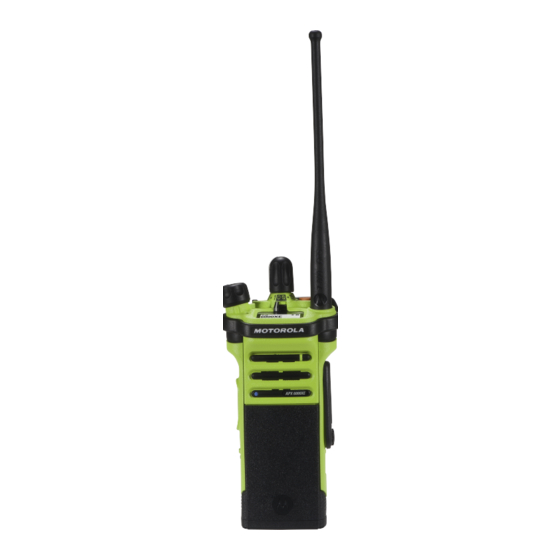
6000XE Radio Parts and Controls Antenna 16-Position On/Off/Volume Select Knob* Control Knob Main Speaker Microphone Bluetooth Pairing Indicator Index... - Page 11 6000XE Radio Parts and Controls 16-Position LED Indicator Select Knob* 3-Position A/B/C Switch Not Programmed Top (Orange) Button Emergency On/Off/Volume Control Knob Top Display 2-Position Concentric Switch Position A = Direct / Talkaround Position B = Blank Index...
- Page 12 6000XE Radio Parts and Controls Microphone Belt Clip Slot Top Side Button Zone Bank Up Push-to-Talk (PTT) Button Battery Side Button 1 Scan Side Button 2 Battery Latch Nuisance Delete Index...
-
Page 13: Fleet Map
6000XE Fleet Map South Band 8CALL90 CH TAC 1 SOUTH BAND FUTURE 1 South FG 8TAC91 TK TAC 2 SOUTH DIR FUTURE 2 EMERGENCY 8TAC92 PV TAC 3 EMERGENCY FUTURE 3 North Band 8TAC93 LS TAC 4 NORTH BAND FUTURE 4 North FG 8TAC94 WR TAC 5... -
Page 14: Preparing Your Radio For Use
• DO NOT discard batteries in a fire. The Motorola-approved battery shipped with your radio is uncharged. Prior to using a new battery, charge it for a minimum of 16 hours to ensure optimum capacity and performance. Note: When charging a battery attached to a radio, turn the radio off to ensure a full charge. -
Page 15: Attaching/Removing The Battery
6000XE Preparing Your Radio for Use Attaching/Removing the Battery With the radio turned off, slide the battery into the radio’s frame until side latches click into place. To remove the battery, turn the radio off. Squeeze the release latches on the bottom of the battery until the battery releases from the radio. -
Page 16: Attaching/Removing The Antenna
6000XE Preparing Your Radio for Use Attaching/Removing the Antenna With the radio turned off, set the antenna in its receptacle and turn clockwise to attach it to the radio. To remove the antenna, turn the antenna counterclockwise. Antenna Make sure you turn off the radio first. Index... - Page 17 6000XE Preparing Your Radio for Use Attaching/Removing the Accessory Connector Cover The accessory connector is located on the antenna side of the radio. It is used to connect accessories to the radio. Note: To prevent damage to the connector, shield it with the connector cover when not in use.
-
Page 18: Attaching/Removing The Belt Clip
6000XE Preparing Your Radio for Use Attaching/Removing the Belt Clip Align the grooves of the belt clip with those of the radio and press upward until you hear a click. To remove the clip, use a flat-bladed object to press the belt clip tab away from the radio. -
Page 19: Turning On/Off The Radio
6000XE Preparing Your Radio for Use Turning On/Off the Radio Rotate the On/Off/Volume Control Knob clockwise until you hear a click. If the power-up test is successful, you see SELFTEST on the radio’s display momentarily, followed by the Home screen. -
Page 20: Adjusting The Volume
6000XE Preparing Your Radio for Use Adjusting the Volume To increase the volume, turn the On/Off/Volume Control Knob clockwise. To decrease the volume, turn this knob counterclockwise. Note: Ensure that the main speaker is pointed towards On/Off/Volume you for increased loudness and intelligibility, especially in Control Knob areas with loud background noises. -
Page 21: Identifying Radio Controls
6000XE Identifying Radio Controls Accessing the Preprogrammed Functions You can access various radio functions through a short or long press of the relevant programmable buttons. 2-Position Concentric Switch 16-Position Position A = Direct / Talkaround Select Knob* Top (Orange) Button 3-Position A/B/C EMERGENCY... -
Page 22: Push-To-Talk (Ptt) Button
6000XE Identifying Radio Controls Push-To-Talk (PTT) Button The PTT button on the side of the radio serves two basic purposes: • While a call is in progress, the PTT button allows the radio to transmit to other radios in the call. Press and hold down PTT button to talk. -
Page 23: Identifying Status Indicators
6000XE Identifying Status Indicators Status Icons The 112 x 32 pixel top monochrome display screen of your radio shows the radio status and operating Power Level conditions. • L = Radio is set at Low power. • H = Radio is set at High power. Battery The number of bars (0 –... -
Page 24: Led Indicator
6000XE Identifying Status Indicators LED Indicator Blinking green – Radio is receiving an individual or The LED indicator shows the operational status of your radio. telephone call, or is on a Priority-Two channel while in the Scan List Programming mode. Solid red –... -
Page 25: Intelligent Lighting Indicators
6000XE Identifying Status Indicators Intelligent Lighting Indicators This feature temporary changes the backlight of the display screen and the keypad, and adds a color bar to the main display screen to help signal that a radio event has occurred. Note: This feature must be preprogrammed by a qualified radio technician. - Page 26 6000XE Identifying Status Indicators Orange Emergency Alerts Critical Alerts Index...
-
Page 27: Alert Tones
6000XE Identifying Status Indicators Alert Tones An alert tone is a sound or group of sounds. Your radio uses alert tones to inform you of your radio’s conditions. The following table lists these tones and when they occur. You Hear Tone Name Heard Short,... - Page 28 6000XE Identifying Status Indicators You Hear Tone Name Heard A Group of Busy When system is busy. Low-Pitched Tones Play Short, Valid Key-Press When a valid key is pressed. Medium-Pitched Radio Self Test Pass When radio passes its power-up self test. Tone Clear Voice At beginning of a non-coded communication.
- Page 29 6000XE Identifying Status Indicators You Hear Tone Name Heard A Group of Fail-soft When the trunking system fails. Medium-Pitched Automatic Call Back When voice channel is available from previous request. Tones Talk Permit (When PTT button is pressed) verifying system accepting transmissions.
-
Page 30: General Radio Operation
6000XE General Radio Operation Selecting a Zone A zone is a group of Talkgroups. Use the following procedure to select a zone. Procedure: 2-Position Concentric 1 To advance to the additional Zones press the Switch* SIDE TOP BUTTON (Purple) 16-Position 2 Press the PTT button to transmit on the displayed zone 3-Position A/B/C... - Page 31 6000XE General Radio Operation Selecting a Radio Talkgroup A Talkgroup is a group of radio characteristics, such as transmit/ receive frequency pairs. Use the following procedure to select a channel. Procedure: 2-Position Concentric Switch* 1 Turn the preprogrammed 16-Position Select knob to the desired Talkgroup.
-
Page 32: Receiving And Responding To A Radio Call
6000XE General Radio Operation Receiving and Responding to a Radio Call Once you have selected the required channel and/or zone, you can proceed to receive and respond to calls. The LED lights up solid red while the radio is transmitting. In conventional mode, the LED lights up solid yellow when the radio is receiving a transmission. -
Page 33: Receiving And Responding To A Talkgroup Call
6000XE General Radio Operation Receiving and Responding to a Radio Call Receiving and Responding to a Talkgroup Call To receive a call from a group of users, your radio must be configured as part of that talkgroup. Procedure: When you receive a talkgroup call (while on the Home screen), depending on how your radio is preprogrammed: 1 ASTRO Conventional Only: The LED lights up solid yellow. -
Page 34: Making A Radio Call
6000XE General Radio Operation Making a Radio Call You can select a zone, talkgroup by using: • The preprogrammed Zone switch • The Talkgroup Selector Knob 2-Position Concentric Switch* 16-Position 3-Position A/B/C Select Knob* Switch* Index... -
Page 35: Advanced Features
6000XE Advanced Features Scan Lists 16-Position Select Knob* Scan lists are created and assigned to individual channels/ groups. Your radio scans for voice activity by On/Off/Volume Antenna Control Knob cycling through the channel/group sequence specified in the scan list for the current Talkgroup. Main Speaker Microphone Bluetooth Pairing Indicator... -
Page 36: Turning Scan On Or Off
6000XE Advanced Features Scan Turning Scan On or Off Procedure: 1 Press the preprogrammed Scan button. The display shows SCAN ON and the scan icon, indicating that scan is enabled. The display shows SCAN OFF, indicating that scan is disabled. SCAN ON Index... -
Page 37: Deleting A Nuisance Channel
6000XE Advanced Features Scan Deleting a Nuisance Channel 16-Position Select Knob* If a channel continually generates unwanted calls or noise (termed a “nuisance” channel), you can temporarily remove the unwanted channel from the scan list. On/Off/Volume This capability does not apply to priority channels or the Control Knob designated transmit channel. -
Page 38: Restoring A Nuisance Channel
6000XE Advanced Features Scan Restoring a Nuisance Channel Procedure: To restore the deleted nuisance channel, do one of the following: • Turn the radio off and then turning it on again. • Stop and restart a scan via the preprogrammed Scan 2-Position Concentric Switch* button or menu. -
Page 39: Emergency Operation
6000XE Advanced Features Emergency Operation The Emergency feature is used to indicate a critical situation. If the Top (Orange) button is preprogrammed to send an emergency signal, this signal overrides any other communication over the selected channel. Your radio supports the following Emergency mode: •... -
Page 40: Sending An Emergency Alarm With Emergency Call
6000XE Advanced Features Emergency Operation Sending an Emergency Alarm with Emergency Call Procedure: 3 Hold the radio vertically 1 to 2 inches (2.5 to 5.0 cm) from your mouth. 1 Press the preprogrammed Emergency button. Press and hold the PTT button. The display shows EMERGNCY and the current zone or Speak clearly into the microphone. -
Page 41: Trunking System Controls
6000XE Advanced Features Trunking System Controls Using the Fail-soft System The fail-soft system ensures continuous radio communications during a trunked system failure. If a trunking system fails completely, the radio goes into fail-soft operation and automatically switches to its fail-soft channel. -
Page 42: Going Out Of Range
6000XE Advanced Features Trunking System Controls Going Out of Range When your radio goes out of the range of the system, it can no longer lock onto a control channel. Procedure: 1 A low-pitched tone sounds. AND/OR The display shows the currently selected zone/channel combination and OUT RNG. -
Page 43: Using The Site Trunking Feature
6000XE Advanced Features Trunking System Controls Using the Site Trunking Feature If the zone controller loses communication with any site, that site reverts to site trunking. The display shows the currently selected zone/channel combination and STE TRNK. Note: When this occurs, you can communicate only with other radios within your trunking site. -
Page 44: Using The Time-Out Timer
6000XE Advanced Features Utilities Using the Time-Out Timer This feature turns off your radio’s transmitter. You cannot Procedure: transmit longer than the preset timer setting. 1 Hold down the PTT button longer than the If you attempt to do so, the radio automatically stops your preprogrammed time.