Table of Contents
Advertisement
Advertisement
Table of Contents

Related Manuals for Asus H170I-PLUS D3


Summary of Contents for Asus H170I-PLUS D3
- Page 1 H170I-PLUS D3...
- Page 2 Product warranty or service will not be extended if: (1) the product is repaired, modified or altered, unless such repair, modification of alteration is authorized in writing by ASUS; or (2) the serial number of the product is defaced or missing.
-
Page 3: Table Of Contents
Contents Safety information ...................... iv About this guide ......................iv Package contents ....................... vi H170I-PLUS D3 specifications summary ..............vi Chapter 1: Product introduction Before you proceed ..................1-1 Motherboard overview ................. 1-1 Central Processing Unit (CPU) ..............1-4 System memory ................... 1-7 Wi-Fi antenna installation ................. -
Page 4: Safety Information
Safety information Electrical safety • To prevent electrical shock hazard, disconnect the power cable from the electrical outlet before relocating the system. • When adding or removing devices to or from the system, ensure that the power cables for the devices are unplugged before the signal cables are connected. If possible, disconnect all power cables from the existing system before you add a device. -
Page 5: Conventions Used In This Guide
Refer to the following sources for additional information and for product and software updates. ASUS websites The ASUS website provides updated information on ASUS hardware and software products. Refer to the ASUS contact information. Optional documentation Your product package may include optional documentation, such as warranty flyers, that may have been added by your dealer. -
Page 6: Package Contents
Extreme Memory Profile (XMP)* * Hyper DIMM support is subject the physical characteristics of individual CPUs. Please refer to the Memory QVL for details. ** Refer to www.asus.com for the Memory QVL (Qualified Vendors List). Integrated Graphics Processor - Intel HD Graphics support Graphics ®... - Page 7 - ASUS Enhanced DRAM Overcurrent Protection - Short circuit damage prevention - ASUS ESD Guards - Enhanced ESD protection - ASUS High-Quality 5K-Hour Solid Capacitors - 2.5x long lifespan with excellent durability - ASUS Stainless Steel Back I/O - 3x more durable corrosion-resistant...
- Page 8 H170I-PLUS D3 specifications summary ASUS special ASUS Exclusive Features features - ASUS USB 3.0 Boost - ASUS AI Suite 3 - ASUS Disk Unlocker - ASUS AI Charger EZ DIY Push Notice - Monitor your PC status with smart devices in real time...
- Page 9 128Mb Flash ROM, UEFI AMI BIOS, PnP, DMI 3.0, WfM2.0, SM BIOS 3.0, BIOS features ACPI 5.1, Multi-language BIOS, ASUS EZ Flash 3, CrashFree BIOS 3, F6 Qfan Control, F3 My Favorites, Quick Note, Last Modified log, F12 PrintScreen, and ASUS DRAM SPD (Serial Presence Detect) memory...
-
Page 11: Chapter 1: Product Introduction
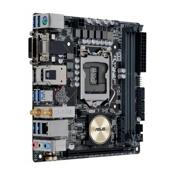
When installing the motherboard, place it into the chassis in the correct orientation. The edge with external ports goes to the rear part of the chassis as indicated in the image. 1.2.2 Screw holes Place four screws into the holes indicated by circles to secure the motherboard to the chassis. Do not overtighten the screws! Doing so can damage the motherboard. ASUS H170I-PLUS D3... -
Page 12: Motherboard Layout
Place this side towards the rear of the chassis 1.2.3 Motherboard layout 17.0cm(6.7in) KBMS_USB3_78 ATX12V CPU_FAN CHA_FAN1 SPDIFO LGA1151 _HDMI 1442K BATT_CON USB3_56 M.2(WIFI) 128Mb BIOS I219V LAN1_USB3_34 Super Intel ® H170 CHA_FAN2 AUDIO1 SB_PWR CLRTC PCIEX16 SPDIF_OUT Chapter 1: Product introduction... -
Page 13: Layout Contents
1-21 7. Intel Z170 Serial ATA 6.0 Gb/s connectors (7-pin SATA6G_3~6, ® 1-15 SATAEXPRESS) 8. USB 2.0 connectors (10-1 pin USB910, USB1112) 1-16 9. USB 3.0 connector (20-1 pin USB3_12) 1-16 10. Standby power LED (SB_PWR) 1-22 11. M.2 Socket 3 1-19 12. Clear RTC RAM (2-pin CLRTC) 1-12 13. Digital audio connector (4-1 pin SPDIF_OUT) 1-21 14. Front panel audio connector (10-1 pin AAFP) 1-18 15. TPM header (14-1 pin TPM) 1-21 16. Serial port connector (10-1 pin COM) 1-18 17. RTC battery header (2-pin BATT_CON) 1-13 ASUS H170I-PLUS D3... -
Page 14: Central Processing Unit (Cpu)
Central Processing Unit (CPU) This motherboard comes with a surface mount LGA1151 socket designed for the 6th Generation Intel Core™ i7 / Core™ i5 / Core™ i3, Pentium and Celeron processors. ® ® ® H170I-PLUS D3 CPU socket LGA1151 Unplug all power cables before installing the CPU. • Ensure that you install the correct CPU designed for the LGA1151 socket only. DO NOT install a CPU designed for LGA1150, LGA1155 and LGA1156 sockets on the LGA1151 socket. • Upon purchase of the motherboard, ensure that the PnP cap is on the socket and the socket contacts are not bent. Contact your retailer immediately if the PnP cap is missing, or if you see any damage to the PnP cap/socket contacts/motherboard components. • Keep the cap after installing the motherboard. ASUS will process Return Merchandise Authorization (RMA) requests only if the motherboard comes with the cap on the LGA1151 socket. • The product warranty does not cover damage to the socket contacts resulting from incorrect CPU installation/removal, or misplacement/loss/incorrect removal of the PnP cap. 1.3.1 Installing the CPU Chapter 1: Product introduction... - Page 15 Top of CPU Bottom of CPU Bottom of CPU Top of CPU ASUS H170I-PLUS D3...
- Page 16 To install the CPU heatsink and fan assembly To uninstall the CPU heatsink and fan assembly Chapter 1: Product introduction...
-
Page 17: System Memory
System memory 1.4.1 Overview This motherboard comes with two Double Data Rate 3 (DDR3) Dual Inline Memory Module (DIMM) sockets. A DDR3 module has the same physical dimensions as a DDR2 DIMM but is notched differently to prevent installation on a DDR2 DIMM socket. DDR3 modules are developed for better performance with less power consumption. The figure illustrates the location of the DDR3 DIMM sockets. According to Intel CPU spec, DIMM voltage below 1.2 V is recommended to protect the ® CPU. Channel Sockets Channel A DIMM_A1 Channel B DIMM_B1 H170I-PLUS D3 240-pin DDR3 DIMM sockets 1.4.2 Memory configurations You may install 1 GB, 2 GB, 4 GB, 8 GB, and 16 GB unbuffered non-ECC DDR3 DIMMs into the DIMM sockets. You can refer to the recommended memory population below. Recommended memory configurations ASUS H170I-PLUS D3... -
Page 18: Installing A Dimm
I nstall a 64-bit Windows OS if you want to install 4GB or more on the ® motherboard. F or more details, refer to the Microsoft support site at http://support.microsoft. ® com/kb/929605/en-us. • The default memory operation frequency is dependent on its Serial Presence Detect (SPD), which is the standard way of accessing information from a memory module. Under the default state, some memory modules for overclocking may operate at a lower frequency than the vendor-marked value. To operate at the vendor-marked or at a higher frequency, refer to section 2.5 Ai Tweaker menu for manual memory frequency adjustment. • Always install the DIMMS with the same CAS Latency. For an optimum compatibility, we recommend that you install memory modules of the same version or data code (D/C) from the same vendor. Check with the vendor to get the correct memory modules. • Visit the ASUS website at www.asus.com for the latest QVL. 1.4.3 Installing a DIMM Chapter 1: Product introduction... - Page 19 To remove a DIMM ASUS H170I-PLUS D3...
-
Page 20: Wi-Fi Antenna Installation
Wi-Fi antenna installation Connect the bundled ASUS 2T2R dual band Wi-Fi antenna connector to the Wi-Fi ports at the back of the chassis. IO Shield • Ensure that the ASUS 2T2R dual band Wi-Fi antenna is securely installed to the Wi-Fi ports. • Ensure that you install the Bluetooth driver before installing the Wi-Fi GO! software. • Ensure that the antenna is at least 20 cm away from all persons. The illustration above is for reference only. The I/O port layout may vary with models, but the Wi-Fi antenna installation procedure is the same for all models. 1-10 Chapter 1: Product introduction... -
Page 21: Expansion Slots
Remove the system unit cover (if your motherboard is already installed in a chassis). Remove the bracket opposite the slot that you intend to use. Keep the screw for later use. Align the card connector with the slot and press firmly until the card is completely seated on the slot. Secure the card to the chassis with the screw you removed earlier. Replace the system cover. 1.6.2 Configuring an expansion card After installing the expansion card, configure it by adjusting the software settings. Turn on the system and change the necessary BIOS settings, if any. See Chapter 2 for information on BIOS setup. Assign an IRQ to the card. Install the software drivers for the expansion card. When using PCI cards on shared slots, ensure that the drivers support “Share IRQ” or that the cards do not need IRQ assignments. Otherwise, conflicts will arise between the two PCI groups, making the system unstable and the card inoperable. 1.6.3 PCI Express 3.0/2.0 x16 slot This motherboard has a PCI Express 3.0/2.0 x16 slot that supports PCI Express 3.0/2.0 x16 graphic cards complying with the PCI Express specifications. ASUS H170I-PLUS D3 1-11... -
Page 22: Headers
– – Intel Shared – – – Headers Clear RTC RAM (2-pin CLRTC) This header allows you to clear the Real Time Clock (RTC) RAM in CMOS. You can clear the CMOS memory of date, time, and system setup parameters by erasing the CMOS RTC RAM data. The onboard button cell battery powers the RAM data in CMOS, which include system setup information such as system passwords. H170I-PLUS D3 Clear RTC RAM To erase the RTC RAM: Turn OFF the computer and unplug the power cord. Use a metal object such as a screwdriver to short the two pins. Plug the power cord and turn ON the computer. Hold down the <Del> key during the boot process and enter BIOS setup to re- enter data. • If the steps above do not help, remove the onboard battery and short the two pins again to clear the CMOS RTC RAM data. After clearing the CMOS, reinstall the battery. • You do not need to clear the RTC when the system hangs due to overclocking. For system failure due to overclocking, use the CPU Parameter Recall (C.P.R.) feature. -
Page 23: Connectors
RTC Battery header (2-pin BATT_CON) This connector is for the lithium CMOS battery. BATT_CON VBAT PIN 1 H170I-PLUS D3 RTC battery header Connectors 1.8.1 Rear panel connectors PS/2 Mouse/Keyboard combo port. This port connects to a PS/2 mouse or PS/2 keyboard. Video Graphics Adapter (VGA) port. This 15-pin port is for a VGA monitor or other VGA-compatible devices. Optical S/PDIF Out port. This port connects an external audio output device via an optical S/PDIF cable. LAN (RJ-45) port. These ports allow Gigabit connection to a Local Area Network (LAN) through a network hub. - Page 24 – – – Side Speaker Out To configure a 7.1-channel audio output: Use a chassis with HD audio module in the front panel to support a 7.1-channel audio output. USB 3.0 ports. These 9-pin Universal Serial Bus (USB) ports are for USB 3.0 devices. • USB 3.0 devices can only be used for data storage. • We strongly recommend that you connect USB 3.0 devices to USB 3.0 ports for faster and better performance from your USB 3.0 devices. • Due to the design of the Intel 100 series chipset, all USB devices connected to the ® USB 2.0 and USB 3.0 ports are controlled by the xHCI controller. Some legacy USB devices must update their firmware for better compatibility. ASUS Wi-Fi GO! These WLAN cards allow your computer to connect to a wireless network. For details, refer to the section 1.5 Wi-Fi antenna installation. 1-14 Chapter 1: Product introduction...
-
Page 25: Internal Connectors
® H170 chipset. SATA6G_3 SATA6G_4 SATA6G_5 RSATA_TXP1 RSATA_TXN1 RSATA_RXN1 RSATA_RXP1 SATA6G_6 RSATA_TXP2 RSATA_TXN2 RSATA_RXN2 RSATA_RXP2 H170I-PLUS D3 Intel SATA 6.0Gb/s connectors ® • These connectors are set to [AHCI] by default. If you intend to create a Serial ATA RAID set using these connectors, set the SATA Mode item in the BIOS to [RAID]. Refer to section 2.6.3 PCH Storage Configuration for details. • Before creating a RAID set, refer to the manual bundled in the motherboard support DVD. • The SATA EXPRESS connector can support one SATA Express device or two SATA devices. ASUS H170I-PLUS D3 1-15... - Page 26 PIN 1 USB3+5V USB3+5V IntA_P1_SSRX- IntA_P2_SSRX- IntA_P1_SSRX+ IntA_P2_SSRX+ IntA_P1_SSTX- IntA_P2_SSTX- IntA_P1_SSTX+ IntA_P2_SSTX+ IntA_P1_D- IntA_P2_D- IntA_P1_D+ IntA_P2_D+ H170I-PLUS D3 USB3.0 connector • The USB 3.0 module is purchased separately. • These connectors are based on xHCI specification. We recommend you to install the related driver to fully use the USB 3.0 ports under Windows ® USB 2.0 connectors (10-1 pin USB910, USB1112) These connectors are for USB 2.0 ports. Connect the USB module cable to these connectors, then install the module to a slot opening at the back of the system chassis. These USB connectors comply with USB 2.0 specification that supports up to 480 Mbps connection speed. USB1112 USB_P11+ USB_P12+...
- Page 27 PWM, go to Advanced Mode > Monitor > Chassis Fan 1/2 Q-Fan Control items in BIOS. Speaker connector (4- pin SPEAKER) This 4-pin connector is for the chassis-mounted system warning speaker. The speaker allows you to hear system beeps and warnings. SPEAKER Speaker Out PIN 1 H170I-PLUS D3 Speaker Out connector ASUS H170I-PLUS D3 1-17...
- Page 28 MICPWR PORT1 L AGND AGND MIC2 PIN 1 PIN 1 HD-audio-compliant Legacy AC’97 pin definition compliant definition H170I-PLUS D3 Front panel audio connector • We recommend that you connect a high-definition front panel audio module to this connector to avail of the motherboard’s high-definition audio capability. • If you want to connect a high-definition or an AC’97 front panel audio module to this connector, set the Front Panel Type item in the BIOS setup to [HD Audio] or [AC97]. Serial port connector (10-1 pin COM) This connector is for a serial (COM) port. Connect the serial port module cable to this connector, then install the module to a slot opening at the back of the system chassis. PIN 1 H170I-PLUS D3 Serial port connector The COM module is purchased separately.
- Page 29 M.2 socket 3 This socket allows you to install an M.2 (NGFF) SSD module. M.2(SOCKET3) H170I-PLUS D3 M.2(SOCKET3) To install a 2242 M.2 SSD module: Align the bigger hole on the mounting kit with the 2260 standoff and secure it with a screw. Install the 2242 M.2 SSD module to the M.2 socket. Secure the M.2 SSD module to the M.2 socket with a screw. • This socket supports M Key and 2242/2260/2280 storage devices. • For a 2242 storage device, use the bundled 2242 mounting kit. • Before installing a 2242 M.2 SSD module, ensure that the mounting kit is properly installed with the bigger screw hole on the 2260 standoff.
- Page 30 +5 Volts Power OK -5 Volts PIN 1 +5 Volts +5 Volts PSON# +3 Volts -12 Volts +3 Volts +3 Volts H170I-PLUS D3 ATX power connectors • For a fully configured system, we recommend that you use a power supply unit (PSU) that complies with ATX 12 V Specification 2.0 (or later version) and provides a minimum power of 350 W. • DO NOT forget to connect the 4-pin/8-pin ATX +12V power plug. Otherwise, the system will not boot up. • We recommend that you use a PSU with higher power output when configuring a system with more power-consuming devices or when you intend to install additional devices. The system may become unstable or may not boot up if the power is...
-
Page 31: System Panel Connector
H170I-PLUS D3 TPM connector The TPM module is purchased separately. System panel connector (10-1 pin F_PANEL) This connector supports several chassis-mounted functions. F_PANEL (NC) HWRST# Ground PWR_LED- HDD_LED- PWR_LED+ HDD_LED+ PIN 1 H170I-PLUS D3 System panel connector • System power LED (2-pin +PWR_LED-) This 2-pin connector is for the system power LED. Connect the chassis power LED cable to this connector. The system power LED lights up when you turn on the system power, and blinks when the system is in sleep mode. • Hard disk drive activity LED (2-pin +HDD_LED-) This 2-pin connector is for the HDD Activity LED. Connect the HDD Activity LED cable to this connector. The HDD LED lights up or flashes when data is read from or written to the HDD. • ATX power button/soft-off button (2-pin PWR_BTN) This connector is for the system power button. Pressing the power switch for more than four seconds while the system is ON turns the system OFF. -
Page 32: Onboard Leds
Onboard LEDs Standby Power LED The motherboard comes with a standby power LED that lights up to indicate that the system is ON, in sleep mode, or in soft-off mode. This is a reminder that you should shut down the system and unplug the power cable before removing or plugging in any motherboard component. The illustration below shows the location of the onboard LED. SB_PWR Standby Power Powered Off H170I-PLUS D3 Standby power LED 1-22 Chapter 1: Product introduction... -
Page 33: Software Support
To run the Support DVD Place the Support DVD into the optical drive. If Autorun is enabled in your computer, the DVD automatically displays the lists of the unique features of your ASUS motherboard. Click the Driver, Utilities, Manual, or Special tabs to display their respective menus. The following screen is for reference only. Click an icon to display a tab Click to install Tick an item and click Install to install it If Autorun is NOT enabled in your computer, browse the contents of the Support DVD to locate the file Setup.exe in the root folder. Double-click the Setup.exe to run the DVD. ASUS H170I-PLUS D3 1-23... - Page 34 1-24 Chapter 1: Product introduction...
-
Page 35: Chapter 2: Bios Information
Managing and updating your BIOS Save a copy of the original motherboard BIOS file to a USB flash disk in case you need to restore the BIOS in the future. Copy the original motherboard BIOS using the ASUS Update utility. -
Page 36: Asus Ez Flash
2.1.2 ASUS EZ Flash 3 The ASUS EZ Flash 3 feature allows you to update the BIOS without using an OS‑based utility. • Ensure that you load the BIOS default settings to ensure system compatibility and stability. Select the Load Optimized Defaults item under the Exit menu. See section 2.10 Exit Menu for details. -
Page 37: Asus Crashfree Bios 3 Utility
2.1.3 ASUS CrashFree BIOS 3 utility The ASUS CrashFree BIOS 3 is an auto recovery tool that allows you to restore the BIOS file when it fails or gets corrupted during the updating process. You can restore a corrupted BIOS file using the motherboard support DVD or a USB flash drive that contains the updated BIOS file. - Page 38 ENTER to select boot device ESC to boot using defaults P2: ST3808110AS (76319MB) aigo miniking (250MB) UEFI: (FAT) ASUS DRW-2014L1T(4458MB) P1: ASUS DRW-2014L1T(4458MB) UEFI: (FAT) aigo miniking (250MB) Enter Setup When the booting message appears, press <Enter> within five (5) seconds to enter FreeDOS prompt.
- Page 39 DO NOT shut down or reset the system while updating the BIOS to prevent system boot failaure. Ensure to load the BIOS default settings to ensure system compatibility and stability. Select the Load Optimized Defaults item under the Exit BIOS menu. See section 2.10 Exit Menu for details. ASUS H170I-PLUS D3 2‑5...
-
Page 40: Bios Setup Program
The BIOS setup screens shown in this section are for reference purposes only, and may not exactly match what you see on your screen. • Visit the ASUS website at www.asus.com to download the latest BIOS file for this motherboard. •... - Page 41 Click the button to manually menus tune the fans Shows the Selects the boot bootable devices Loads optimized device priority default settings The boot device options vary depending on the devices you installed to the system. ASUS H170I-PLUS D3 2‑7...
-
Page 42: Advanced Mode
Advanced Mode The Advanced Mode provides advanced options for experienced end‑users to configure the BIOS settings. The figure below shows an example of the Advanced Mode. Refer to the following sections for the detailed configurations. To access the EZ Mode, click EzMode(F7) or press <F7>. Q-Fan control EZ Tuning Wizard... -
Page 43: Menu Bar
This button above the menu bar allows you to view and tweak the overclocking settings of your system. It also allows you to change the motherboard’s SATA mode from AHCI to RAID mode. Refer to section 2.2.4 EZ Tuning Wizard for more information. ASUS H170I-PLUS D3... -
Page 44: Hot Keys
Search on FAQ Move your mouse over this button to show a QR code. Scan this QR code with your mobile device to connect to the ASUS BIOS FAQ web page. You can also scan the QR code below. Quick Note (F9) This button above the menu bar allows you to key in notes of the activities that you have done in BIOS. -
Page 45: Qfan Control
CPU and chassis fans. Click to select a fan to be configured Select a profile to apply Click to apply to your fans the fan setting Click to undo Click to the changes go back to main menu ASUS H170I-PLUS D3 2-11... -
Page 46: Configuring Fans Manually
Configuring fans manually Select Manual from the list of profiles to manually configure your fans’ operating speed. Speed points Click to manually configure your fans To configure your fans: Select the fan that you want to configure and to view its current status. Click and drag the speed points to adjust the fans’... -
Page 47: Ez Tuning Wizard
2.2.4 EZ Tuning Wizard EZ Tuning Wizard allows you to easily set your SATA HDD/SSD to RAID mode. ASUS H170I-PLUS D3 2‑13... -
Page 48: My Favorites
My Favorites MyFavorites is your personal space where you can easily save and access your favorite BIOS items. 2-14 Chapter 2: Getting started... -
Page 49: Adding Items To My Favorites
• Configuration items such as Memory SPD Information, system time and date. Click Exit (ESC) or press <esc> key to close Setup Tree Map screen. Go to My Favorites menu to view the saved BIOS items. ASUS H170I-PLUS D3 2‑15... -
Page 50: Main Menu
Main menu The Main menu screen appears when you enter the Advanced Mode of the BIOS Setup program. The Main menu provides you an overview of the basic system information, and allows you to set the system date, time, language, and security settings. 2.4.1 Language [English] Allows you to choose the BIOS language version from the options. -
Page 51: User Password
To clear the user password, follow the same steps as in changing a user password, but press <Enter> when prompted to create/confirm the password. After you clear the password, the User Password item on top of the screen shows Not Installed. ASUS H170I-PLUS D3 2‑17... -
Page 52: Ai Tweaker Menu
Ai Tweaker menu The Ai Tweaker menu items allow you to configure overclocking‑related items. Be cautious when changing the settings of the Ai Tweaker menu items. Incorrect field values can cause the system to malfunction. The configuration options for this section vary depending on the CPU and DIMM model you installed on the motherboard. - Page 53 [100:100] The BCLK frequency to DRAM speed ratio is set to 100:100. 2.5.3 DRAM Odd Ratio Mode [Enabled] Allows you to enable or disable the Odd Ratio Mode, which provides better granularity. Configuration options: [Disabled] [Enabled] ASUS H170I-PLUS D3 2-19...
-
Page 54: Gpu Boost
2.5.6 EPU Power Saving Mode [Disabled] ASUS EPU (Energy Processing Unit) sets the CPU in its minimum power consumption settings. Enable this item to set lower CPU VCCIN and Vcore voltages and achieve the best energy saving condition. Configuration options: [Disabled] [Enabled] 2.5.7... - Page 55 GT and VRM thermal conditions. Select from level 1 to 8 to adjust the GT power voltage from 0% to 100%. The actual performance boost may vary depending on the GT specification. Do not remove the thermal module. ASUS H170I-PLUS D3 2-21...
- Page 56 CPU Graphics Current Capability [Auto] This item allows you to adjust the total power range for GT overclocking. A higher value provides a wider total power range and extends the overclocking frequency range simultaneously. Configuration options: [Auto] [100%] [110%] [120%] [130%] [140%] Choose a higher value when overclocking, or under a high GT loading for extra power support.
- Page 57 The subitems in this menu allow you to set the CPU ratio and their features. Intel SpeedStep [Enabled] ® This item allows the operating system to dynamically adjust the processor voltage and cores frequency, resulting to a decreased average power consumption and decreased average heat production. Configuration options: [Disabled] [Enabled] ASUS H170I-PLUS D3 2‑23...
- Page 58 Turbo Mode [Enabled] This item allows you to enable your core processor’s speed to run faster than the base operating frequency when it is below operating power, current and temperature specification limit. Configuration options: [Disabled] [Enabled] The following items appear only when you set the Turbo Mode to [Enabled]. Turbo Mode Parameters Long Duration Package Power Limit [Auto] Allows you to limit the Turbo Ratio’s time duration that exceeds the TDP (Thermal...
- Page 59 CPU Graphics Voltage Override [Auto] This item allows you to configure the CPU Graphics Voltage Override. Use the <+> or <‑> keys to adjust the value. The values range from 0.600V to 1.700V with a 0.005V interval. ASUS H170I-PLUS D3 2‑25...
- Page 60 The following item appears only when you set the CPU Core Voltage Mode to [Offset Mode]. Offset Mode Sign [+] To offset the voltage by a positive value. [–] To offset the voltage by a negative value. CPU Graphics Voltage Offset [Auto] This item allows you to configure the CPU Graphics Voltage Offset.
-
Page 61: Advanced Menu
Vanderpool Technology. Configuration options: [Disabled] [Enabled] Hardware Prefetcher [Enabled] This item allows the CPU to prefetch commands and data in the L2 cache, reduces the DRAM loading time and improves the system performance. Configuration options: [Disabled] [Enabled] ASUS H170I-PLUS D3 2‑27... -
Page 62: Cpu Power Management Configuration
Adjacent Cache Line Prefetcher [Enabled] This item allows the mid level cache (L2) to prefetch adjacent cache lines, reducing the DRAM loading time and improves the system performance. Configuration options: [Disabled] [Enabled] CPU Power Management Configuration This item allows you to manage and configure the CPU’s power. Intel SpeedStep [Enabled]... -
Page 63: Platform Misc Configuration
ASPM to take effect. Configuration options: [Disabled] [L0s] [L1] [L0sL1] PEG ASPM Support [Disabled] This item allows you to select the ASPM state for energy‑saving conditions, or use the ASUS optimized energy saving profile. Configuration options: [Disabled] [Auto] [ASPM L0s] [L1] 2.6.3... -
Page 64: Memory Configuration
iGPU Multi-Monitor [Disabled] This item allows you to empower both integrated and discrete graphics devices for the multi‑monitor output. The CPU graphics shared system memory size is fixed at 64 MB. Configuration options: [Disabled] [Enabled] RC6(Render Standby) [Enabled] Allows you to enable or disable render standby support. Configuration options: [Disabled] [Enabled] DVMT Pre-Allocated [32M] Allows you to select the amount of system memory allocated to DVMT 5.0 used by the... -
Page 65: Pch Storage Configuration
SATA Port items show Empty if no SATA device is installed to the corresponding SATA port. Hyper Kit Mode [Disabled] Disable this option for M.2 devices. Enable this option for ASUS Hyper Kit card. Configuration options: [Disabled] [Enabled] SATA Controller(s) [Enabled] This item allows you to enable or disable the SATA device. -
Page 66: Usb Configuration
2.6.6 USB Configuration The items in this menu allow you to change the USB‑related features. The USB Devices item shows the auto‑detected values. If no USB device is detected, the item shows None. Legacy USB Support [Enabled] [Enabled] Your system supports the USB devices in legacy operating systems. [Disabled] Your USB devices can be used for BIOS setup only and cannot be recognized in the boot devices list. -
Page 67: Serial Port Configuration
The system goes into on state after an AC power loss. [Power Off] The system goes into off state after an AC power loss. [Last State] The system goes into either off or on state, whatever the system state was before the AC power loss. ASUS H170I-PLUS D3 2‑33... -
Page 68: Network Stack Configuration
Power On By PCI-E/PCI [Disabled] This item allows you to enable or disable the Wake‑on‑LAN function of the onboard LAN controller or other installed PCIe/PCI LAN cards. Configuration options: [Disabled] [Enabled] Power On By Ring [Disabled] [Disabled] Disables Ring to generate a wake event. [Enabled] Enables Ring to generate a wake event. -
Page 69: Monitor Menu
The subitems in this menu allows you to configure the Q‑Fan features. Q-Fan Tuning Click [OK] button to detect the lowest speed and configure the minimum duty circle for each fan. Do not shut down or reset your system during the tuning progress. Configuration options: [Ok] [Cancel] ASUS H170I-PLUS D3 2‑35... - Page 70 CPU Q-Fan Control [PWM Mode] [PWM Mode] Enables the CPU Q‑Fan control in PWM mode for 4‑pin CPU fan. [Disabled] Disables the CPU Q‑Fan control. The following items appear only when you set the CPU Q‑Fan Control item to [PWM Mode].
- Page 71 Use the <+> or <‑> keys to set the value for Chassis Fan Middle Temperature. Chassis Fan 1/2 Middle Duty Cycle(%) [60] Use the <+> or <‑> keys to adjust the chassis fan middle duty cycle. The values range from 60% to 100%. ASUS H170I-PLUS D3 2‑37...
-
Page 72: Boot Menu
Chassis Fan 1/2 Lower Temperature [40] Use the <+> or <‑> keys to adjust the chassis fans’ lower temperature. The values range from 40% to 75%. Chassis Fan 1/2 Min. Duty Cycle(%) [60] Use the <+> or <‑> keys to adjust the minimum chassis fan duty cycle. The values range from 60% to 100%. - Page 73 Option ROM Messages [Enabled] [Enabled] The third‑party ROM messages will be displayed during POST. [Disabled] Disables the ROM messages and displays only the ASUS logo during POST. 2.8.6 Interrupt 19 Capture [Disabled] This item allows you to trap Interrupt 19 by the option ROMs. Configuration options: [Disabled] [Enabled] 2.8.7...
-
Page 74: Secure Boot
Launch CSM [Enabled] [Auto] The system automatically detects the bootable devices and the add‑on devices. [Enabled] For better compatibility, enable the CSM to fully support the non‑UEFI driver add‑on devices or the Windows UEFI mode. ® [Disabled] Disable the CSM to fully support the Windows Security Update and ®... -
Page 75: Key Management
Select Yes to append the system default KEK or select No to append a downloaded additional KEK from a USB storage device for the db and dbx management. The KEK file must be formatted as a UEFI variable structure with time‑based authenticated variable. ASUS H170I-PLUS D3 2-41... - Page 76 DB Management The db (Authorized Signature database) lists the signers or images of UEFI applications, operating system loaders, and UEFI drivers that you can load on the single computer. Delete the db Allows you to delete the db file from your system. Doing so may cause boot failures. Load Default db Select Yes to load the system default db or select No to load a downloaded db from a USB storage device.
-
Page 77: Tool Menu
<Enter> to display the submenu. 2.9.1 ASUS EZ Flash 3 Utility Allows you to run ASUS EZ Flash 3. Press [Enter] to launch the ASUS EZ Flash 2 screen. For more details, see section ASUS EZ Flash 3. 2.9.2 Setup Animator [Enabled] Enables or disables the Setup animator. -
Page 78: Exit Menu
This item allows you to load or save profile from your USB drive, load and save profile to your USB drive. 2.9.4 ASUS SPD Information DIMM Slot number [DIMM_A1] Displays the Serial Presence Detect (SPD) information of the DIMM module installed on the selected slot. - Page 79 <Esc>, a confirmation window appears. Select OK to discard changes and exit. Launch EFI Shell from USB drives This option allows you to attempt to launch the EFI Shell application (shellx64.efi) from one of the available USB devices. ASUS H170I-PLUS D3 2‑45...
- Page 80 2‑46 Chapter 2: Getting started...
-
Page 81: Appendices
Appendices Notices Federal Communications Commission Statement This device complies with Part 15 of the FCC Rules. Operation is subject to the following two conditions: • This device may not cause harmful interference. • This device must accept any interference received including interference that may cause undesired operation. -
Page 82: Canadian Department Of Communications Statement
ASUS Recycling/Takeback Services ASUS recycling and takeback programs come from our commitment to the highest standards for protecting our environment. We believe in providing solutions for you to be able to responsibly recycle our products, batteries, other components as well as the packaging materials. -
Page 83: Asus Contact Information
+1-510-739-3777 +1-510-608-4555 Web site http://www.asus.com/us/ Technical Support Support fax +1-812-284-0883 General support +1-812-282-2787 Online support http://www.service.asus.com/ ASUS COMPUTER GmbH (Germany and Austria) Address Harkort Str. 21-23, D-40880 Ratingen, Germany +49-2102-959931 Web site http://www.asus.com/de Online contact http://eu-rma.asus.com/sales Technical Support Telephone +49-2102-5789555... - Page 84 Appendices...