Table of Contents
Advertisement
SPLIT-TYPE, HEAT PUM PAIR CONDITIONERS
TECHNICAL & SERVICE MANUAL
Series PLH
Indoor unit
[Model names]
PLH-P3AAH
PLH-P4AAH
PLH-P5AAH
PLH-P6AAH
INDOOR UNIT
CHECK TEST RUN
MODEL SELECT
˚C
AMPM
AMPM
NOT AVAILABLE
ON/OFF
TEMP
ON/OFF
PLH-P•AAH.UK PLH-P•AAH
.UK
1
WIRELESS REMOTE
CONTROLLER
Ceiling Cassettes
[Service Ref.]
PLH-P3AAH.UK
PLH-P3AAH
PLH-P4AAH.UK
PLH-P4AAH
PLH-P5AAH.UK
PLH-P5AAH
PLH-P6AAH.UK
PLH-P6AAH
CENTRALLY CONTROLLED
FILTER
ON OFF
CHECK
CLOCK
CHECK MODE
˚C
TEST RUN
STAND BY
ERROR CODE
DEFROST
TEMP.
PLH-P•AAH.UK
PLH-P•AAH
WIRED REMOTE
CONTROLLER
R407C
.UK
1
.UK
1
.UK
1
.UK
1
CONTENTS
1. TECHNICAL CHANGES ······························2
2.
3. SAFETY PRECAUTION ·······························2
4. PART NAMES AND FUNCTIONS ···············4
5. SPECIFICATIONS ······································10
6. DATA ··························································18
7. OUTLINES AND DIMENSIONS ·················43
8. WIRING DIAGRAM ·······································44
9. REFRIGERANT SYSTEM DIAGRAM··············45
10. TROUBLESHOOTING ·······························47
11. DISASSEMBLY PROCEDURE ··················49
1Hr.
˚C
12. PARTS LIST ···············································52
FILTER
CHECK MODE
TEST RUN
FUNCTION
NOT AVAILABLE
ON/OFF
13. OPTIONAL PARTS ····································57
.UK
1
No. OC236
REVISED EDITION-A
• PLH-P3AAH
.UK, PLH-
1
P4AAH
.UK, PLH-P5AAH
.UK
1
1
and PLH-P6AAH
are added in
1
REVISED EDITION-A.
Outdoor units PUH-
P3,4VGAA.UK and PUH-
P3,4,5,6YGAA.UK which are con-
nected to those indoor units are
also added in it.
• Please void OC236.
• Refer to the OCT03 REVISED
EDITION-C as for control relation.
This manual does not cover
outdoor units. When serving
them, please refer to the service
manual No.OC180REVISED EDI-
TION-A, OC261 and this manual
in a set.
··2
Advertisement
Table of Contents

Related Manuals for Mitsubishi Electric Mr.Slim PLH-P3AAH


Summary of Contents for Mitsubishi Electric Mr.Slim PLH-P3AAH
-
Page 1: Table Of Contents
SPLIT-TYPE, HEAT PUM PAIR CONDITIONERS No. OC236 REVISED EDITION-A TECHNICAL & SERVICE MANUAL Series PLH Ceiling Cassettes R407C Indoor unit • PLH-P3AAH .UK, PLH- [Service Ref.] [Model names] P4AAH .UK, PLH-P5AAH and PLH-P6AAH are added in PLH-P3AAH.UK REVISED EDITION-A. PLH-P3AAH Outdoor units PUH- PLH-P3AAH P3,4VGAA.UK and PUH-... -
Page 2: Technical Changes
TECHNICAL CHANGES PLH-P3AAH.UK PLH-P3AAH .UK PLH-P4AAH.UK PLH-P4AAH PLH-P5AAH.UK PLH-P5AAH .UK PLH-P6AAH.UK PLH-P6AAH REMOTE CONTROLLER has changed.(PAR-S27A-E PAR-20MAA-E, PAR-SL95A-E PAR-SL97A-E) Outdoor units which are connected to PLH-P•AAH.UK and PLH-P•AAH .UK have been added. COMBINATION OF INDOOR AND OUTDOOR UNITS Outdoor unit Heat pump type Indoor unit PUH-P... - Page 3 [1] Service tools Use the below service tools as exclusive tools for R407C refrigerant. No. Tool name Specifications 1 Gauge manifold ·Only for R407C. ·Use the existing fitting SPECIFICATIONS. (UNF7/16) ·Use high-tension side pressure of 35kgf/cm or over. 2 Charge hose ·Only for R407C.
-
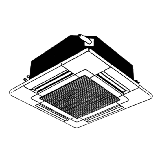
Page 4: Part Names And Functions
PART NAMES AND FUNCTIONS Indoor (Main) Unit PLH-P3AAH.UK, PLH-P4AAH.UK, PLH-P5AAH.UK, PLH-P6AAH.UK PLH-P3AAH .UK, PLH-P4AAH .UK, PLH-P5AAH .UK, PLH-P6AAH Filter Removes dust and pollutants from intake air Horizontal Air Outlet Sets airflow of horizontal automatically during cooling or dehumidifying. Grille Auto Air Swing Vane Disperses airflow up and down and adjusts the angle of airflow direction. -
Page 5: Operation Lamp
Display In this display example on the bot- CENTRALLY display tom left, a condition where all dis- CONTROLLED display play lamps light is shown for expla- The current time , start time and stop nation purposes although this differs time can be displayed in ten second This indicates when the unit is con- intervals by pressing the time setting from actual operation. - Page 6 PLH-P3AAH .UK, PLH-P4AAH .UK, PLH-P5AAH .UK, PLH-P6AAH Operation buttons [ PAR-20MAA-E ] TEMP. ADJUSTMENT button TIME SETTING button AIR SPEED button This sets the room temperature. The This sets the current time, start time This sets the ventilation fan speed. temperature setting can be performed and stop time.
- Page 7 Display In this display example on the bot- CENTRALLY CLOCK display tom left, a condition where all dis- CONTROLLED display play lamps light is shown for expla- The current time , start time and stop time can be displayed in ten second nation purposes although this differs This indicates when the unit is con- intervals by pressing the time switch...
-
Page 8: Wireless Remote Controller
Wireless remote controller PLH-P3AAH.UK, PLH-P4AAH.UK, PLH-P5AAH.UK, PLH-P6AAH.UK When cover is open. [ PAR-SL95A-E ] ADDRESS display display display Displays the refrigerant address. SET TEMP. display indicates desired tempera- Lights up while transmission to the indoor unit ture set. UNIT NO. display is mode using switches. - Page 9 PLH-P3AAH .UK, PLH-P4AAH .UK, PLH-P5AAH .UK, PLH-P6AAH When cover is open. [ PAR-SL97A-E ] display CHECK TEST RUN CHECK&TEST RUN display indicates that the unit is being checked or test-run. display MODEL SELECT Blinks when model is selected. display Lights up while transmission to the indoor unit is mode using switches.
-
Page 10: Specifications
SPECIFICATIONS Service Ref. PLH-P3AAH.UK Item Function Cooling Heating Btu/h 26,600 31,700 [38,900] Capacity 7,800 9,300 [11,400] Total input 3.51 3.65 [5.75] Service Ref. PLH-P3AAH.UK Power supply (phase, cycle,voltage) Single phase, 50Hz, 220–230–240V Input 0.17 0.17 <2.10> Running current w2 0.81 0.81 <8.75>... - Page 11 Service Ref. PLH-P4AAH.UK Item Function Cooling Heating Btu/h 33,100 36,200 [45,000] Capacity 9,700 10,600 [13,200] Total input 3.62 3.80 [6.40] PLH-P4AAH.UK Service Ref. Power supply (phase, cycle,voltage) Single phase, 50Hz, 220–230–240V Input 0.26 0.26 <2.60> Running current w2 1.25 1.25 <10.83> Starting current w2 2.0 <10.83>...
- Page 12 Service Ref. PLH-P5AAH.UK Item Function Cooling Heating Btu/h 43,700 54,600 [64,800] Capacity 12,800 16,000 [19,000] Total input 5.55 5.93 [8.93] Service Ref. PLH-P5AAH.UK Power supply (phase, cycle,voltage) Single phase, 50Hz, 220–230–240V Input 0.30 0.30 <3.00> Running current w2 1.43 1.43 <12.50> Starting current w2 2.0 <12.50>...
- Page 13 Service Ref. PLH-P6AAH.UK Item Function Cooling Heating Btu/h 48,000 57,300 [67,600] Capacity 14,300 16,800 [19,800] Total input 6.70 6.77 [9.77] Service Ref. PLH-P6AAH.UK Power supply (phase, cycle,voltage) Single phase, 50Hz, 220–230–240V (4wires) Input 0.34 0.34 <3.00> Running current w2 1.64 1.64 <12.50>...
- Page 14 Service Ref. PLH-P3AAH.UK / PLH-P3AAH Item Function Cooling Heating Btu/h 26,600 31,700 [38,900] Capacity 7,800 9,300 [11,400] Total input 3.44 3.50 [5.60] Service Ref. PLH-P3AAH.UK / PLH-P3AAH Power supply (phase, cycle,voltage) Single phase, 50Hz, 220–230–240V Input 0.17 0.17 <2.10> Running current w2 0.81 0.81 <8.75>...
- Page 15 Service Ref. PLH-P4AAH.UK / PLH-P4AAH Item Function Cooling Heating Btu/h 33,100 36,200 [43,300] Capacity 9,700 10,600 [12,700] Total input 3.69 3.93 [6.03] Service Ref. PLH-P4AAH.UK / PLH-P4AAH Power supply (phase, cycle,voltage) Single phase, 50Hz, 220–230–240V Input 0.26 0.26 <2.60> Running current w2 1.25 1.25 <10.83>...
- Page 16 Service Ref. PLH-P5AAH.UK / PLH-P5AAH Item Function Cooling Heating Btu/h 43,700 50,800 [61,100] Capacity 12,800 14,900 [17,900] Total input 5.00 5.34 [8.34] Service Ref. PLH-P5AAH.UK / PLH-P5AAH Power supply (phase, cycle,voltage) Single phase, 50Hz, 220–230–240V Input 0.30 0.30 <3.00> Running current w2 1.43 1.43 <12.50>...
- Page 17 Service Ref. PLH-P6AAH.UK / PLH-P6AAH Item Function Cooling Heating Btu/h 48,000 58,300 [68,600] Capacity 14,300 17,100 [20,100] Total input 5.94 6.36 [9.36] Service Ref. PLH-P6AAH.UK / PLH-P6AAH Power supply (phase, cycle,voltage) Single phase, 50Hz, 220–230–240V Input 0.34 0.34 <3.00> Running current w2 1.64 1.64 <12.50>...
-
Page 18: Data
DATA 1. PERFORMANCE DATA 1.1 COOLING CAPACITY (1) PLH-P3AAH.UK / PUH-P3VGA, PUH-P3YGA (240V) Indoor Indoor Outdoor intake air DB (:) intake air intake air P.C. P.C. P.C. DB (:) WB (:) 7,722 4,942 0.64 2.81 7,488 4,792 0.64 2.97 7,254 4,643 0.64 3.14... - Page 19 COOLING CAPACITY (2) PLH-P3AAH.UK / PUH-P3VGA, PUH-P3YGA (240V) Indoor Indoor Outdoor intake air DB (:) intake air intake air DB (:) WB (:) P.C. P.C. P.C. 6,942 4,443 0.64 3.37 6,630 4,243 0.64 3.62 6,318 4,044 0.64 3.91 7,488 3,894 0.52 3.46 7,254...
- Page 20 COOLING CAPACITY (3) PLH-P4AAH.UK / PUH-P4YGA (240V) Indoor Indoor Outdoor intake air DB (:) intake air intake air DB (:) WB (:) P.C. P.C. P.C. 9,603 6,530 0.68 2.90 9,312 6,332 0.68 3.06 9,021 6,134 0.68 3.24 10,282 5,758 0.56 2.95 9,991 5,595...
- Page 21 COOLING CAPACITY (4) PLH-P4AAH.UK / PUH-P4YGA (240V) Indoor Indoor Outdoor intake air DB (:) intake air intake air DB (:) WB (:) P.C. P.C. P.C. 8,633 5,870 0.68 3.48 8,245 5,607 0.68 3.73 7,857 5,343 0.68 4.04 9,312 5,215 0.56 3.57 9,021 5,052...
- Page 22 COOLING CAPACITY (5) PLH-P5AAH.UK / PUH-P5YGA (240V) Outdoor intake air DB (:) Indoor Indoor intake air intake air DB (:) WB (:) P.C. P.C. P.C. 12,672 7,857 0.62 4.44 12,288 7,619 0.62 4.69 11,904 7,380 0.62 4.97 13,568 6,784 0.50 4.52 13,184 6,592 0.50...
- Page 23 COOLING CAPACITY (6) (240V) PLH-P5AAH.UK / PUH-P5YGA Indoor Indoor Outdoor intake air DB (:) intake air intake air DB (:) WB (:) P.C. P.C. P.C. 11,392 7,063 0.62 5.33 10,880 6,746 0.62 5.72 10,368 6,428 0.62 6.19 12,288 6,144 0.50 5.47 11,904 5,952 0.50...
- Page 24 COOLING CAPACITY (7) PLH-P6AAH.UK / PUH-P6YGA (240V) Indoor Indoor Outdoor intake air DB (:) intake air intake air DB (:) WB (:) P.C. P.C. P.C. 14,157 8,353 0.59 5.36 13,728 8,100 0.59 5.66 13,299 7,846 0.59 6.00 15,158 7,124 0.47 5.46 14,729 6,923 0.47...
- Page 25 COOLING CAPACITY (8) PLH-P6AAH.UK / PUH-P6YGA (240V) Indoor Indoor Outdoor intake air DB (:) intake air intake air DB (:) WB (:) P.C. P.C. P.C. 12,727 7,509 0.59 6.43 12,155 7,171 0.59 6.90 11,583 6,834 0.59 7.47 13,728 6,452 0.47 6.60 13,299 6,251 0.47...
- Page 26 COOLING CAPACITY (9) (240V) PLH-P3AAH.UK, PLH-P3AAH .UK / PUH-P3VGAA.UK, PUH-P3YGAA.UK Indoor Indoor Outdoor intake air DB (:) intake air intake air DB (:) WB (:) P.C. P.C. P.C. 7,722 4,942 0.64 2.75 7,488 4,792 0.64 2.91 7,254 4,643 0.64 3.08 8,268 4,299 0.52...
- Page 27 COOLING CAPACITY (10) (240V) PLH-P3AAH.UK, PLH-P3AAH .UK / PUH-P3VGAA.UK, PUH-P3YGAA.UK Indoor Indoor Outdoor intake air DB (:) intake air intake air DB (:) WB (:) P.C. P.C. P.C. 6,942 4,443 0.64 3.30 6,630 4,243 0.64 3.54 6,318 4,044 0.64 3.84 7,488 3,894 0.52...
- Page 28 COOLING CAPACITY (11) (240V) PLH-P4AAH.UK, PLH-P4AAH .UK / PUH-P4VGAA.UK, PUH-P4YGAA.UK Indoor Indoor Outdoor intake air DB (:) intake air intake air DB (:) WB (:) P.C. P.C. P.C. 6,530 0.68 6,332 0.68 6,134 0.68 9,603 2.95 9,312 3.12 9,021 3.30 10,282 5,758 0.56...
- Page 29 COOLING CAPACITY (12) (240V) PLH-P4AAH.UK, PLH-P4AAH .UK / PUH-P4VGAA.UK, PUH-P4YGAA.UK Indoor Indoor Outdoor intake air DB (:) intake air intake air DB (:) WB (:) P.C. P.C. P.C. 8,633 5,870 0.68 3.54 8,245 5,607 0.68 3.80 7,857 5,343 0.68 4.11 9,312 5,215 0.56...
- Page 30 COOLING CAPACITY (13) (240V) PLH-P5AAH.UK, PLH-P5AAH .UK / PUH-P5YGAA.UK Indoor Indoor Outdoor intake air DB (:) intake air intake air DB (:) WB (:) P.C. P.C. P.C. 12,672 7,857 0.62 4.00 12,288 7,619 0.62 4.23 11,904 7,380 0.62 4.48 13,568 6,784 0.50 4.08...
- Page 31 COOLING CAPACITY (14) (240V) PLH-P5AAH.UK, PLH-P5AAH .UK / PUH-P5YGAA.UK Indoor Indoor Outdoor intake air DB (:) intake air intake air DB (:) WB (:) P.C. P.C. P.C. 11,392 7,063 0.62 4.80 10,880 6,746 0.62 5.15 10,368 6,428 0.62 5.58 12,288 6,144 0.50 4.93...
- Page 32 COOLING CAPACITY (15) (240V) PLH-P6AAH.UK, PLH-P6AAH .UK / PUH-P6YGAA.UK Indoor Indoor Outdoor intake air DB (:) intake air intake air DB (:) WB (:) P.C. P.C. P.C. 14,157 8,353 0.59 4.82 13,728 8,100 0.59 5.10 13,299 7,846 0.59 5.40 15,158 7,124 0.47 4.91...
- Page 33 COOLING CAPACITY (16) (240V) PLH-P6AAH.UK, PLH-P6AAH .UK / PUH-P6YGAA.UK Indoor Indoor Outdoor intake air DB (:) intake air intake air DB (:) WB (:) P.C. P.C. P.C. 7,509 0.59 7,171 0.59 6,834 0.59 12,727 5.79 12,155 6.21 11,583 6.72 13,728 6,452 0.47 5.94...
- Page 34 1.2 HEATING CAPACITY PUH-P3VGA, PUH-P3YGA, PUH-P4YGA, PUH-P5YGA, PUH-P6YGA (240V) Outdoor intake air WB (:) Indoor Service Ref. intake air P.C. P.C. P.C. P.C. P.C. P.C. DB (:) 5,906 2.15 6,417 2.37 7,161 2.74 9,393 3.29 10,602 3.65 11,811 3.94 5,673 2.34 6,138 2.56...
- Page 35 Correction factors Cooling capacity correction factors Refrigerant piping length (one way) Service Ref. PLH-P3AAH.UK 1.00 0.981 0.968 0.952 0.940 0.925 0.913 0.900 0.886 0.874 PLH-P3AAH PLH-P4AAH.UIK 0.930 0.920 0.970 0.940 0.910 1.00 0.989 0.980 0.960 0.950 PLH-P4AAH PLH-P5AAH.UK 0.874 1.00 0.981 0.968 0.952...
- Page 36 3. ELECTRICAL DATA Indoor unit ..220V 50Hz Single phase Outdoor unit ..220V 50Hz Single phase / 380V 50Hz 3 phases Model Indoor unit PLH-P4AAH.UK PLH-P3AAH.UK Outdoor unit PUH-P4YGA PUH-P3VGA PUH-P3YGA Cool Heat Cool Heat Cool Heat Mode 9,100 9,100 10,400 7,600...
- Page 37 Indoor unit ..220V 50Hz Single phase Outdoor unit ..380V 50Hz 3 phases Model Indoor unit PLH-P5AAH.UK PLH-P6AAH.UK Outdoor unit PUH-P5YGA PUH-P6YGA Mode Cool Heat Cool Heat 15,800 16,400 Capacity (W) 12,600 14,100 (18,320) (18,920) (In + Out) 5.89 6.73 5.51 6.60...
- Page 38 Indoor unit ..220V 50Hz Single phase Outdoor unit ..220V 50Hz Single phase / 380V 50Hz 3 phases PLH-P3AAH.UK PLH-P4AAH.UK Indoor unit Service PLH-P3AAH PLH-P4AAH Ref. PUH-P•GAA.UK Outdoor unit Cool Heat Cool Heat Cool Heat Cool Heat Mode 9,100 9,100 10,400 10,400...
- Page 39 Indoor unit ..220V 50Hz Single phase Outdoor unit ..380V 50Hz 3 phases PLH-P5AAH.UK PLH-P6AAH.UK Indoor unit Service PLH-P5AAH PLH-P6AAH Ref. PUH-P•GAA.UK Outdoor unit Cool Heat Cool Heat Mode 14,700 16,900 12,600 14,100 Capacity (W) (17,210) (19,420) (In + Out) 5.30 6.33 4.96...
- Page 40 4. STANDARD OPERATION DATA Service Ref. PLH-P3AAH.UK PLH-P4AAH.UK PLH-P5AAH.UK PLH-P6AAH.UK Mode Cooling Heating Cooling Heating Cooling Heating Cooling Heating Capacity 7,800 9,300 9,700 10,600 12,800 16,000 14,300 16,800 Input 3.51 3.65 3.62 3.80 5.55 5.93 6.70 6.77 Indoor unit Service Ref. PLH-P3AAH.UK PLH-P4AAH.UK PLH-P5AAH.UK...
- Page 41 PLH-P6AAH.UK PLH-P3AAH.UK PLH-P4AAH.UK PLH-P5AAH.UK Service Ref. PLH-P6AAH PLH-P3AAH PLH-P4AAH PLH-P5AAH Mode Cooling Heating Cooling Heating Cooling Heating Cooling Heating Capacity 7,800 9,300 9,700 10,600 12,800 14,900 14,300 17,100 Input 3.44 3.50 3.69 3.93 5.00 5.34 5.94 6.36 PLH-P3AAH.UK PLH-P4AAH.UK PLH-P5AAH.UK PLH-P6AAH.UK Indoor unit Service Ref.
- Page 42 6. NOISE CRITERION CURVES PLH-P3AAH.UK NOTCH SPL(dB) LINE PLH-P4AAH.UK NOTCH SPL(dB) LINE PLH-P3AAH PLH-P4AAH NC-70 NC-70 NC-60 NC-60 NC-50 NC-50 NC-40 NC-40 NC-30 NC-30 APPROXIMATE APPROXIMATE THRESHOLD OF THRESHOLD OF HEARING FOR HEARING FOR NC-20 NC-20 CONTINUOUS CONTINUOUS NOISE NOISE 1000 2000 4000...
-
Page 43: Outlines And Dimensions
OUTLINES AND DIMENSIONS PLH-P3AAH.UK, PLH-P4AAH.UK, PLH-P5AAH.UK, PLH-P6AAH.UK Unit: mm PLH-P3AAH .UK, PLH-P4AAH .UK, PLH-P5AAH .UK, PLH-P6AAH Ceiling hole 20 - 45 860 - 910 20 - 45 Branch duct hole Fresh air intake (Cut out hole) Suspension bolt pitch 90 100 100 90 Branch duct hole Branch duct hole... -
Page 44: Wiring Diagram
WIRING DIAGRAM PLH-P3AAH.UK, PLH-P4AAH.UK, PLH-P5AAH.UK, PLH-P6AAH.UK PLH-P3AAH .UK, PLH-P4AAH .UK, PLH-P5AAH .UK, PLH-P6AAH SYMBOL NAME SYMBOL NAME SYMBOL NAME INDOOR POWER BOARD VANE MOTOR WIRELESS REMOTE CONTROLLER BOARD FUSE(4A) DRAIN-UP MACHINE RECEIVING UNIT VARISTOR DRAIN SENSOR BUZZER INDOOR CONTROLLER BOARD DEW PREVENTION HEATER LED1 LED(RUN INDICATOR) -
Page 45: Refrigerant System Diagram
REFRIGERANT SYSTEM DIAGRAM Unit : mm(inch) PLH-P3AAH.UK / PUH-P3VGA, PUH-P3YGA Refrigerant flow in cooling <4-way valve solenoid coil> Refrigerant flow in heating Heating ON Cooling OFF Outdoor unit High pressure Refrigerant pipe 4-way valve switch Indoor unit 15.88 5/8") Thermistor Ball valve (TH6) (with heat insulator) - Page 46 Unit : mm(inch) PLH-P3AAH.UK, PLH-P3AAH .UK / PUH-P3VGAA.UK, PUH-P3YGAA.UK Refrigerant flow in cooling <4-way valve solenoid coil> Refrigerant flow in heating Heating ON Cooling OFF Outdoor unit High pressure Refrigerant pipe 4-way valve protect switch Indoor unit 15.88 5/8") Thermistor Ball valve (TH6) (with heat insulator)
-
Page 47: Troubleshooting
TROUBLESHOOTING HOW TO CHECK THE PARTS PLH-P3AAH.UK, PLH-P4AAH.UK, PLH-P5AAH.UK, PLH-P6AAH.UK PLH-P3AAH .UK, PLH-P4AAH .UK, PLH-P5AAH .UK, PLH-P6AAH Parts name Check points Room temperature Disconnect the connector then measure the resistance using a tester. thermistor (TH1) (Surrounding temperature 10:~30:) Pipe temperature Normal Abnormal thermistor... - Page 48 <Thermistor Characteristic graph> Room temperature thermistor(TH1) Thermistor for < Thermistor for lower temperature > Pipe temperature thermistor(TH2) lower temperature Condenser/evaporator temperature thermistor(TH5) Thermistor R =15k’ ± 3% Fixed number of B=3480k’ ± 2% Rt=15exp { 3480( 273+t 15k’ 9.6k’ 6.3k’ 5.2k’...
-
Page 49: Disassembly Procedure
DISASSEMBLY PROCEDURE PLH-P3AAH.UK, PLH-P3AAH Be careful on removing heavy parts. OPERATING PROCEDURE PHOTOS & ILLUSTRATIONS 1. Removing the air intake grille Figure 1 (1) Slide the knob of air intake grille toward the arrow 1 to open the air intake grille. Air intake grille (2) Remove drop prevention hook from the panel. - Page 50 OPERATING PROCEDURE PHOTOS & ILLUSTRATIONS 5. Remove the fan motor Photo 4 (1) Remove the fan guard.(See photo 1) Fan motor (2) Remove the bell mouth.(See photo 2) (3) Remove the electrical box.(See photo 3) (4) Remove the turbo fan nut. (5) Pull out the turbo fan.
- Page 51 OPERATING PROCEDURE PHOTOS & ILLUSTRATIONS 9. Removing the drain pump and drain sensor Photo 8 (1) Remove the panel. (See photo 6) (2) Remove the fan guard. (See photo 1) (3) Remove the bell mouth. (See photo 2) (4) Remove the electrical box. (See photo 3) (5) Remove the drain pan.
-
Page 52: Parts List
PARTS LIST PLH-P3AAH.UK, PLH-P4AAH.UK, PLH-P5AAH.UK, PLH-P6AAH.UK GEAR PLH-P3AAH .UK, PLH-P4AAH .UK, PLH-P5AAH .UK, PLH-P6AAH GEAR (VANE) VANE BUSH STEPPING MOTOR RECEVER CHECK TEST RUN MODEL SELECT ˚C AMPM AMPM NOT AVAILABLE FILTER CENTRALLY CONTROLLED 1Hr. ON/OFF TEMP ON OFF ˚C CHECK MODE CLOCK CHECK... - Page 53 FUNCTIONAL PARTS PLH-P3AAH.UK, PLH-P4AAH.UK, PLH-P3AAH .UK, PLH-P4AAH THERMAL FUSE SPL WASHER ASSY THERMAL FUSE HEATER THERMAL SWITCH CONDENSER EVAPORATOR TEMPERATURE THERMISTOR PIPE TEMPERATURE THERMISTOR Q'ty / set Price Wiring Recom- Remarks Specification Parts No. Parts Name PLH -P4 PLH -P3 Diagram mended (Drawing No.)
- Page 54 FUNCTIONAL PARTS PLH-P5AAH.UK PLH-P5AAH PLH-P6AAH.UK PLH-P6AAH THERMAL FUSE SPL WASHER ASSY THERMAL FUSE HEATER THERMAL SWITCH CONDENSER EVAPORATOR TEMPERATURE THERMISTOR PIPE TEMPERATURE THERMISTOR Q'ty / set Price Wiring Recom- Remarks Specification Parts No. Parts Name Diagram PLH -P5 PLH -P6 mended (Drawing No.) Symbol...
- Page 55 FUNCTIONAL PARTS PLH-P3AAH.UK, PLH-P4AAH.UK, PLH-P3AAH .UK, PLH-P4AAH DRAIN PLUG DRAIN PLUG CAPACITOR RELAY TERMINAL BLOCK TERMINAL BLOCK TERMINAL BLOCK ROOM TEMPERATURE THERMISTOR Part number that is circled is not shown in the figure. Q'ty / set Price Wiring Recom- Remarks Specification PLH -P3 PLH -P4...
- Page 56 FUNCTIONAL PARTS PLH-P5AAH.UK, PLH-P6AAH.UK PLH-P5AAH .UK, PLH-P6AAH DRAIN PLUG DRAIN PLUG CAPACITOR RELAY TERMINAL BLOCK TERMINAL BLOCK TERMINAL BLOCK ROOM TEMPERATURE THERMISTOR Part number that is circled is not shown in the figure. Q'ty / set Price Wiring Recom- Remarks PLH -P6 PLH -P5 Parts No.
-
Page 57: Optional Parts
OPTIONAL PARTS 1. TIMER Part No. PAC-SC32PTA (with set back function) Model Name Program timer 1-1 Program timer specifications Part name Program timer Parts No. PAC-SC32PTA Exterior dimensions (inch) 5-4/32 4-23/32 23/32 (130 120 18mm) Installation Wall mount Type of clock Quartz Clock accuracy 50 second / month at 25:... - Page 58 1-3. How to connect program timer (1) Install the program timer next to the remote controller the same way as the remote controller is installed. (2) Connect the program timer and the remote controller with a 5-wire cable as shown in the figure below. Connect to indoor unit NOTE:While the program timer is connected to the remote controller, the with 2-wire cable.
- Page 59 2. Multi-Functional Casement Part No. PAC-SG03TM-E Applied Service Ref. PLH-P3/4/5/6AAH.UK, PLH-P3/4/5/6AAH 3. High-Efficiency Filter Element (2. Multi-Functional Casement is needed.) Part No. PAC-SG01KF Applied Service Ref. PLH-P3/4/5/6/AAH.UK, PLH-P3/4/5/6AAH 4. Grille + Wireless Remote Controller Part No. PLP-6AALA PLP-6AALM Applied Service Ref. PLH-P3/4/5/6/AAH.UK PLH-P3/4/5/6AAH 5.
- Page 60 HEAD OFFICE : MITSUBISHI DENKI BLDG., 2-2-3, MARUNOUCHI CHIYODA-KU, TOKYO100-8310, JAPAN cCopyright 2001 MITSUBISHI ELECTRIC ENGINEERING CO., LTD. Distributed in Sep. 2001 NO. OC236 REVISED EDITION-A 250 New publication, effective Sep. 2001 Distributed in Apr. 2001 NO. OC236 225 Specifications subject to change without notice...