Bosch ZBR16-3A Series Installation And Service Instructions Manual
Greenstar
Hide thumbs
Also See for ZBR16-3A Series:
- Installation and service instructions manual (120 pages) ,
- Operating instructions manual (48 pages) ,
- Manual (4 pages)
Table of Contents
Advertisement
Quick Links
Residential Gas Condensing Boiler
Greenstar
ZBR16-3A... | ZBR21-3A... | ZBR28-3A... | ZBR35-3A... | ZBR42-3A... | ZWB28-3A... | ZWB35-3A... | ZWB42-3A...
Installation and Service Instructions for Contractors
WARNING:
Improper installation, set-up, modification, operation or maintenance
of the heating system can cause personal injury and property damage.
Follow these instructions precisely.
If you require assistance or further information, contact a trained and
certified installer or the gas supply company.
WARNING:
The operating instructions are part of the technical documents that
must be handed over to the owner or operator of the heating system.
Explain to the owner or operator how to use the heating system using
the operating instructions. Make sure that they are familiar with all
required information for the safe and proper operation of the heating
system.
NOTICE:
In Massachusetts, this appliance must be installed by a licensed
plumber or gas fitter.
These instructions are available in English and French.
Please keep these instructions for future reference.
6 720 806 992-00-1O
Advertisement
Table of Contents

Related Manuals for Bosch ZBR16-3A Series


Summary of Contents for Bosch ZBR16-3A Series
- Page 1 WARNING: Improper installation, set-up, modification, operation or maintenance of the heating system can cause personal injury and property damage. Follow these instructions precisely. If you require assistance or further information, contact a trained and certified installer or the gas supply company. WARNING: The operating instructions are part of the technical documents that must be handed over to the owner or operator of the heating system.
-
Page 2: Table Of Contents
2 | Contents Selecting the installation location ....34 Contents Pre-installing pipes ......34 Mounting the appliance . -
Page 3: Key To Symbols And Safety Instructions
Key to symbols and safety instructions | 3 ZBR..-3A appliances (heating boiler) with DHW tank: 17 Faults ..........76 Thermal disinfection . -
Page 4: General Safety Instructions
4 | Key to symbols and safety instructions General safety instructions ▶ Do not tamper with, remove, or attempt to repair the blocked vent switch. If you hear gas leaking ▶ When replacing the blocked vent switch, install the new part in the ▶... -
Page 5: Scope Of Delivery
Scope of delivery | 5 NOTICE: Scope of delivery ▶ Upon completion of the installation, these instructions should be handed to the owner and operator of the appliance. ZBR - Residential boiler for space heating and loading ▶ The installer must instruct the owner and operator on the functionality of indirect fired DHW tanks of the components and the proper operation of the boiler and the heating system. -
Page 6: Zwb - Residential Combi Boiler For Space Heating And Dhw Generation
6 | Scope of delivery ZWB - Residential combi boiler for space heating and DHW generation Contents of package 1: Gas condensing boiler Set of documents for appliance Mounting bracket with mounting kit Gas conversion kit Adapter for connection of a LWCO Contents of package 2: Rail with connection box Flue adapter... -
Page 7: Information About The Appliance
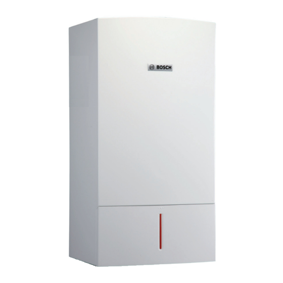
Information about the appliance | 7 Rating plate Information about the appliance The rating plate is located at the right side of the appliance. ZBR appliances are residential boilers for central heating and loading of an indirect fired DHW tank. ZWB appliances are residential combi boilers for central heating and on demand DHW heating. -
Page 8: Accessories
8 | Information about the appliance Accessories Here you will find a list of typical accessories for this appliance. Refer to the Bosch Product Catalog for a complete overview of all available accessories. • FB 100 room control • Modules for system expansions: –... -
Page 9: Product Dimensions And Minimum Clearances
Information about the appliance | 9 Product dimensions and minimum clearances ≥ 4" * ≥ 4" * (102 mm) * (102 mm) * 17-21/64" (440 mm) 3-11/32" (85 mm) ≥ 4" ** (102 mm) ** 9-29/64" (240 mm) 13-57/64" (353 mm) "... -
Page 10: Appliance Layout Heating Boiler Zbr
10 | Information about the appliance Appliance layout heating boiler ZBR..-3A 6 720 641 933-02.2O Fig. 5 Appliance layout heating boiler ZBR..-3A 6 720 806 992 (2015/03) Greenstar... - Page 11 Information about the appliance | 11 Key to Fig. 5: Heatronic boiler control ON/OFF switch Burner flame indicator Service button Emissions test button Boiler high limit dial Mounting socket for outdoor reset controls DHW thermostat Key pad lock [10] ECO button [11] Reset button [12] Display [13] Condensate trap...
-
Page 12: Appliance Layout Combi Boiler Zwb
12 | Information about the appliance Appliance layout combi boiler ZWB..-3A 6 720 641 933-03.2O Fig. 6 Appliance layout combi boiler ZWB..-3A 6 720 806 992 (2015/03) Greenstar... - Page 13 Information about the appliance | 13 Key to Fig. 6: Heatronic boiler control ON/OFF switch Burner flame indicator Service button Emissions test button Boiler high limit dial Mounting socket for outdoor reset controls DHW thermostat Key pad lock [10] ECO button [11] Reset button [12] Display [13] Condensate trap...
-
Page 14: Electrical Wiring Heating Boiler Zbr
14 | Information about the appliance Electrical wiring heating boiler ZBR..-3A LS NS 6 720 641 933-23.3O Fig. 7 Electrical wiring diagram heating boiler ZBR..-3A 6 720 806 992 (2015/03) Greenstar... - Page 15 Information about the appliance | 15 Key to Fig. 7: Ignition transformer Boiler high limit dial 120 VAC connection DHW tank primary pump or 3-way valve External heating pump for unmixed heating circuit (secondary circuit) or DHW recirculation pump Fuse T 6.3 A (120 VAC) DHW thermostat External safety high limit or low water cut off (LWCO) BUS connection, e.g.
-
Page 16: Electrical Wiring Combi Boiler Zwb
16 | Information about the appliance 3.10 Electrical wiring combi boiler ZWB..-3A LS NS 6 720 641 933-24.3O Fig. 8 Electrical wiring diagram combi boiler ZWB..-3A 6 720 806 992 (2015/03) Greenstar... - Page 17 Information about the appliance | 17 Key to Fig. 8: Ignition transformer Boiler high limit dial 120 VAC connection External heating pump for unmixed heating circuit (secondary circuit) or DHW recirculation pump Fuse T 6.3 A (120 VAC) DHW thermostat External safety high limit or low water cut off (LWCO) BUS connection, e.g.
-
Page 18: Technical Data Heating Boiler Zbr16-3A
18 | Information about the appliance 3.11 Technical data heating boiler ZBR16-3A... Input/Output Unit LPG (propane) Max. input rate 180/79 °F (82/26 °C) BTU/hr (kW) 57,200 (16.8) 56,400 (16.5) Max. output rate 104/86 °F (40/30 °C) BTU/hr (kW) 54,900 (16.1) 55,300 (16.2) Max. -
Page 19: Technical Data Heating Boiler Zbr21-3A
Information about the appliance | 19 3.12 Technical data heating boiler ZBR21-3A... Input/Output Unit LPG (propane) Max. input rate 180/79 °F (82/26 °C) BTU/hr (kW) 79,200 (23.2) 77,500 (22.7) Max. output rate 104/86 °F (40/30 °C) BTU/hr (kW) 74,700 (21.9) 74,700 (21.9) Max. -
Page 20: Technical Data Heating Boiler Zbr28-3A
20 | Information about the appliance 3.13 Technical data heating boiler ZBR28-3A... Input/Output Unit LPG (propane) Max. input rate 180/79 °F (82/26 °C) BTU/hr (kW) 100,800 (29.5) 98,600 (28.9) Max. output rate 104/86 °F (40/30 °C) BTU/hr (kW) 93,800 (27.5) 93,800 (27.5) Max. -
Page 21: Technical Data Heating Boiler Zbr35-3A
Information about the appliance | 21 3.14 Technical data heating boiler ZBR35-3A... Input/Output Unit LPG (propane) Max. input rate 180/79 °F (82/26 °C) BTU/hr (kW) 131,900 (38.6) 129,100 (37.8) Max. output rate 104/86 °F (40/30 °C) BTU/hr (kW) 122,800 (36.0) 122,800 (36.0) Max. -
Page 22: Technical Data Heating Boiler Zbr42-3A
22 | Information about the appliance 3.15 Technical data heating boiler ZBR42-3A... Input/Output at elevation 0 - 2000 feet (0 - 610 m) Unit LPG (propane) Max. input rate 180/79 °F (82/26 °C) BTU/hr (kW) 151,600 (44.4) 148,300 (43.5) Max. output rate 104/86 °F (40/30 °C) BTU/hr (kW) 137,500 (40.3) 137,500 (40.3) -
Page 23: Technical Data Combi Boiler Zwb28-3A
Information about the appliance | 23 3.16 Technical data combi boiler ZWB28-3A... Input/Output Unit LPG (propane) Max. input rate 180/79 °F (82/26 °C) BTU/hr (kW) 100,800 (29.5) 98,600 (28.9) Max. output rate 104/86 °F (40/30 °C) BTU/hr (kW) 93,800 (27.5) 93,800 (27.5) Max. -
Page 24: Technical Data Combi Boiler Zwb35-3A
24 | Information about the appliance 3.17 Technical data combi boiler ZWB35-3A... Input/Output Unit LPG (propane) Max. input rate 180/79 °F (82/26 °C) BTU/hr (kW) 131,900 (38.6) 129,100 (37.8) Max. output rate 104/86 °F (40/30 °C) BTU/hr (kW) 122,800 (36.0) 122,800 (36.0) Max. -
Page 25: Technical Data Combi Boiler Zwb42-3A
Information about the appliance | 25 3.18 Technical data combi boiler ZWB42-3A... Input/Output at elevation 0 - 2000 feet (0 - 610 m) Unit LPG (propane) Max. input rate 180/79 °F (82/26 °C) BTU/hr (kW) 151,600 (44.4) 148,300 (43.5) Max. output rate 104/86 °F (40/30 °C) BTU/hr (kW) 137,500 (40.3) 137,500 (40.3) -
Page 26: Condensate Composition
26 | Regulations Input/Output at elevation 0 - 2000 feet (0 - 610 m) Unit LPG (propane) Condensate Max. condensate quantity (t = 86 °F (30 °C)) gph (l/h) 0.9 (3.5) 0.9 (3.5) pH level, approx. – General Voltage Frequency Max. -
Page 27: Additional Regulations For Installation In Massachusetts
Regulations | 27 Additional regulations for installation in instructions provided by the manufacturer for the installation of the equipment and venting shall include: Massachusetts • Detailed instructions for the installation of the venting system or the (a) For all side wall horizontally vented gas fueled equipment installed in venting system components;... -
Page 28: Common Applications Of Zbr Boilers
28 | Common Applications of ZBR boilers Common Applications of ZBR boilers Multiple zones using zone valves with DHW ϑ 6 720 806 992-03.1O Fig. 9 Piping To heating zone 2 Motorized valve heating zone 2 To heating zone 1 Motorized valve heating zone 1 System pump DHW pump... - Page 29 Common Applications of ZBR boilers | 29 24VAC T T COM LS NS 6 720 806 992-04.1O Fig. 10 Wiring PCB in heating boiler ZBR..-3A... with FW 200 installed on front White plug for mains power supply, 120 V AC, 60 Hz (...
-
Page 30: Multiple Zones Using Circulators With Dhw
30 | Common Applications of ZBR boilers Multiple zones using circulators with DHW ϑ 6 720 806 992-05.1O Fig. 11 Piping To heating zone 2 Pump heating zone 2 To heating zone 1 Pump heating zone 1 To indirect tank DHW pump External system supply temperature sensor for system supplypipe (to be installed in closest vicinity with... - Page 31 Common Applications of ZBR boilers | 31 Zone 1 Zone 2 Zone 3 Zone 4 Power LS NS 6 720 806 992-06.1O Fig. 12 Wiring PCB in heating boiler ZBR..-3A... with FW 200 installed on front White plug for mains power supply, 120 V AC, 60 Hz (...
-
Page 32: Installation
Water Chemistry Guidelines ▶ Empty out sediment traps. NOTICE: Insufficient antifreeze can accelerate ▶ Systems containing antifreeze not approved by Bosch, must be corrosion. completely flushed to ensure no old fluid remains. ▶ Follow manufacturer's instructions on antifreeze ▶... -
Page 33: Other Important Information
Installation | 33 The following anti-freeze fluids and concentrations have been approved: • Inspect the sewer pipes for suitability before disposing of untreated boiler condensate into them. Chemical Name Concentration • Verify with the local authority that disposing of untreated boiler Nalco (Varidos) FSK 22 - 55 % condensate into public sewer systems is permitted. -
Page 34: Zbr
34 | Installation ZBR..-3A appliances (heating boilers): Selecting an Surface temperature expansion vessel The max. surface temperature of this appliance is below 185 °F (85 °C). According to ANSI/Z223.1/NFPA43 (National fuel gas code) and CAN/ External expansion vessel CGA B 149.1 (Natural Gas and Propane installation code), the appliance ▶... - Page 35 Installation | 35 ▶ Secure the hydraulics connection plate and the mounting bracket with the mounting kits supplied. 5 1/8" (130 mm) 10 15/64" (260 mm) 6 720 641 933-15.1O Fig. 19 Hydraulics connection plate for heating boiler ZBR..-3A (top view) 7 7/8"...
-
Page 36: Mounting The Appliance
• Hydrolevel Safgard 1100 ( page 10). The device is available at most Bosch wholesalers. It requires an Removing the cover external 24VAC 20VA transformer provided on site. -
Page 37: Connecting Flue Gas Accessories
• Twin pipe PP 2" (50 mm )/ 3" (80 mm) (M&G Duravent PolyPro and To avoid premature wear of the gaskets DO NOT use Centrotherm InnoFlue) lubricants. • Concentric PP 3" / 5" (80/125 mm) (Bosch) Greenstar 6 720 806 992 (2015/03) -
Page 38: Installation Of The Exhaust And Air Intake System
As an alternative to twin pipe venting, a purposely designed and built telescopic concentric vent kit can be DANGER: obtained as an accessory from Bosch Thermotechnology ▶ Ensure that the flue pipes and seals are not damaged. for a horizontal direct vent wall termination. This vent ▶... - Page 39 M&G Approved Polypropylene Duravent PolyPro and Centrotherm InnoFlue PP rigid venting 3"/5" (80/125 mm) ANSI Cat IV concentric (Bosch, Approved Polypropylene manufactured by PP rigid venting ANSI Cat IV M&G Duravent) Approved Polypropylene Table 17 Materials for pipe...
- Page 40 M&G Duravent PolyPro 3PPS-HTP Ø 3" (Ø 76 mm) single pipe termination M&G Duravent PolyPro 3PPS-HST Ø 3" / Ø 5" (Ø 80/125 mm) Bosch Greenstar Bosch (manufactured by 7738003218 Horizontal Telescopic Terminal Kit M&G Duravent) Table 19 Wall terminals NOTICE: ▶...
- Page 41 Installation | 41 NOTICE: NOTICE: ▶ Vent terminations must keep the following minimum ▶ For Clearances not specified in ANSI Z223.1 / clearances from electric meters, gas meters, NFPA 54 or CSA B149.1. regulators and relief equipment: 4 feet (1220 mm) ▶...
-
Page 42: Approved Examples Of Horizontal And Vertical Venting Installation
42 | Installation 6.8.2 Approved examples of horizontal and vertical venting installation ≥ 4" (102 mm) NOTICE: ▶ Place pipe supports every 5 feet (1 525 mm) of horizontal and vertical run, beginning with support near boiler. ▶ The condensate must be disposed of in accordance with applicable rules. - Page 43 Installation | 43 6 720 641 933-09.2O Fig. 36 Vertical venting system (sealed combustion) 6 720 641 933-10.1O 6 720 641 933-07.1O Fig. 37 Vertical venting system (room air only) Fig. 38 Vertical venting system (sealed combustion) Key to Fig. 36, Fig. 37 and Fig. 38: Intake Exhaust Concentric termination...
-
Page 44: Vent And Combustion Air Pipe Lengths
44 | Installation 1/4" per foot (50 mm per meter) 6 720 641 933-78.1O Fig. 41 Horizontal venting system (telescopic concentric vent kit) 6.8.3 Vent and combustion air pipe lengths With Flex Pipe the maximum length is reduced by 50%. Flex Pipe according to the suppliers instructions for use in the vertical part of the installation only. -
Page 45: Testing Gas And Water Connections For Leaks
Making the electrical connections | 45 Installations Fig. 35 Stainless steel wall termination Fitting Equivalent 2" PIPE Maximum straight vent pipe length allowed for Ø 2" pipe 45 ° elbow 0.91 ZBR16-3A ZBR35-3A 90 ° elbow 1.82 ZBR21-3A ZWB35-3A Table 24 Concentric pipe friction loss equivalent for fittings Number of 90 °... -
Page 46: Low Voltage Electrical Connections In The Heatronic Boiler Control
46 | Making the electrical connections ▶ Remove screws (step 1), unhook cable and remove cover (step 2). Provide a dedicated circuit breaker for the boiler and heating system rated at least 15A. All line voltage wiring must use at least AWG14 size cables. All appliance modulation, control and safety components are tested and pre-wired for use. -
Page 47: Connecting The Dhw Tank Temperature Sensor (Only Heating Boiler Zbr
Bosch room controls Fig. 48 Mounting supply temperature sensor right next to boiler supply Connect only Bosch room controls to the internal BUS of this boiler. System secondary line – supply pipe For installation and electrical connection of the FB 100 remote control, Supply temperature sensor for system supply pipe see installation instructions for the remote control. -
Page 48: Electrical Connections In The Junction Box (120 Vac)
48 | Making the electrical connections Electrical connections in the junction box (120 VAC) 7.3.1 Mounting rails for junction box ▶ Hold the rail against the appliance from below (step 1) and fasten with the screws from the outside or inside (step 2). ▶... -
Page 49: Dhw Tank Loading Pump Or 3-Way Valve With Spring Return (Only Heating Boiler Zbr
▶ Route the power cable (AC 120 V, 60 Hz) from the emergency shutoff switch to the boiler. The DHW recirculation pump is controlled by the Bosch ▶ Insert cable into the junction box as shown in Fig. 57. FW 200. -
Page 50: Connecting The Lwco Device
50 | Making the electrical connections ▶ Connect white plugs and insert grommet until stop. ▶ Connect the leads labeled SWITCH CONTACT (yellow) to the TB1 temperature guard ( Fig 47, page 47) on the Heatronic. 6 720 641 933-67.1O Fig. -
Page 51: Commissioning
Commissioning | 51 Commissioning eco reset 6 720 641 933-25.1O Fig. 60 Overview of the controls Emissions test button Before operating the appliance Service button Burner operation indicator lamp NOTICE: Commissioning without being properly filled ON/OFF power switch and purged will damage the appliance. Key pad lock ▶... -
Page 52: Switching The Appliance On/Off
52 | Commissioning Switching the appliance ON/OFF With radiant floor heating, limit the maximum Startup permissible supply temperature as recommended by the manufacturer. ▶ Switch the appliance ON using the ON/OFF switch. The display indicates the supply temperature of the hot water in °F. If necessary, convert to °C (... -
Page 53: Fw 200 Heating Control Quick Start
Commissioning | 53 Legend to Fig. 63: ▶ Press the dial Program will be highlighted. Dial Mode selector ▶ Press the dial Advance button (activate heating immediately) Activate will be highlighted. DHW single charge button (activate DHW mode immediately) ▶ Turn the dial one click to highlight Edit. -
Page 54: Adjusting Warm Weather Shut Down (Wwsd)
54 | Commissioning ▶ Turn the dial until Design Temp will be highlighted. ▶ Press the dial and the display will fl ash. The default value is 68 °F (20 °C) and is adjustable from 50 °F (10 °C) ▶ Press the dial to 77 °F (25 °C). -
Page 55: Zbr
Commissioning | 55 ZBR..-3A appliances (heating boilers) with DHW tank: ZWB..-3A appliances (combi boilers): Setting the DHW temperature Setting the DHW temperature ▶ Set the DHW temperature on the DHW thermostat ▶ Set the DHW temperature on the DHW thermostat The set DHW temperature flashes on the display for 30 seconds. -
Page 56: Setting Frost Protection
▶ Carry out thermal disinfection only outside the normal hours of use, or install a tempering valve. ▶ Mix Bosch-approved anti-freeze into the heating water ( Tab. 14, page 32) and drain the DHW circuit. ▶ Close all DHW taps. -
Page 57: Boiler Circulator
Boiler circulator | 57 Boiler circulator 10.1 Pump anti-seize protection This function prevents the heating zone pump from seizing up following longer idle periods. The appliance will briefly run the pump at least every 24 hours after its last activation. 10.2 Changing the pump curve of the boiler pump The speed of the boiler pump can be changed using the dial on the pump. -
Page 58: Heatronic Boiler Control Settings
58 | Heatronic boiler control settings ▶ Press and hold the service button until it illuminates. The display Heatronic boiler control settings shows a code such as 1.A (first service level). Press the ECO button and key pad lock button simultaneously until the code 8.A appears 11.1 Guideline to service functions (second service level). -
Page 59: Second Service Level (At First Service Level, Service Button Lights Up, Press Eco Button And Key Pad Lock Button Simultaneously Until 8.A Appears)
Heatronic boiler control settings | 59 11.2.2 Second service level (at first service level, service button Service function 1.b: Maximum DHW output lights up, press ECO button and key pad lock button The hot water output can be adjusted between the minimum and simultaneously until 8.A appears) maximum DHW outputs to suit the heat transfer capacity of the DHW tank coil. - Page 60 60 | Heatronic boiler control settings Service function 2.A: Heating circuit pump lockout time (only Service function 2.d: Thermal disinfection (legionella protection) heating boiler ZBR..-3A) WARNING: Risk of scalding! NOTICE: System damage or boiler malfunction! Hot water can result in severe scalding. ▶...
- Page 61 Heatronic boiler control settings | 61 Service function 3.b: Set anti-cycle time Service function 3.F: Constant DHW period (only combi boiler ZWB..-3A) Only if the automatic anti-cycle time is disabled (service function 3.A) will this function be active. NOTICE: System damage or boiler malfunction! ▶...
- Page 62 62 | Heatronic boiler control settings Service function 4.F: Condensate trap filling sequence Service function 5.F: Set inspection interval This service function allows setting the number of months after which DANGER: Risk of flue gas poisoning! the 'service due' reminder appears on the display alternating with If the condensate trap is not filled, flue gas may escape the supply temperature.
-
Page 63: Second Service Level
(or vice versa), the code plug must be replaced. Service function 8.C: GFA Gas burner control unit status Internal parameter. If you are on the line with Bosch Technical Support you may be asked for this number. Service function 8.d: GFA Gas burner control unit fault Internal parameter. - Page 64 64 | Heatronic boiler control settings Service function 8.E: Restore boiler to factory settings Default setting is 50. This function allows resetting all parameters of the boiler including all service functions to their factory settings. Service function 9.E: Turbine signal delay ▶...
-
Page 65: Gas Type Conversion
6000 feet (1829 m). Above 6000 feet (1829 m) a rate of 3 % per 1000 feet (305 m) applies. The Bosch Greenstar boiler is factory set for installation below 2000 feet (610 m) above sea level. ▶ Correction of the fan speed curve of the burner: Use service function 0.d to adjust the elevation setting (... -
Page 66: Setting The Gas-Air Ratio (Co 2 Or O 2 )
66 | Gas type conversion 12.3 Setting the gas-air ratio (CO or O ▶ Adjust the gas throttle to match the CO or O level for maximum nominal output according to table 31. ▶ Switch the appliance OFF using the ON/OFF switch. ▶... -
Page 67: Dynamic Gas Pressure Test
Gas type conversion | 67 ▶ Remove flue gas probe and close the flue gas test port properly. 12.4 Dynamic gas pressure test ▶ Switch the appliance OFF and close the gas shut-off valve. ▶ Loosen the screw in the test port for gas inlet pressure (... -
Page 68: Flue Gas Test
Environmental responsibility/disposal Environmental responsibility is one of the fundamental company 13.1 Emissions test button policies of the Bosch Group. The following appliance outputs can be selected by pressing the We regard quality of performance, economy and environmental emissions test button until it lights up: responsibility as equal objectives. -
Page 69: Description Of Various Steps
(step 2), and remove the filter from the pipe (step 3). commissioning. ▶ If necessary, clean with plastic brush under running water. ▶ Only use a Bosch cleaning blade or Bosch cleaning brush ( page 98). ▶ Only clean heat exchanger if soiling is clearly visible. -
Page 70: Checking The Electrodes
70 | Inspection and maintenance ▶ Loosen/remove pipe connections. ▶ Remove the plate type heat exchanger. 6 720 641 933-50.2O Fig. 89 Removing the plate heat exchanger ▶ Install new plate type heat exchanger with new gaskets and reconnect the hydraulic assembly in reverse order. ▶... -
Page 71: Burner Servicing
▶ Cleaning of the heat exchanger should not be necessary until five years after the initial commissioning. ▶ Only use a Bosch cleaning blade and Bosch cleaning ▶ Remove burner lid (steps 1 - 4). brush ( page 98). ▶ Only clean heat exchanger in case if soiling is clearly visible. - Page 72 72 | Inspection and maintenance ▶ With the cleaning blade, clean the heat exchanger block from the ▶ Rinse the heat exchanger with water from the top. bottom to the top. 6 720 612 664-18.1R Fig. 97 Rinsing the heat exchanger ▶...
-
Page 73: Condensate Trap Cleaning
Inspection and maintenance | 73 15.1.7 Condensate trap cleaning ▶ Insert the diaphragm into the fan connector. Ensure the diaphragm is oriented properly. ▶ Remove condensate trap (steps 1 and 2) and check heat exchanger orifice for clear passage. The diaphragm flaps must open upwards. ▶... -
Page 74: Checklist For Inspection And Maintenance
74 | Inspection and maintenance 15.2 Checklist for inspection and maintenance ▶ Use this form to guide you through the service and maintenance procedure. Fill out each step according to the findings and work performed. Date Latest fault code from service function 6.A ( page 69). Fresh water inlet filter (Combi boiler ZWB appliances only) (... -
Page 75: Readings On The Display
Readings on the display | 75 Status code Description Readings on the display Acknowledge by pressing any button (except reset). The boiler display can provide the following information (Tab. 36 and 37): Acknowledge by pressing two buttons Value displayed Description Range simultaneously Number or letter, dot... -
Page 76: Faults
76 | Faults If the fault persists: Faults ▶ Check the PCB and replace if required. Adjust the service functions in accordance with the commissioning report ( page 81). 17.1 Troubleshooting DANGER: Explosion! ▶ Close the gas cock prior to working on the gas train. ▶... -
Page 77: Faults That Are Shown On The Display
Faults | 77 17.2 Faults that are shown on the display Display Description Elimination DHW temperature sensor defective. ▶ Check temperature sensor and leads for interruptions or shorts, and replace if defective. ▶ Insert code plug correctly; replace if defective. Communication fault. - Page 78 78 | Faults Display Description Elimination No flame detected. ▶ Check that ground lead is properly connected, replace if defective. ▶ Check that gas cock is open. ▶ Check inlet gas pressure; correct if needed. ▶ Check power supply. ▶ Check electrodes for visual damage; replace if defective. ▶...
-
Page 79: Faults That Are Not Shown On The Display
Faults | 79 17.3 Faults that are not shown on the display Appliance faults Elimination Combustion noise too loud; rumbling noises ▶ Insert code plug correctly; replace if defective. ▶ Check gas type. ▶ Check inlet gas pressure; adjust if defective. ▶... -
Page 80: Check Sensor Values
80 | Faults 17.4 Check sensor values 17.4.3 Supply temperature sensor, External supply temperature sensor, DHW tank temperature sensor, DHW temperature 17.4.1 Outdoor temperature sensor sensor Temperature °F ( °C) Temperature °F ( °C ) Testing tolerance 10% Testing tolerance 10% Resistance [... -
Page 81: Commissioning Log For The Appliance
Commissioning log for the appliance | 81 Commissioning log for the appliance Home owner/operator: Last name, first name Number, Street Telephone/fax ZIP code, town System installer: Order number: Appliance type: (Complete a separate log for every appliance!) FD (Date of manufacture): Date commissioned: ... - Page 82 82 | Commissioning log for the appliance Modified service functions: (Select the modified service functions and enter the values here.) Example: Service function 7.d changed from 00 to 01 Heating control: FW 200 FB 100 × ..Qty, coding heating zone(s): ...
-
Page 83: Spare Parts
Spare parts | 83 Spare parts ▶ Order spare parts by name and part number using the spare parts list. Designation Spare parts list page 84 Group 1 - Sheet metal ... - Page 84 84 | Spare parts 6 720 641 933-102.2O Fig. 101 Group 1 - Sheet metal Greenstar 6 720 806 992 (2015/03) Greenstar...
- Page 85 Spare parts | 85 Item ( Fig. 101) Designation Order number Outer jacket complete 8 737 702 514 0 Front cover 8 718 222 827 0 ...
- Page 86 86 | Spare parts 6 720 641 933-103.3O Fig. 102 Group 2 - Burner/Heat exchanger Greenstar 6 720 806 992 (2015/03) Greenstar...
- Page 87 Spare parts | 87 Item ( Fig. 102) Designation Order number Heat exchanger block (incl. set of gaskets) incl. flue gas and 8 737 701 797 0 condensate collector (item 4) ...
- Page 88 88 | Spare parts 6 720 641 933-104.1o Fig. 103 Group 3 - Gas valve Greenstar 6 720 806 992 (2015/03) Greenstar...
- Page 89 Spare parts | 89 Item ( Fig. 103) Designation Order number Fan RG130 USA 8 718 226 185 0 Diaphragm 8 715 505 928 0 ...
- Page 90 90 | Spare parts 6 720 641 933-105.1o Fig. 104 Group 4 - Pipes combi boiler ZWB..-3A Greenstar 6 720 806 992 (2015/03) Greenstar...
- Page 91 Spare parts | 91 Item ( Fig. 104) Designation Order number Condensate trap complete 8 710 506 271 0 Cup incl. gasket 8 710 506 273 0 Drain hose 8 710 703 178 0 ...
- Page 92 92 | Spare parts 6 720 641 933-106.2O Fig. 105 Group 5 - Pipes heating boiler ZBR..-3A Greenstar 6 720 806 992 (2015/03) Greenstar...
- Page 93 Spare parts | 93 Item ( Fig. 105) Designation Order number Condensate trap complete 8 710 506 271 0 Cup incl. gasket 8 710 506 273 0 ...
- Page 94 94 | Spare parts 6 720 641 933-107.3O Fig. 106 Group 6 - Control box Greenstar 6 720 806 992 (2015/03) Greenstar...
- Page 95 System supply temperature sensor 8 737 700 289 0 FW200 Bosch USA en-us, fr, es, de 8 718 226 215 0 Outdoor temperature sensor 8 747 207 101 0 ...
- Page 96 96 | Spare parts 6 720 641 933-108.2O Fig. 107 Group 7 - Hydraulic block combi boiler ZWB..-3A Greenstar 6 720 806 992 (2015/03) Greenstar...
- Page 97 Spare parts | 97 Item ( Fig. 107) Designation Order number Flat plate heat exchanger 20 plates 8 716 108 212 0 Flat plate heat exchanger gasket 15mm 8 716 106 435 0 ...
- Page 98 98 | Spare parts Item Designation Order number – Brush set WB5 7 719 002 502 – Cleaning blade WB5 7 719 002 503 Table 52 Group 8 - Accessories for service/installation Greenstar 6 720 806 992 (2015/03) Greenstar...
-
Page 99: Index
Index | 99 Index Default settings ............... 54 Details about the appliance Proper use ................7 Scope of delivery..............5 Accessories ................8 Technical specifications Anti-freeze ................32 - ZBR16-3A..............18 Appliance description ..............7 - ZBR21-3A..............19 Appliance details ................ 9 - ZBR28-3A.............. - Page 100 100 | Index Heating control ................ 52 Old appliances................. 68 Heatronic Open vented heating systems ............ 32 Service functions ............. 58–64, 69 Operating conditions ..........18–20, 23–25 Settings................58 Operating pressure of the boiler ..........73 Overview of the service functions ..........58 Information about the appliance ...........
- Page 101 Index | 101 Connecting an external supply temperature sensor Set functionality of black plug (connection NZ - LZ) (service function 7.d) ............63 (service function 5.E) ............62 Constant mode Set start speed 1 (service function 9.A) ............64 (service function 9.d) ............64 Current fan speed Software version (service function 9.b) ............
- Page 102 102 | Index 6 720 806 992 (2015/03) Greenstar...
- Page 103 Index | 103 Greenstar 6 720 806 992 (2015/03)