Table of Contents
Advertisement
Quick Links
SERVICE MANUAL
VIDEO CASSETTE RECORDER
POWER
1
2
3
4
5
6
7
8
9
+
0
(AUX)
–
CH
REC
PAUSE
PLAY
REW
FF
MENU
ENTER
STOP
–
+
SET
CANCEL
TV/VCR
TIMER
C.RESET
A.MONITOR
SP/EP
DISPLAY
–
+
TV POWER
TV CH
–
+
INPUT
TV VOL
SPECIFICATIONS
GENERAL
: AC 110 V-220 V~, 50 Hz/60 Hz
Power requirement
Power consumption
: 10 W
Power on
: 2.0 W
Power off
Temperature
: 5°C to 40°C (41 °F to 104°F)
Operating
:–20°C to 60°C (–4°F to140°F)
Storage
: Horizontal only
Operating position
: 360 mm x 95 mm x 224 mm
Dimensions (W x H x D)
: 3.2 kg
Weight
: VHS NTSC standard
Format
Maximum recording time
: 210 min. with ST -210 video cassette
SP
: 630 min. with ST -210 video cassette
EP
VIDE O/AUDIO
: NTSC-type color signal and
Signal system
E IA monochrome signal, 525 lines/60 fields
Recording/Playback
: DA-4
system
(Double Azimuth) head helical scan system
: 42 dB
Signal-to-noise ratio
: 230 lines
Horizontal resolution
Frequency range
: 100 Hz to 10,000 Hz
Normal audio
: 20 Hz to 20,000 Hz
Hi-Fi audio
:RC A connectors (IN x 1, OUT x 1)
Input/Output
HR-J6009UM
POWER
VIDEO (MONO) L – AUDIO – R
This service manual is printed on 100% recycled paper.
COPYRIGHT © 2002 VICTOR COMPANY OF JAPAN, LTD
PLAY
STOP/EJECT
REW
FF
CH
REC
TUNER
: Frequency-synthesized tuner
Tuning system
Channel coverage
: Channels 2–13
VHF
: Channels 14– 69
UHF
: 113 Channels
CATV
: Channel 3 or 4 (switchable; preset to
R F output
Channel 3 when shipped) 75 ohms,
unbalanced
TIMER
: Quartz
Clock reference
: 1-month programmable timer/8 programs
Program capacity
: Approx. 18 hours
Memory backup for timer
ACCESSO RIES
: R F cable (F-type),
Provided accessories
Infrared remote control unit,
" AAA" batter y x 2, Conversion plug
Specifications shown are for S P mode unless specified otherwise.
E. & O.E. Design and specifications subject to change without notice.
HR-J6009UM
V15D1
No.82905
January 2002
Advertisement
Table of Contents

Related Manuals for JVC HR-J6009UM


Summary of Contents for JVC HR-J6009UM
-
Page 1: Specifications
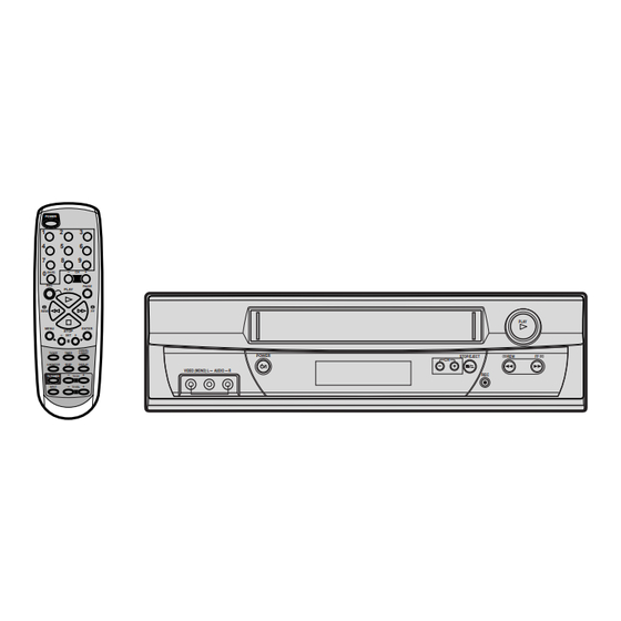
SERVICE MANUAL VIDEO CASSETTE RECORDER HR-J6009UM POWER (AUX) – PAUSE PLAY PLAY MENU ENTER STOP – CANCEL TV/VCR TIMER C.RESET POWER STOP/EJECT A.MONITOR SP/EP DISPLAY VIDEO (MONO) L – AUDIO – R – TV POWER TV CH – INPUT TV VOL... -
Page 3: Table Of Contents
TABLE OF CONTENTS Section Title Page Section Title Page Important Safety Precautions INSTRUCTIONS PLAYBACK PICTURE SHAKES ........1-31 DISASSEMBLY INSTRUCTION AUTO TRACKING DOES NOT OPERATE ....1-32 1.REMOVAL OF MECHANICAL PARTS AND WHEN PLAYBACK, FAST FORWARD OR REWIND MODE IS ACTIVATED, P.C.BOARDS .............. -
Page 4: Important Safety Precautions
Important Safety Precautions Prior to shipment from the factory, JVC products are strictly inspected to conform with the recognized product safety and electrical codes of the countries in which they are to be sold. However, in order to maintain such compliance, it is equally important to implement the following precautions when a set is being serviced. - Page 5 Safety Check after Servicing Examine the area surrounding the repaired location for damage or deterioration. Observe that screws, parts and wires have been returned to original positions, Afterwards, perform the following tests and confirm the specified values in order to verify compli- ance with safety standards.
-
Page 7: Disassembly Instruction
DISASSEMBLY INSTRUCTIONS 1-3: DECK CHASSIS (Refer to Fig. 1-3) REMOVAL OF MECHANICAL PARTS Remove the 3 screws 1. AND P.C. BOARDS Disconnect the following connectors: (CP1001, CP4001, 1-1: TOP CABINET AND FRONT CABINET CP4002 and CP4003). (Refer to Fig. 2-1) Remove the Deck Chassis in the direction of arrow. -
Page 8: Removal Of Deck Parts
DISASSEMBLY INSTRUCTIONS NOTE 2. REMOVAL OF DECK PARTS In case of the Locker R installation, check if the two 2-1: TOP BRACKET (Refer to Fig. 2-1) positions of Fig. 2-3-B are correctly locked. Extend the 2 supports 1. When you install the Cassette Side R, be sure to move Slide the 2 supports 2 and remove the Top Bracket. -
Page 9: Loading Motor/Worm
DISASSEMBLY INSTRUCTIONS 2-6: LOADING MOTOR/WORM (Refer to Fig. 2-6-A) Tension Arm Ass’y Remove the screw 1. Remove the Loading Motor. Remove the Worm. Fig. 2-7-A Loading Motor Tension Connect Tension Band Worm Main Chassis Tension Spring Tension Arm Ass’y Tension Holder •... -
Page 10: S Reel/T Reel/Idler Arm Ass'y/Idler Gear
DISASSEMBLY INSTRUCTIONS 2-8: T BRAKE ARM/T BRAKE BAND (Refer to Fig. 2-8-A) Remove the T Brake Spring. Idler Gear Turn the T Brake Arm clockwise and bend the hook section to remove it. Idler Arm Ass’y Unlock the 2 supports 1 and remove the T Brake Band. S Reel T Brake Band T Reel... -
Page 11: A/C Head
DISASSEMBLY INSTRUCTIONS 2-10: CASSETTE OPENER/PINCH ROLLER BLOCK/P5 ARM ASS’Y (Refer to Fig. 2-10-A) Unlock the support 1 and remove the Cassette Opener. Remove the Pinch Roller Block and P5 Arm Ass’y. Cassette Opener Spring Position Fig. 2-11-B Pinch Roller Block 2-12: FE HEAD (RECORDER ONLY) (Refer to Fig. -
Page 12: Capstan Dd Unit
DISASSEMBLY INSTRUCTIONS 2-14: CAPSTAN DD UNIT (Refer to Fig. 2-14-A) 2-15: MAIN CAM/PINCH ROLLER CAM/JOINT GEAR (Refer to Fig. 2-15-A) Remove the Capstan Belt. Remove the 3 screws 1. Remove the E-Ring 1, then remove the Main Cam. Remove the E-Ring 2, then remove the Pinch Roller Remove the Capstan DD Unit. -
Page 13: Clutch Ass'y/Ring Spring/ Clutch Lever/Clutch Gear
DISASSEMBLY INSTRUCTIONS NOTE 2-18: CASSETTE GUIDE POST/INCLINED BASE S/T UNIT/P4 CAP (Refer to Fig. 2-18-A) 1. When you install the Loading Arm S Unit, Loading Arm T Unit and Main Loading Gear, align each marker. (Refer to Remove the P4 Cap. Unlock the support 1 and remove the Cassette Guide Fig. -
Page 14: Removal And Installation Of Flat Package Ic
DISASSEMBLY INSTRUCTIONS 3. REMOVAL AND INSTALLATION OF FLAT 3. When IC starts moving back and forth easily after desoldering completely, pickup the corner of the IC using PACKAGE IC a tweezers and remove the IC by moving with the IC REMOVAL desoldering machine. -
Page 15: Installation
DISASSEMBLY INSTRUCTIONS INSTALLATION 4. When bridge-soldering between terminals and/or the soldering amount are not enough, resolder using a Thin- 1. Take care of the polarity of new IC and then install the tip Soldering Iron. (Refer to Fig. 3-8.) new IC fitting on the printed circuit pattern. Then solder each lead on the diagonal positions of IC temporarily. -
Page 16: Key To Abbreviations
KEY TO ABBREVIATIONS Audio/Control H.SW Head Switch Automatic Color Control Hertz Audio Erase Integrated Circuit Automatic Frequency Control Intermediate Frequency Automatic Fine Tuning Indicator AFT DET Automatic Fine Tuning Detect Inverter Automatic Gain Control Killer Amplifier Left Antenna Light Emitting Diode A.PB Audio Playback LIMIT AMP... - Page 17 KEY TO ABBREVIATIONS SYNC Synchronization SYNC SEP Sync Separator, Separation Transistor TRAC Tracking TRICK PB Trick Playback Test Point UNREG Unregulated Volt Voltage Controlled Oscillator Video Intermediate Frequency Vertical Pulse, Voltage Display V.PB Video Playback Variable Resistor V.REC Video Recording Visual Search Fast Forward Visual Search Rewind Voltage Super Source...
-
Page 18: Preventive Checks And Service Intervals
PREVENTIVE CHECKS AND SERVICE INTERVALS The following standard table depends on environmental conditions and usage. Parts replacing time does not mean the life span for individual parts. Also, long term storage or misuse may cause transformation and aging of rubber parts. The following list means standard hours, so the checking hours depends on the conditions. -
Page 19: Service Mode List
SERVICE MODE LIST This unit provided with the following SERVICE MODES so you can repair, examine and adjust easily. Method Operations Adjusting of the Tracking to the center position. Press the ATR button on the Refer to the “MECHANICAL ADJUSTMENT” (GUIDE ROLLER) and “ELECTRICAL remote control for more than ADJUSTMENT”... -
Page 20: Mechanical Adjustments
MECHANICAL ADJUSTMENTS TAPE REMOVAL METHOD AT NO POWER 1. CONFIRMATION AND ADJUSTMENT SUPPLY Read the following NOTES before starting work. 1. Remove the Top Cabinet and Front Cabinet. • Place an object which weighs between 450g~500g on the (Refer to item 1 of the DISASSEMBLY INSTRUCTIONS.) Cassette Tape to keep it steady when you want to make 2. -
Page 21: Confirmation Of Reel Brake Torque
MECHANICAL ADJUSTMENTS 1-4: CONFIRMATION OF REEL BRAKE TORQUE 2. CONFIRMATION AND ADJUSTMENT OF (S Reel Brake) (Refer to Fig. 1-4-B) TAPE RUNNING MECHANISM Once set to the Fast Forward mode then set to the Stop Tape Running Mechanism is adjusted precisely at the mode. -
Page 22: Audio/Control Head
MECHANICAL ADJUSTMENTS 2-2: CONFIRMATION AND ADJUSTMENT OF AUDIO/ 2-3: TAPE RUNNING ADJUSTMENT CONTROL HEAD (X VALUE ADJUSTMENT) When the Tape Running Mechanism does not work well, Confirm and adjust the position of the Tension Post. adjust the following items. (Refer to item 1-1) Adjust the Guide Roller. -
Page 23: Electrical Adjustments
ELECTRICAL ADJUSTMENTS Read and perform this adjustment when repairing the circuits or replacing electrical parts or PCB assemblies. 1. BASIC ADJUSTMENT CH-2 CAUTION When you exchange IC and Transistor for a heat sink, apply the silicon grease (YG6260M) on the contact section of the heat sink. -
Page 24: Ic Descriptions
IC DESCRIPTIONS SYSCON PCB OEC0115A (IC1001) PORT PIN NAME DESCRIPTION SEG8 LEM(LED Module) control terminal. AVSS AVSS Ground. P07/AN7 BOT-H Tape start sensor input signal. P06/AN6 HI-FI_ENV Input terminal of HiFi RF envelope. P05/AN5 PGMM Input voltage from Variable Resistor of PG SHIFTER. P04/AN4 MS_SEN-B Input terminal of mecha state sensor. - Page 25 IC DESCRIPTIONS SYSCON PCB OEC0115A (IC1001) PORT PIN NAME DESCRIPTION CTL_AMP CTL_AMP Output terminal for amp out. Input terminal for DRUM FG signal detection. Input terminal for DRUM PG signal derection. Input terminal for CAPSTAN FG signal detection. SV VDD VCC(SV) + 5V OSD VDD...
- Page 26 IC DESCRIPTIONS SYSCON PCB OEC0115A (IC1001) PORT PIN NAME DESCRIPTION GRID4 LEM(LED Module) control terminal. GRID3 LEM(LED Module) control terminal. GRID2 LEM(LED Module) control terminal. GRID1 LEM(LED Module) control terminal. TAB SW Input terminal for judge the tape if it has TAB or not. POWER_ON_L For control the user power switch ON/OFF.
-
Page 27: Servo Timing Chart
SERVO TIMING CHART SYSCON PCB IC1001 (OEC0115A) DPG 39 PIN DFG 38 PIN 24 Cycle CH 1 CH 2 H. SW. P 24 PIN V-SYNC (E-E) 54 PIN REC CTL (REC) 35 PIN V-SYNC (TRICK PB) 27 PIN • WAVEFORM CHANGES DEPENDED ON THE TAPE SPEED 1-21... -
Page 28: Mechanism Timing Chart
MECHANISM TIMING CHART Please see the list below for the operational timing and the mode sensor output of the main parts on each mechanism modes. MECHANISM MODE EJECT STBY UNLOAD STOP3 F.SLOW STOP2 FF/REW Mode Dealing Directions Revolutional Angle of 206.3 226.4 272.2... -
Page 29: Troubleshooting Guide
TROUBLESHOOTING GUIDE POWER DOES NOT TURN ON Is the voltage at pins Check IC1001. 15 and 22 of IC1001 about 5V? Check AT+5.2V line and the Is the voltage at cathode check peripheral circuit. of D512 about 5V? Check Around T501. 1-23... -
Page 30: Power Shuts Off
TROUBLESHOOTING GUIDE POWER SHUTS OFF Insert a cassette and push PLAY button. Check CAPSTAN DD UNIT and Does it Power off in about CYLINDER UNIT. 3 seconds? Check REEL SENSOR Does it Power off in about and CAPSTAN BELT. 6 seconds? Check REEL SENSOR and Does it Power off intermittently? CAPSTAN BELT slack. -
Page 31: Cylinder Not Rotating During Playback And Recodrding
TROUBLESHOOTING GUIDE CYLINDER NOT ROTATING DURING PLAYBACK AND RECORDING Is the voltage at pins Check pins 26, 38, 39 and 65 11 and 12 of CP1001 of IC1001 lines. about DC5V? In playback, is the voltage at pins 1, 4, 5 and 9 of CP1001 Replace CAPSTAN DD UNIT. -
Page 32: Ff/Rew Do Not Work
TROUBLESHOOTING GUIDE FF/REW DO NOT WORK Is the voltage changing at pin 82 of IC1001 when you Check pins 8 and 9 of IC1001 lines. press FF/REW? Check DECK MECHANISM. AUDIO SHAKES Is AUDIO HEAD scratched? Replace AUDIO HEAD. Does pin 40 of IC1001 Replace CAPSTAN DD. -
Page 33: Cassette Tape Is Not Accepted
TROUBLESHOOTING GUIDE CASSETTE TAPE IS NOT ACCEPTED Does WORM GEAR Check CASSETTE LOADING BLOCK. activate? When cassette is not Check LED and PHOTO SENSOR inserted, is the voltage at pin on DECK. 3 of IC1001 5V? When a cassette is inserted, is the voltage between Replace LOADING MOTOR. -
Page 34: When Inserting Cassette, It Ejects Immediately
TROUBLESHOOTING GUIDE WHEN INSERTING CASSETTE, IT EJECTS IMMEDIATELY Defective CASSETTE or Does Another cassette go down? CASSETTE LOADING BLOCK. Are SW1001 and the lever Check Rec LEVER. of the stage set correctly? After a CASSETTE is Check SW1001. inserted is the voltage at pin 80 of IC1001 LOW? Check IC1001. -
Page 35: Tape Loading Is Ok, But Unloads Immediately
TROUBLESHOOTING GUIDE TAPE LOADING IS OK, BUT UNLOADS IMMEDIATELY Is the voltage at pins 11 Check pins 26, 38, 39 Does CYLINDER rotate? and 12 of CP1001 UNREG and 65 of IC1001 lines. In playback, is the voltage Replace CAPSTAN DD UNIT. at pins 1,4,5 and 9 of CP1001 about 5V? Replace CYLINDER UNIT. -
Page 36: Capstan Dd Motor Not Rotating
TROUBLESHOOTING GUIDE CAPSTAN DD MOTOR NOT ROTATING In playback, is the voltage Check POWER circuit. at pin 1 of CP1001 12V? Is the voltage at pin 3 of CP1001 5V? In playback, check the Replace IC1001. voltage at pin 25 of IC1001 is 2.5V? Does DD MOTOR rotate now? If not, replace DD MOTOR . -
Page 37: Playback Picture Jitters Horizontally
TROUBLESHOOTING GUIDE PLAYBACK PICTURE JITTERS HORIZONTALLY Is FG Pulse output level Replace CYLINDER MOTOR. at pin 1 of CP1001 about 6V? Is the voltage at pin 83 of Replace IC1001. IC1001 about 5V? Replace CYLINDER MOTOR. PLAYBACK PICTURE SHAKES Is FG Pulse output level Replace CYLINDER MOTOR. -
Page 38: Auto Tracking Does Not Operate
TROUBLESHOOTING GUIDE AUTO TRACKING DOES NOT OPERATE By manual tracking, does the DC level at pin 59 Check CYLINDER UNIT. of IC4001 change? In auto tracking, is the Does the CTL PULSE voltage at pin 14 of IC1001 (about 1.0Vp-p) appear at pin 37 Check CONTROL HEAD. -
Page 39: Playback Picture Jitters Vertically
TROUBLESHOOTING GUIDE PLAYBACK PICTURE JITTERS VERTICALLY Does tracking noise appear in the picture? By adjusting the manual tracking UP/DOWN buttons, will the Check P/B ENVELOPE. noise disappear in the picture? Are GUIDE POSTS Adjust GUIDE POST height. the right height? Adjust PG SHIFTER. -
Page 40: No Playback Picture
TROUBLESHOOTING GUIDE NO PLAYBACK PICTURE Is the voltage at pins 44, Is E-E appearing on Check P.CON 5V line. 52 and 68 of IC4001 5V? the Monitor TV? Check IC4001. Is there Video signal Check J4203. at pin 30 of IC4001? Is there VIDEO signal Check IC4001 and the at pin 26 of IC4001? -
Page 41: No Picture During Playback
TROUBLESHOOTING GUIDE NO PICTURE DURING PLAYBACK Is there Video signal Check IC4001 and check the at pin 26 of IC4001? peripheral circuit. Is there Color signal Replace IC4001. in Video signal at pin 26 of IC4001? Check IC4001. NO COLOR DURING SELF RECORDING AND PLAYBACK Replace J4203. -
Page 42: Playback Picture Noisy(Even After Cleaning Heads)
TROUBLESHOOTING GUIDE PLAYBACK PICTURE NOISY (EVEN AFTER CLEANING HEADS) Is FM signal at TP4001 Check IC4001 and CYLINDER UNIT. more than 300mVp-p? Is VIDEO waveform at pin 30 of IC4001 2Vp-p Check IC4001 and peripheral circuit. are there any noises? Is video output at pin 26 of IC4001 2Vp-p and are Check IC4001 and IC1001. -
Page 43: No Normal Audio On Playback
TROUBLESHOOTING GUIDE NO NORMAL AUDIO ON PLAYBACK Does audio appear on E-E? Refer to section "NO E-E". Does AUDIO signal appear Check C4031 and peripheral circuit. at pin 6 of IC4001? Does AUDIO signal appear Check IC4001 and peripheral circuit. at pin 10 of IC4001? Check AUDIO HEAD for debris of stains. -
Page 44: Audio Can Not Be Recorded
TROUBLESHOOTING GUIDE AUDIO CAN NOT BE RECORDED Is BIAS level O.K at Is the voltage at Emitter Check POWER circuit. T4001? of Q4003 5V? Is the voltage at pin 23 Check IC4001. of IC4001 above 5V? T4001 is broken or shorted. Check the circuit between Is there AUDIO signal audio out of Tuner and... -
Page 45: Recording Mechanism Works, But No Video Recorded From Input Jack Or Tuner
TROUBLESHOOTING GUIDE RECORDING MECHANISM WORKS, BUT NO VIDEO RECORDED FROM INPUT JACK OR TUNER Check the circuit from Does VIDEO signal VIDEO input jack to IC4001, appear at pins 30 and from Tuner Pack to IC4001. 32 of IC4001? Is the voltage at pin Does VIDEO signal appear Check IC1001. -
Page 46: No E-E(No Video From Tuner)
TROUBLESHOOTING GUIDE NO E-E (NO VIDEO FROM TUNER) Are the plugs Disconnect the plugs from the connected to the VIDEO input Jacks. VIDEO input jacks? Do the voltages appear at each terminal +B(5V), Check peripheral circuit. PB(5V) and TU(32V) of TU6001? Check VIDEO Does VIDEO signal appear... -
Page 47: No E-E Audio(Mono)
TROUBLESHOOTING GUIDE NO E-E AUDIO (MONO) Is the voltage at pins 52, Check POWER BLOCK. 68 and 77 of IC4001 5V? Does signal appear Check J4204 and J4205. at pin 78 of IC4001? Does signal appear Replace IC4001. at pin 10 of IC4001? Check J4201. -
Page 48: No Tuner Audio(Mono)
TROUBLESHOOTING GUIDE NO TUNER AUDIO (MONO) Do the voltages appear at each terminal +B(5V), Check POWER BLOCK. PB(5V) and TU(32V) of TU6001? Check TU6001 and Does signal appear peripheral circuit. at pin 22 of TU6001? Does signal appear Replace IC4001. at pin 76 of IC4001? Check J4201 and peripheral circuit. -
Page 49: Reference
<Reference> GENERAL SPECIFICATIONS System VHS Player / Recorder System Video System NTSC Hi-Fi STEREO NTSC PB(PAL60Hz) Deck DECK OVD-7 Loading System Front Motor Heads Video Head 4Head FM Audio Head 2Head Normal Audio /Control Mono / Yes Erase(Full Track Erase) Tape Speed NTSC... - Page 50 <Reference> GENERAL SPECIFICATIONS On Screen Menu Display Menu Type Character Timer Rec Set Auto Repeat On/Off SAP On Off CH Set-Up TV/CATV Auto CH Memory Add/Delete Pin Code Registration System Set-Up Clock Set Yes (Calendar 12H) Language No Noise Back Ground G-CODE(or SHOWVIEW or PLUSCODE)No.
- Page 51 <Reference> GENERAL SPECIFICATIONS G-12 Remote Unit RC-ES Control Glow in Dark Remocon Format type Custom Code 43 / 03 Power Source Voltage(D.C) UM size x pcs UM-4 x 2 pcs Total Keys 35 Keys Keys Power 0/Input Select CH Up CH Down Input Select Play/Slow...
- Page 52 <Reference> GENERAL SPECIFICATIONS G-13 Features Auto Head Cleaning Auto Tracking Index Search HQ (VHS Standard High Quality) Auto Power On, Auto Play, Auto Rewind, Auto Eject Auto Power Off Forward/Reverse Picture Search VIDEO PLUS+(SHOWVIEW,G-CODE) One Touch Playback Picture Control Auto CH Memory Channel Lock Hotel Lock Anti Theft...
- Page 53 <Reference> GENERAL SPECIFICATIONS G-15 Interface Switch Front Power Play Pause/Still System Select One Touch Playback Channel Up Channel Down F.FWD/Cue Eject/Stop Main Power SW Volume Up Volume Down Rew/Rev Rec/OTR Rear RF Output SW Indicator Power Stand by Repeat TV/VCR T-Rec Tape In Terminals...
- Page 56 VICTOR COMPANY OF JAPAN, LIMITED S40894 VIDEO DIVISION Printed in Japan...