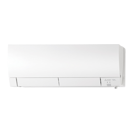
Mitsubishi Electric MSZ-FH25VE Installation Manual
Hide thumbs
Also See for MSZ-FH25VE:
- Operating instructions manual (16 pages) ,
- Installation manual (4 pages) ,
- Service manual (42 pages)
Advertisement
Quick Links
Download this manual
See also:
Service Manual
INSTALLATION MANUAL
1. BEFORE INSTALLATION
1-1. THE FOLLOWING SHOULD ALWAYS BE OBSERVED FOR SAFETY
■ Do not install the unit by yourself (user).
■ Perform the installation securely referring to the installa-
tion manual.
■ When installing the unit, use appropriate protective equip-
ment and tools for safety.
■ Install the unit securely in a place which can bear the
weight of the unit.
■
rienced electrician, according to the installation manual.
electrical appliances to the circuit.
■ Earth the unit correctly.
Do not connect the earth to a gas pipe, water pipe, lightning rod, or
■
with parts or screws.
■ Be sure to cut off the main power in case of setting up the
indoor P.C. board or wiring works.
■
block connecting sections so the stress of the wires is
use intermediate connection.
■ Install an earth leakage breaker depending on the instal-
lation place.
■ Perform the drainage/piping work securely according to
the installation manual.
1-2. SELECTING THE INSTALLATION LOCATION
INDOOR UNIT
REMOTE CONTROLLER
a pillar or wall and install wireless remote controller.
1-3. SPECIFICATIONS
Outdoor unit
power switch is shut off, it must interrupt all phases.)
Model names are indicated in 1-3.
installation manual of the multi unit for
outdoor unit installation.
WARNING
■
may leak.
■ Do not use intermediate connection of the power cord or
one AC outlet.
etc.
■
the installation work.
■ When plugging the power supply plug into the outlet,
-
make sure that there is no dust, clogging, or loose parts
in both the outlet and the plug. Make sure that the power
supply plug is pushed completely into the outlet.
■ Attach the electrical cover to the indoor unit and the
service panel to the outdoor unit securely.
■ When installing, relocating, or servicing the unit, make
(R410A) enters the refrigerant circuit.
CAUTION
■
outdoor unit.
Note:
received.
OUTDOOR UNIT
hot air.
-
the unit legs.
2
1.0 mm
2
1.5 mm
2.0 mm
2
ing.
-
Required Tools for Installation
Phillips screwdriver
Scale
65 mm hole saw
■ Do not discharge the refrigerant into the atmosphere. If
refrigerant leaks during installation, ventilate the room.
■ Check that the refrigerant gas does not leak after instal-
lation has been completed.
-
■ Use appropriate tools and piping materials for installation.
appropriate tools or materials and incomplete installation could
■ When pumping down the refrigerant, stop the compressor
before disconnecting the refrigerant pipes.
■ When installing the unit, securely connect the refrigerant
pipes before starting the compressor.
■
this manual.
■ The unit shall be installed in accordance with national
wiring regulations.
■ Do not install the outdoor unit where small animals may
live.
Note:
Note:
its air inlet side facing the wall.
sewage, waste water.
Pipe size
connecting wire
4-core
1.0 mm
2
-
Pipe cutter with reamer
Pipe length and height difference
10
8 mm
-
-
-
Advertisement

Summary of Contents for Mitsubishi Electric MSZ-FH25VE
-
Page 1: Installation Manual
Required Tools for Installation Phillips screwdriver Scale Model names are indicated in 1-3. 65 mm hole saw installation manual of the multi unit for Pipe cutter with reamer INSTALLATION MANUAL outdoor unit installation. 1. BEFORE INSTALLATION 1-1. THE FOLLOWING SHOULD ALWAYS BE OBSERVED FOR SAFETY WARNING ■... -
Page 2: Installation Diagram
1-4. INSTALLATION DIAGRAM Be sure to use wall hole ACCESSORIES Seal the wall hole gap metal parts in the wall rodents in case the wall 4 × 25 mm is hollow. × 16 mm Outdoor unit installation Felt tape that there is no gap. 500 mm attached to a wall containing treated wooden piece 20 mm... -
Page 3: Outdoor Unit Installation
Left or left-rear piping Rear, right, or downward piping Note: 1) Put the refrigerant piping and the drain hose right piping. Be sure to reattach the drain hose and the drain cap in case the end. piping. of left or left-rear piping. Drain cap downward piping. -
Page 4: Relocation And Maintenance
4. PURGING PROCEDURES, LEAK TEST, AND TEST RUN 4-1. PURGING PROCEDURES AND LEAK TEST operating instructions for details. gas pipe side of the outdoor unit. Checking the remote (infrared) signal reception Stop valve cap Pressure gauge Stop valve 4-3. AUTO RESTART FUNCTION for details.) Stop valve for Caution:...


