Table of Contents
Advertisement
Quick Links
1
SERVICE MANUAL
Level 1&2
RM-529 / RM-530
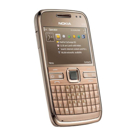
Transceiver characteristics
Band:
GSM/EDGE 850/900/1800/1900
WCDMA/HSDPA/HSUPA 850/1900/2100 or
900/1900/2100
Main display:
320 x 240 QVGA 2.36" 16million colors, TFT active
matrix
Camera:
5 Mpix digital camera with 5 x zoom
Operating System:
S60 3
rd
Symbian OS9.3
Connections:
WLAN, Bluetooth 2.0 EDR, 3.5 mm Nokia Audio
connecor, High-Speed 2.0 Micro-USB, Micro SD card
(4GB in sales package)
Transceiver with - battery pack
Talk time
GSM:
12 h 30 min
Note:
Talk times are dependant on network parameters and
phone settings
Confidential Copyright © 2009 NOKIA All rights reserved
Nokia E72 RM-529 / RM-530
Service Manual Level 1&2
Edition Feature Pack 2 (S60 3.2.3)
Standby
GSM:
492 h
Version 1.0
ISSUE 1
Advertisement
Table of Contents

Related Manuals for Nokia E72 RM-529


Summary of Contents for Nokia E72 RM-529
- Page 1 Transceiver with - battery pack Talk time Standby GSM: GSM: 12 h 30 min 492 h Note: Talk times are dependant on network parameters and phone settings Confidential Copyright © 2009 NOKIA All rights reserved Version 1.0 ISSUE 1...
-
Page 2: Table Of Contents
6. Battery information ..................................8 7. Exploded view ....................................9 8. Service devices .....................................10 9. SW-update .....................................11 10. Disassembly instructions ..............................12 11. Assembly hints ..................................19 12. Solder components ................................20 Confidential Copyright © 2009 NOKIA All rights reserved Version 1.0 ISSUE 1... -
Page 3: Change History
Approved 31.8.2009 The purpose of this document is to help NOKIA service levels 1 and 2 workshop technicians to carry out service to NOKIA products. This Service Manual is to be used only by authorized NOKIA service suppliers, and the content of it is confidential. Please note that NOKIA provides also other guidance documents (e.g. -
Page 4: Copyright
Nokia operates a policy of continuous development. Nokia reserves the right to make changes and improvements to any of the products described in this document without prior notice. Under no circumstances shall Nokia be responsible for any loss of data or income or any special, incidental, consequential or indirect damages howsoever caused. -
Page 5: Warnings And Cautions
3. Use only approved components as specified in the parts list. 4. Ensure all components, modules screws and insulators are correctly re–fitted after servicing and alignment. 5. Ensure all cables and wires are repositioned correctly Confidential Copyright © 2009 NOKIA All rights reserved Version 1.0 ISSUE 1... -
Page 6: Esd Protection
Nokia E72 RM-529 / RM-530 Service Manual Level 1&2 4. ESD PROTECTION Nokia requires that service points have sufficient ESD protection (against static electricity) when servicing the phone. Any product of which the covers are removed must be handled with ESD protection. -
Page 7: Care And Maintenance
All of the above suggestions apply equally to the product, battery, charger or any accessory. Confidential Copyright © 2009 NOKIA All rights reserved Version 1.0 ISSUE 1... -
Page 8: Battery Information
Batteries’ performance is particularly limited in temperatures well below freezing. Do not dispose batteries in a fire! Dispose of batteries according to local regulations (e.g. recycling). Do not dispose as household waste. Confidential Copyright © 2009 NOKIA All rights reserved Version 1.0 ISSUE 1... -
Page 9: Exploded View
USB DOOR SD DOOR I0015 I0016 SCREW 1.8x5.0 I0027 BATTERY COVER I0028 Only available as These parts can not be Ver. 1.0 assembly reused after removal Confidential Copyright © 2009 NOKIA All rights reserved Version 1.0 ISSUE 1... -
Page 10: Service Devices
Service Bulletin (SB-011) on NOKIA BL-4S Battery Online. Supplier or manufacturer contacts for tool re-order can be found in “Recommended service equipment” document on NOKIA Online. Confidential Copyright © 2009 NOKIA All rights reserved Version 1.0 ISSUE 1... -
Page 11: Sw-Update
To use the FLS-5 Flash Dongle, follow the user guide inside the sales package. Please check always for the latest version of flash software, wich is available on Nokia Online. Confidential Copyright © 2009 NOKIA All rights reserved Version 1.0... -
Page 12: Disassembly Instructions
6) Using the same procedure release also the clip on and the B-COVER ASSEMBLY. Slide it from top to opposite side of the A-COVER. bottom to release the clip holding the A-COVER ASSEMBLY. Confidential Copyright © 2009 NOKIA All rights reserved Version 1.0 ISSUE 1... - Page 13 11) Protect the LCD with protective film. 12) Open the LCD connector with the SS-93. Be careful not to damage the connector or the components nearby! Confidential Copyright © 2009 NOKIA All rights reserved Version 1.0 ISSUE 1...
- Page 14 17) Carefully press with fingers through the UI 18) Remove the LCD. SHIELD ASSY opening so that the LCD releases. Confidential Copyright © 2009 NOKIA All rights reserved Version 1.0 ISSUE 1...
- Page 15 SS-210, otherwise socket locking pins are damaged when metal plates are pressed down. B) Press metal sheets down, as shown in small picture. Confidential Copyright © 2009 NOKIA All rights reserved Version 1.0 ISSUE 1...
- Page 16 29) Lever out the DC JACK with the dental tool and 30) Lift up the ANTENNA ASSEMBLY with the dental remove it with tweezers. Discard it. tool and remove it. Confidential Copyright © 2009 NOKIA All rights reserved Version 1.0 ISSUE 1...
- Page 17 35) To release the GPS BT WLAN ANTENNA first lever 36) … and then remove it with tweezers. it out with the dental tool as shown … Confidential Copyright © 2009 NOKIA All rights reserved Version 1.0 ISSUE 1...
- Page 18 37) Finally rotate the SD CARD DOOR to vertical 38) Nokia E72 disassembly is now complete. position and pull the holder through the small opening. -END OF DISASSEMBLY- Confidential Copyright © 2009 NOKIA All rights reserved Version 1.0 ISSUE 1...
-
Page 19: Assembly Hints
2) Tighten the four TORX + size 6 screws to the torque of 12 Ncm in the order shown. torque of 25 Ncm in the order shown. Confidential Copyright © 2009 NOKIA All rights reserved Version 1.0 ISSUE 1... -
Page 20: Solder Components
Nokia E72 RM-529 / RM-530 Service Manual Level 1&2 12. SOLDER COMPONENTS X2401 X2450 F2000 X1501 X7550 F3300 F1400 S2400 X1500 G2200 X7551 Ver. 1.0 Confidential Copyright © 2009 NOKIA All rights reserved Version 1.0 ISSUE 1...