Sign In
Upload
Manuals
Brands
ABB Manuals
DC Drives
ACS1000i air-cooled
ABB ACS1000i air-cooled Manuals
Manuals and User Guides for ABB ACS1000i air-cooled. We have
2
ABB ACS1000i air-cooled manuals available for free PDF download: User Manual
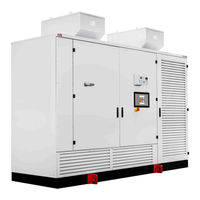
ABB ACS1000i air-cooled User Manual (156 pages)
Brand:
ABB
| Category:
Industrial Equipment
| Size: 7.58 MB
Table of Contents
Table of Contents
3
About this Manual
13
Equipment Covered by this Manual
13
Structure of the User Documentation
13
Terms and Definitions
14
Table 1-1 Terms and Definitions
14
Related Documents
16
Table 1-2 Maintenance
16
Table 1-3 Technical Data
16
Table 1-4 Schematics
16
Table 1-5 Specifications and Guidelines
16
Table 1-6 Serial Communication Interfaces
16
Table 1-7 Encoder
16
Target Groups and Required Qualification
17
Handling
17
Mechanical Installation
17
Electrical Installation
17
Operation
17
Maintenance
18
User's Responsibilities
18
Intended Use of Equipment
18
Quality Certificates and Applicable Standards
19
Table 1-8 Standards
19
Items Covered by Delivery
20
Identifying the Delivery
20
Figure 1-1 Delivered Items
20
Important Safety Information
21
Safety Standards
21
Safety Messages
21
Product Safety Labels
22
Figure 2-1 Product Warning Label Examples (Label Placement Depends on the Drive)
22
General Safety Instructions
23
The 7 Steps that Save Lives
24
Possible Residual Risks
26
Main Circuit Breaker Protection Device
27
Figure 2-2 Drive System Overview
27
Safety and Protection Requirements
28
Minimum Requirements for MCB and MCB Control
28
Figure 2-3 MCB Opening Timing Diagram
29
Maintenance Recommendation
30
Power Electronics and Cabinet Features
31
Overview
31
Figure 3-1 Acs1000I Air-Cooled
31
Main Components of the Drive System
32
Figure 3-2 Block Diagrams of the Drive
32
Power Supply Configurations
33
Main Power Supply Configurations
33
Figure 3-3 Drive Overview with Power Supplies
33
Auxiliary Power Supply Configurations
34
Drive Topology
35
Overview
35
Figure 3-4 Acs1000I Air-Cooled with Combined Input Disconnector and Grounding Switch
35
Figure 3-5 Acs1000I Air-Cooled with Grounding Switch
36
Terminal Compartment
37
Figure 3-6 Terminal Compartment with Input Disconnector (A) and Without Input Disconnector (B)
37
Control Compartment and Terminal Compartment
38
Figure 3-7 Control Compartment with Open Door
38
Transformer and Rectifier Compartment
39
Rectifier
39
Figure 3-8 Transformer and Rectifier Compartment with Combined Input Disconnector (A) and with Grounding Switch (B)
39
Grounding Switch
40
Figure 3-9 Switchgear of the Drive
40
Figure 3-10 Grounding Switch Unlocked Lamp (1)
41
Figure 3-11 Grounding the Drive
41
Trapped Key Interlock (Option)
42
Protection Igcts
42
Figure 3-12 Trapped Key Interlocking System (1)
42
Inverter
43
Filter
43
Figure 3-13 Three-Level Voltage Source Inverter Principle
43
Figure 3-14 Voltage and Current Waveforms at Drive Output
43
Cooling System
44
Figure 3-15 Fan Configurations and Air Flow
44
Figure 3-16 Fan Groups - AC and EC Fans
45
Figure 3-17 Fan Groups - EC Fans Only
45
Figure 3-18 Operating Times of the AC Fan Units During Continuous Drive Operation (A) and Intermittent Drive Operation (B)
46
Figure 3-19 Operating Principles of Redundant EC Fans
47
Optional Braking Chopper
48
Figure 3-20 Acs1000I with Braking Chopper (1)
48
Figure 3-21 Principle Diagram
48
Figure 3-22 Braking Chopper Design
49
Table 3-1 Braking Ratings
50
Cabinet Design
51
Mechanical Design
51
Additional Cabinets
52
Figure 3-23 Acs1000I with an Additional Cabinet (1)
52
Door Locking System
53
Optional Cabinets
53
Figure 3-24 Door Locks
53
Arc Resistant Design (Optional)
54
Internal Arc Classification
54
Figure 3-25 IAC Label Example
54
Table 3-2 ABB Arc Resistant Classes
54
Power Compartment Doors
55
Associated Protection Requirement
55
Figure 3-26 Door Bolts
55
Space Heaters
56
Figure 3-27 Optional Space Heaters
56
Control System
57
Overview
57
Figure 4-1 Block Diagram of Control System with Customer Interface (A), Control System (B) and Power Electronics (C)
57
Main Components
58
Local Control Panel
58
Figure 4-2 Control Compartment
58
AMC Circuit Board
59
Figure 4-3 AMC Circuit Board
59
Figure 4-4 Direct Torque Control
60
Figure 4-5 PID Control Mode
62
I/O Interfaces
63
IOEC I/O Modules
63
Figure 4-6 IOEC Interfaces Overview
63
Table 4-1 IOEC Module Configuration - Analog Inputs
64
Table 4-2 IOEC Module Configuration - Analog Outputs
64
Table 4-3 IOEC Module Configuration - Digital Inputs
64
Table 4-5 24 V Internal Voltage Supply
65
Table 4-4 IOEC Module Configuration - Digital Inputs
65
Figure 4-7 IOEC Module
66
Figure 4-8 IOEC Module Identification
67
Table 4-6 IOEC Module Identification
67
Serial Communication Interface (Fieldbus)
68
Pulse Encoder Interface NTAC (Option)
68
Figure 4-9 NTAC-02 Pulse Encoder Interface
68
Transportation, Storage and Disposal
69
Safety
69
Transport Conditions
69
Unpacking and Inspection
69
Lifting and Transportation
69
General Notes on Transportation
70
Using a Crane
70
Figure 5-1 Transporting the Cabinet by Crane (Lift Spreader Example)
71
Using Rollers
72
Figure 5-2 Moving the Drive with Rollers
72
Figure 5-3 Moving the Drive Backwards or Forwards
72
Storage
73
Storage Conditions
73
Storing the Drive
73
Storage and Handling of Spare Parts
74
Disposal of Packaging Materials and Components
74
Mechanical Installation
75
Safety
75
Overview of Installation Work
75
General Notes on Installation
75
Dimensions and Clearances
75
Cabinet Roof
75
Fire Protection
75
Cable Duct Material
75
Preparing the Floor
76
Fixing the Cabinet to the Floor
76
Figure 6-1 Position of Mounting Holes
76
Figure 6-2 Leveling the Drive
76
Installing the Fans
77
Figure 6-3 Fixing the Cabinet to the Floor
77
Figure 6-4 Cutouts in Drive Roof - Back (A) and Front (B)
77
Figure 6-5 Standard Fan Installation
78
Table 6-1 Fan Configurations
78
Figure 6-6 Lifting Point Locations on Fan Unit
79
Figure 6-7 Large Fan Installation
80
Figure 6-8 Small Fan Installation over a Roof Cutout for a Large Fan
81
Figure 6-9 Fan Installation Material
81
Additional Cabinet Compartments
82
Figure 6-10 Bolt Location at the Back of a Fan Unit
82
Electrical Installation
83
Safety
83
Overview of Installation Work
83
Cable Requirements
83
Ground Cable Connection and Cable Shield Connections
84
Figure 7-1 Grounding the Drive System
84
Power Cables, Ground Cables and Equipotential Bonding Conductor
85
Safety
85
Determining the Cable Length
85
MV Cable Entry from Top
86
Figure 7-2 Top Cable Entry - Installation Material
86
Figure 7-3 Bolt Locations for Cable Entry Box on Terminal Compartment Roof (a Is the Back and B Is the Front of the Compartment)
87
Figure 7-4 Insulating Barrier Placement for Top Cable Entry
88
MV Cable Entry from Bottom
89
Figure 7-5 Bottom Cable Entry - Installation Material
89
Figure 7-6 Bolt Locations on Terminal Compartment Roof for the Galvanized Steel Plate
90
Figure 7-7 Bracket Location on Insulating Barrier
91
Figure 7-8 Insulating Barrier Placement for Bottom Cable Entry
91
Connecting the Cables
92
Figure 7-9 Power Cable Terminals in a Terminal Compartment Without an Input Disconnector (A) and a Terminal Compartment with an Input Disconnector (B)
92
Figure 7-10 Bolted Busbar Connections
93
Auxiliary Power, Control and Serial Communication Cables
94
Preparing the Cable Entry and the Cables
94
Figure 7-11 Cable Entry from Top (A), from Bottom (B)
94
Preparing Cables for Cable Entries with Cable Glands
95
Figure 7-12 Top Entry for Auxiliary Power and Control Cables
95
Figure 7-13 Preparing Control Cables for Cable Glands
95
Connecting Additional Cabinets
96
Final Checks
96
Figure 7-14 Shield Grounding Point for Encoder Cable
96
Commissioning
97
Overview
97
Required Qualification
97
Commissioning Procedure
97
Commissioning Checklist
97
Customer Assistance
97
Customer Acceptance
97
Commissioning Checklists
98
Mechanical Installation Checklist
98
Electrical Installation Checklist
98
Main Circuit Breaker (MCB) Checklist
99
Motor Checklist
99
Insulation Tests Checklist
99
Power Supply Checklist
99
Miscellaneous Checklist
100
Operation
101
Safety
101
Overview
101
Operating Conditions
101
Local Operator Panel
101
Figure 9-1 Local Operator Panel
102
Status Messages
103
Start Sequence of the Drive
104
Stop Sequence of the Drive
105
Emergency off Sequence of the Drive
106
Starting the Drive
106
Checks before Starting the Drive
106
Starting the Drive Remotely
107
Starting the Drive Locally
107
Stopping the Drive
109
Emergency-Off
109
Initiating an Emergency-Off
110
Starting the Drive after an Emergency-Off
110
CDP Control Panel
111
Overview
111
Figure 10-1 CDP Control Panel
111
CDP Control Panel Functions
112
CDP Control Panel Modes
112
Identification Mode
112
Actual Signals Mode
113
Figure 10-2 Control Panel - Actual Signals Mode
115
Parameters Mode
120
Table 10-1 Parameter Groups
120
Figure 10-3 Control Panel - Parameters Mode
122
Figure 10-4 Control Panel - Functions Mode
126
Local and Remote Control
128
Local Control
128
Remote Control
128
Operational Commands
129
Setting the Direction of Rotation
129
Entering a Reference Value
131
Preventive and Corrective Maintenance
133
General Information
133
Required Qualification
133
Maintenance Schedule
133
Logbook
133
Spare Parts
133
Identifying Electrical Equipment
134
Device Identification
134
Cables and Wires
134
Understanding Wiring Diagrams
134
Figure 11-1 Device Identification
134
Alarm / Fault Indications
135
Messages
135
Error Message Levels
135
Fault Handling
136
Standard Troubleshooting Procedure
137
Removing the CDP Control Panel
138
Leds and Switches on Circuit Boards
139
AMC Circuit Board
139
Figure 11-2 AMC Circuit Board
139
IOEC I/O Modules
140
Figure 11-3 IOEC Module
140
Corrective Maintenance
141
Safety
141
Energizing the Drive Locally
142
Grounding
143
Grounding Switch Is Not Released
144
Figure 11-4 Location of I/O Modules and Fuses
144
Checking the Release Conditions for the Grounding Switch
145
Visual Checks on the Drive
147
Cleaning the Drive
147
Checking Wire and Cable Connections
148
Cleaning and Replacing Filter Mats
148
Table 11-1 Filter Mat Specifications
148
Figure 11-5 Cleaning and Replacing Filter Mats N
149
Inspecting and Replacing Batteries
150
Figure 11-6 Control Compartment - Battery Location
150
Figure 11-7 Control Compartment - Replacing the Batteries
151
Replacing a Fan Unit
152
Figure 11-8 Lifting Point Locations on Fan Unit
153
Advertisement
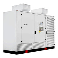
ABB ACS1000i air-cooled User Manual (174 pages)
MEDIUM VOLTAGE AC DRIVES
Brand:
ABB
| Category:
DC Drives
| Size: 13.39 MB
Table of Contents
01 About this Manual
6
Table of Contents
6
Copyright Notice
7
Equipment Covered by this Manual
7
Structure of the User Documentation
7
Terms and Abbreviations
8
Trademarks
9
Related Documentation
9
Target Groups and Required Qualification
10
Handling
11
Mechanical Installation
11
Electrical Installation
11
Operation
11
Maintenance
11
User's Responsibilities
11
Intended Use of Equipment
12
Cyber Security Disclaimer
12
Quality Certificates and Applicable Standards
13
Items Covered by Delivery
14
Identifying the Delivery
15
02 Important Safety Information
18
Damage Prevention Information
19
Overview
19
Safety Messages
19
Safety Standards
19
Product Safety Labels
20
General Safety Instructions
21
The 7 Steps that Save Lives
22
Possible Residual Risks
24
Important Note - Main Circuit Breaker
25
Minimum Requirements for MCB and MCB Control
26
Safety and Protection Requirements
26
Maintenance Recommendation
27
03 Power Electronics and Cabinet Features
30
Overview
32
Main Components of the Drive System
33
Power Supply Configurations
34
Main Power Supply Configurations
35
Auxiliary Power Supply Configurations
35
Drive Topology
36
Overview
36
Terminal Compartment
38
Control Compartment and Terminal Compartment
39
Transformer and Rectifier Compartment
40
Rectifier
40
Grounding Switch
41
Trapped Key Interlock (Option)
43
Protection Igcts
43
Inverter
44
Filter
44
Cooling System
45
Optional Braking Chopper
49
Cabinet Design
52
Mechanical Design
52
Additional Cabinets
52
Door Locking System
54
Additional Cabinets
54
Arc Resistant Design (Optional)
55
Internal Arc Classification
55
Power Compartment Doors
55
Associated Protection Requirement
56
Space Heaters
56
04 Control System
58
Overview
59
Main Components
60
Local Control Panel
61
AMC Circuit Board
61
I/O Interfaces
66
IOEC I/O Modules
66
Serial Communication Interface (Fieldbus)
70
Pulse Encoder Interface NTAC (Option)
70
05 Transportation, Storage and Disposal
72
Safety
73
Unpacking and Inspection
73
Lifting and Transportation
73
General Notes on Transportation
73
Using a Crane
74
Using Rollers
75
Transport Conditions
73
Storage
76
Storage Conditions
76
Storing the Drive
76
Storage and Handling of Spare Parts
77
Disposal of Packaging Materials and Components
77
07 Electrical Installation
90
Overview of Installation Work
91
Safety
91
Cable Requirements
91
Ground Cable Connection and Cable Shield Connections
91
Power Cables, Ground Cables and Equipotential Bonding Conductor
93
Safety
93
Determining the Cable Length
93
MV Cable Entry from Top
94
MV Cable Entry from Bottom
97
Connecting the Cables
99
Auxiliary Power, Control and Serial Communication Cables
102
Preparing the Cable Entry and the Cables
102
Preparing Cables for Cable Entries with Cable Glands
103
Connecting the Cables
104
Connecting Additional Cabinets
104
Final Checks
104
09 Operation
112
Overview
113
Overview of Local Operator Panel
113
Operating Conditions
113
Safety
113
Status Messages
115
Start Sequence of the Drive
116
Stop Sequence of the Drive
117
Emergency-Off Sequence of the Drive
118
Starting the Drive
119
Checks before Starting the Drive
119
Starting the Drive Remotely
119
Starting the Drive Locally
119
Stopping the Drive
122
Emergency-Off
123
Initiating an Emergency-Off
123
Starting the Drive after an Emergency-Off
124
10 CDP Control Panel
126
Overview
127
CDP Control Panel Functions
128
CDP Control Panel Modes
128
Identification Mode
128
Actual Signals Mode
130
Parameters Mode
137
Functions Mode
142
Local and Remote Control
144
Local Control
144
Remote Control
145
Operational Commands
146
Setting the Direction of Rotation
146
Entering a Reference Value
147
11 Preventive and Corrective
150
General Information
152
Required Qualification
152
Maintenance Schedule
152
Logbook
152
Spare Parts
152
Identifying Electrical Equipment
153
Device Identification
153
Cables and Wires
153
Understanding Wiring Diagrams
153
Alarm / Fault Indications
154
Messages
154
Error Message Levels
154
Fault Handling
154
Standard Troubleshooting Procedure
155
Removing the CDP Control Panel
156
Leds and Switches on Circuit Boards
157
AMC Circuit Board
157
IOEC I/O Modules
158
Corrective Maintenance
159
Safety
159
Energizing the Drive Locally
160
Grounding
162
Grounding Switch Is Not Released
162
Checking the Release Conditions for the Grounding Switch
164
Visual Checks on the Drive
166
Cleaning the Drive
166
Checking Wire and Cable Connections
167
Cleaning and Replacing Filter Mats
167
11.6.10 Inspecting and Replacing Batteries
169
11.6.11 Replacing a Fan Unit
171
Advertisement
Related Products
ABB ACS1000
ABB ACS1012-A1
ABB ACS 1013-A1
ABB ACS 1013-A2
ABB ACS1012-A3
ABB ACS1012-W1
ABB ACS 1014-W1
ABB ACS1012-W2
ABB ACS 1014-W3
ABB ACS104
ABB Categories
Industrial Equipment
Controller
Measuring Instruments
Battery Charger
DC Drives
More ABB Manuals
Login
Sign In
OR
Sign in with Facebook
Sign in with Google
Upload manual
Upload from disk
Upload from URL