Sign In
Upload
Manuals
Brands
ABB Manuals
DC Drives
ACS880-607LC
ABB ACS880-607LC Manuals
Manuals and User Guides for ABB ACS880-607LC. We have
3
ABB ACS880-607LC manuals available for free PDF download: Hardware Manual
ABB ACS880-607LC Hardware Manual (120 pages)
3-Phase dynamic brake units
Brand:
ABB
| Category:
Industrial Equipment
| Size: 7.61 MB
Table of Contents
Table of Contents
5
Introduction to the Manual
11
Contents of this Chapter
11
Applicability
11
Safety Instructions
11
Target Audience
11
Categorization by Frame Size and Option Code
12
Use of Component Designations
12
Quick Installation Flowchart
12
Related Documents
13
Terms and Abbreviations
14
Operation Principle and Hardware Description
15
Contents of this Chapter
15
Product Overview
15
Operation Principle
15
When Is Resistor Braking Necessary
15
Overview Diagram of the Drive System
16
Overview Drawing of the Drive System
17
Layout Drawings - Brake Module Cubicle
18
Layout Drawing - Brake Module R8I
21
Module Layout
21
Coolant Connectors
21
Connectors X50
22
Fiber Optic Connectors
23
Leds
23
Overview of Power and Control Connections
24
Brake Unit Control Devices
25
Overview of the Control Connections of the BCU Control Unit
25
The Control Panel
26
Control by PC Tools
26
Fieldbus Control
26
DC Switch and Charging Switch
26
Type Designation Labels
27
Type Designation Label of the Brake Unit
27
Type Designation Key
28
Basic Code
28
Option Codes
28
Guidelines for Planning the Electrical Installation
31
Contents of this Chapter
31
Limitation of Liability
31
North America
31
Generic Guidelines
31
Selecting the Brake Resistor
32
Selecting and Routing the Brake Resistor Cables
32
Resistor Cable Sizes and Length
32
Minimizing Electromagnetic Interference
32
Selecting the Installation Location for the Brake Resistors
33
Selecting the Resistor Thermal Switch Circuit Cable
33
Protecting the System against Thermal Overload
33
Protecting the System against Short-Circuits
33
Electrical Installation
35
Contents of this Chapter
35
Electrical Safety Precautions
35
General Notes
37
Printed Circuit Boards
37
Handling Fiber Optic Cables
37
Measuring the Insulation Resistance of the Brake Resistor Circuit
38
Connecting the Brake Resistor Cables and Thermal Switch
39
Connection Diagram
39
Connection Procedure of the Resistor Cables
40
Removing Shrouds
40
Connecting the Cables
40
Installing Shrouds
42
Use of Fasteners in Cable Lug Connections
43
Connection Procedure of the Thermal Switch Cable
44
Connecting the Control Cables
45
Control Cable Connection Procedure
45
Grounding the Outer Shields of the Control Cables 360° at the Cabinet Entry
45
Routing the Control Cables Inside the Cabinet
47
Connecting Control Cabling
47
Connecting a PC
49
The Control Unit
51
Contents of this Chapter
51
General
51
BCU-X2 Layout
52
Default I/O Diagram of the Brake Control Unit
54
Additional Information on the Connections
57
Power Supply for the Control Unit (XPOW)
57
The X485 Connector
57
Safe Torque off (XSTO, XSTO OUT)
57
FSO Safety Functions Module Connection (X12)
57
SDHC Memory Card Slot
57
Connector Data
58
BCU-X2 Ground Isolation Diagram
61
Installation Checklist
63
Contents of this Chapter
63
Checklist
63
Start-Up
65
Contents of this Chapter
65
Start-Up Procedure
66
Operating Instructions
69
Contents of this Chapter
69
Disconnecting the Brake Unit from the Drive DC Bus
69
Connecting the Brake Unit to the Drive DC Bus
69
Fault Tracing
71
Contents of this Chapter
71
Leds
71
Control Panel and Panel Platform/Holder Leds
71
Control Unit Leds
72
R8I Module Leds
72
7-Segment Display of the Brake Control Unit
72
Warning and Fault Messages
72
Maintenance
73
Contents of this Chapter
73
Maintenance Intervals
73
Description of Symbols
73
Recommended Maintenance Intervals after Start-Up
73
Maintenance Timers and Counters
75
Cabinet
75
Cleaning the Interior of the Cabinet
75
Cleaning the Exterior of the Drive
76
Fan Replacement
77
Brake Chopper Module Cubicle
77
Fan in the Output Cubicle, Top Cable Entry (Option +H351)
78
Brake Module
79
Assembling the Service Platform
79
Removing the Module
80
Reinstalling the Module
83
Capacitors
83
Reforming the Capacitors
84
Fuses
85
Replacing the Brake Chopper Fuses
85
Replacing the Resistor Fuses
87
Control Panel
88
Memory Unit
89
Replacing the Memory Unit
89
Internal Cooling Circuit
91
Contents of this Chapter
91
Applicability
91
Internal Cooling System
91
Connection to a Cooling Unit
93
Connection to an ACS880-1007LC Cooling Unit
93
Connection to a Custom Cooling Unit
93
General Requirements
93
Coolant Temperature Control
93
Filling up and Bleeding the Internal Cooling Circuit
94
Drive Line-Ups with an ACS880-1007LC Cooling Unit
94
Drive Line-Ups with a Custom Cooling Unit
94
Draining the Internal Cooling Circuit
95
Maintenance Intervals
95
Technical Data
96
Coolant Specification
96
Coolant Type
96
Temperature Limits
96
Pressure Limits
98
Coolant Flow Rate Limits
98
Cooling Circuit Materials
98
Technical Data
99
Contents of this Chapter
99
Ratings
99
Definitions
100
Derating
101
Surrounding Air Temperature Derating
101
Coolant Temperature Derating
101
Antifreeze Content Derating
101
Altitude Derating
102
Frame Sizes and Modules Used
102
Fuses
102
DC Fuses (IEC)
102
DC Fuses (UL)
103
Resistor Fuses (IEC and UL)
103
Dimensions, Weights and Free Space Requirements
103
Losses, Cooling Data and Noise
104
Terminal and Cable Entry Data for the Resistor Cables
104
Bottom Entry and Exit of Cables
105
Top Entry and Exit of Cables
107
Tightening Torques
108
Electrical Connections
108
Mechanical Connections
108
Insulation Supports
108
Cable Lugs
108
Typical Resistor Cable Sizes
108
Maximum Cable Length
109
Resistor Connection
109
Control Unit (Board) Connection Data
109
Auxiliary Circuit Current Consumption
109
Energy Efficiency Data (Ecodesign)
109
Efficiency
109
Protection Classes
110
Ambient Conditions
110
Materials
111
Color
111
Package
111
Disposal
112
Applicable Standards
112
Markings
112
Disclaimers
113
Generic Disclaimer
113
Cyber Security Disclaimer
113
Dimension Drawings
115
Contents of this Chapter
115
Brake Unit with Bottom Exit
116
Brake Unit with Top Exit
117
Advertisement
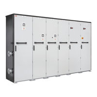
ABB ACS880-607LC Hardware Manual (108 pages)
3-phase dynamic brake units
Brand:
ABB
| Category:
Industrial Equipment
| Size: 6.11 MB
Table of Contents
Table of Contents
5
1 Introduction to the Manual
11
Contents of this Chapter
11
Applicability
11
Safety Instructions
11
Target Audience
11
Categorization by Frame Size and Option Code
12
Use of Component Designations
12
Quick Installation Flowchart
12
Related Documents
13
Terms and Abbreviations
14
2 Operation Principle and Hardware Description
15
Contents of this Chapter
15
Product Overview
15
Operation Principle
15
When Is Resistor Braking Necessary
15
Overview Diagram of the Drive System
16
Overview Drawing of the Drive System
17
Layout Drawings - Brake Module Cubicle
18
Layout Drawing - Brake Module R8I
20
Module Layout
20
Coolant Connectors
21
Connectors X50
21
Fiber Optic Connectors
22
Overview of Power and Control Connections
23
Brake Unit Control Devices
24
Overview of the Control Connections of the BCU Control Unit
24
The Control Panel
25
Control by PC Tools
25
Fieldbus Control
25
DC Switch and Charging Switch
25
Type Designation Labels
26
Type Designation Label of the Brake Unit
26
Type Designation Key
27
Basic Code
27
Option Codes
27
3 Guidelines for Planning the Electrical Installation
31
Contents of this Chapter
31
Limitation of Liability
31
Generic Guidelines
31
Selecting the Brake Resistor
31
Selecting and Routing the Brake Resistor Cables
32
Typical Resistor Cable Sizes
32
Minimizing Electromagnetic Interference
32
Maximum Cable Length
32
Placing the Brake Resistor
32
Selecting the Resistor Thermal Switch Circuit Cable
33
Protecting the System against Thermal Overload
33
Protecting the System against Short-Circuits
33
4 Electrical Installation
35
Contents of this Chapter
35
Electrical Safety Precautions
35
General Notes
37
Printed Circuit Boards
37
Optical Components
37
Measuring the Insulation of the Brake Resistor Circuit
38
Connecting the Brake Resistor Cables and Thermal Switch
38
Connection Diagram
38
Connection Procedure of the Resistor Cables
39
Connection Procedure of the Thermal Switch Cable
40
Connecting the Control Cables
40
Control Cable Connection Procedure
41
Grounding the Outer Shields of the Control Cables at the Cabinet Entry
41
Routing the Control Cables Inside the Cabinet
43
Connecting Control Cabling
43
Connecting a PC
45
5 The Control Unit
47
Contents of this Chapter
47
General
47
BCU-X2 Layout
48
Default I/O Diagram of the Brake Control Unit
50
External Power Supply for the Control Unit (XPOW)
52
The X485 Connector
52
Safe Torque off (XSTO, XSTO OUT)
52
FSO-XX Safety Functions Module Connection (X12)
52
SDHC Memory Card Slot
52
Connector Data
53
BCU-X2 Ground Isolation Diagram
55
6 Installation Checklist
57
Contents of this Chapter
57
Checklist
57
7 Start-Up
59
Contents of this Chapter
59
Start-Up Procedure
59
8 Operating Instructions
61
Contents of this Chapter
61
Disconnecting the Brake Unit from the Drive DC Bus
61
Connecting the Brake Unit to the Drive DC Bus
61
9 Fault Tracing
63
Contents of this Chapter
63
Leds
63
Control Panel and Panel Platform/Holder Leds
63
Control Unit Leds
64
R8I Module Leds
64
7-Segment Display of the Brake Control Unit
64
Warning and Fault Messages
64
10 Maintenance
65
Contents of this Chapter
65
Maintenance Intervals
65
Maintenance Timers and Counters
67
Cabinet
67
Cleaning the Interior of the Cabinet
67
Cleaning the Exterior of the Cabinet
67
Power Connections
68
Retightening the Power Connections
68
Fan Replacement
68
Brake Chopper Module Cubicle
68
Fan in the Output Cubicle, Top Cable Entry (Option +H351)
69
Brake Module
70
Removing the Module
71
Reinstalling the Module
74
Capacitors
74
Reforming the Capacitors
74
Fuses
74
Replacing the Brake Chopper Fuses
74
Replacing the Resistor Fuses
75
Control Panel
77
Cleaning the Control Panel
77
Replacing the Battery
77
Memory Unit
77
Replacing the Memory Unit
77
11 Internal Cooling Circuit
79
Contents of this Chapter
79
Applicability
79
Internal Cooling System
79
Connection to a Cooling Unit
81
Connection to an ACS880-1007LC Cooling Unit
81
Connection to a Custom Cooling Unit
81
General Requirements
81
Coolant Temperature Control
81
Filling up and Bleeding the Internal Cooling Circuit
82
Drive Line-Ups with an ACS880-1007LC Cooling Unit
82
Drive Line-Ups with a Custom Cooling Unit
82
Draining the Internal Cooling Circuit
84
Maintenance Intervals
84
Technical Data
84
Coolant Specification
84
Coolant Type
84
Temperature Limits
84
Pressure Limits
86
Coolant Flow Rate Limits
86
Cooling Circuit Materials
86
12 Technical Data
89
Contents of this Chapter
89
Ratings
89
Definitions
90
Derating
91
Surrounding Air Temperature Derating
91
Coolant Temperature Derating
91
Antifreeze Content Derating
91
Altitude Derating
92
Frame Sizes and Modules Used
92
Fuses
92
DC Fuses (IEC)
92
DC Fuses (UL)
93
Resistor Fuses (IEC and UL)
93
Dimensions, Weights and Free Space Requirements
93
Losses, Cooling Data and Noise
94
Terminal and Cable Entry Data for the Resistor Cables
94
Bottom Entry and Exit of Cables
95
Top Entry and Exit of Cables
97
Tightening Torques
98
Electrical Connections
98
Mechanical Connections
98
Insulation Supports
98
Cable Lugs
98
Typical Resistor Cable Sizes
98
Maximum Cable Length
99
Resistor Connection
99
Control Unit (Board) Connection Data
99
Auxiliary Circuit Current Consumption
99
Efficiency
99
Protection Classes
100
Ambient Conditions
100
Materials
101
Color
101
Package
101
Vertical Package
101
Disposal
102
Applicable Standards
102
Markings
102
Disclaimers
102
Generic Disclaimer
102
Cybersecurity Disclaimer
102
13 Dimension Drawings
103
Contents of this Chapter
103
Brake Unit with Bottom Exit
104
Brake Unit with Top Exit
105
Further Information
107
ABB ACS880-607LC Hardware Manual (74 pages)
1-phase brake units
Brand:
ABB
| Category:
DC Drives
| Size: 3.94 MB
Table of Contents
Table of Contents
5
1 Introduction to the Manual
9
Contents of this Chapter
9
Applicability
9
Safety Instructions
9
Target Audience
9
Related Documents
10
Use of Component Designations
10
Terms and Abbreviations
10
2 Operation Principle and Hardware Description
13
Contents of this Chapter
13
Product Overview
13
Operation Principle
13
Single-Line Diagram of the Drive System
14
Layout
15
Brake Chopper Cubicle
15
Brake Resistor Cabinet
16
Brake Chopper Module
17
Overview of Power and Control Connections
19
Controlling the Brake Chopper from an External Control Location
20
Master-Follower Connection
20
Type Designation Labels
20
Brake Unit Type Designation Label
20
Brake Chopper Module Type Designation Label
21
Brake Unit Type Designation Key
21
Basic Code
21
3 Mechanical Installation
23
Contents of this Chapter
23
Brake Unit
23
Brake Resistor Cabinet
23
User-Defined Brake Resistors
23
4 Planning the Electrical Installation
25
Contents of this Chapter
25
Limitation of Liability
25
Generic Guidelines
25
Selecting the User-Defined Brake Resistors
25
Selecting and Routing the Brake Resistor Cables
26
Typical Resistor Cable Sizes
26
Minimizing Electromagnetic Interference
26
Maximum Cable Length
26
Placing the Brake Resistors
26
Selecting the Resistor Thermal Switch Circuit Cable
27
Protecting the System against Thermal Overload
27
Operation Principle
27
Protecting the System against Short-Circuits
27
5 Electrical Installation
29
Contents of this Chapter
29
Electrical Safety Precautions
29
Checking the Insulation of Brake Resistor and Resistor Cable
31
Connecting the Brake Resistor Cables and Thermal Switch
32
Connection Diagram
32
Connection Procedure
32
6 Installation Checklist of the Drive
35
Contents of this Chapter
35
Checklist
35
7 Start-Up
37
Contents of this Chapter
37
Start-Up Procedure
37
8 Fault Tracing
39
Contents of this Chapter
39
Fault Indications
39
Fan Supervision
40
Selecting the Voltage
40
9 Maintenance
43
Contents of this Chapter
43
Maintenance Intervals
43
Cooling System
44
Retightening the Power Connections
44
Replacing Cooling Fans
45
Brake Chopper Cubicle
45
Brake Resistor Cabinet (Option +D151)
46
10 Internal Cooling Circuit
47
Contents of this Chapter
47
Applicability
47
Internal Cooling System
47
Connection to a Cooling Unit
49
Connection to an ACS880-1007LC Cooling Unit
49
Connection to a Custom Cooling Unit
49
General Requirements
49
Coolant Temperature Control
49
Filling up and Bleeding the Internal Cooling Circuit
50
Drive Line-Ups with an ACS880-1007LC Cooling Unit
50
Drive Line-Ups with a Custom Cooling Unit
50
Draining the Internal Cooling Circuit
52
Maintenance Intervals
52
Technical Data
52
Coolant Specification
52
Coolant Type
52
Temperature Limits
52
Pressure Limits
54
Coolant Flow Rate Limits
54
Cooling Circuit Materials
54
11 Technical Data
57
Contents of this Chapter
57
Ratings
57
Brake Chopper Only
57
Brake Chopper with Factory-Installed Brake Resistors (Option +D151)
58
Definitions
59
DC Fuses
60
Dimensions, Weights and Free Space Requirements
60
Brake Chopper Only
60
Brake Chopper with Factory-Installed Brake Resistors (Option +D151)
60
Losses, Cooling Data and Noise
61
Brake Chopper Only
61
Brake Chopper with Factory-Installed Brake Resistors (Option +D151)
61
Terminal and Lead-Through Data for the Resistor Cable for Brake Units with User-Defined Brake Resistors
62
Resistor Cable Sizes
62
Maximum Cable Length
62
Protection Classes
63
Brake Chopper Cubicle
63
Ambient Conditions
63
Materials
65
Standards and Markings
65
Disclaimers
65
Generic Disclaimer
65
Cybersecurity Disclaimer
66
12 Example Circuit Diagrams
67
Contents of this Chapter
67
Brake Unit with One Brake Chopper Module
68
Brake Chopper Control
69
External Fan Voltage Supply
70
Fan Control for Brake Chopper Cubicle
71
Fan Control for Resistor Cabinet
72
Further Information
73
Advertisement
Advertisement
Related Products
ABB ACS880-07LC
ABB ACS880-M04
ABB ACS880-07-0124A-5
ABB ACS880-07-0260A-5
ABB ACS880+N5350
ABB ACS880-01-07A6-5+N5350
ABB ACS880-07C-0174A-7
ABB ACS880-04F-522A-7
ABB ACS880-01-03A0-5
ABB ACS880-07-0061A-7
ABB Categories
Industrial Equipment
Controller
Measuring Instruments
Battery Charger
DC Drives
More ABB Manuals
Login
Sign In
OR
Sign in with Facebook
Sign in with Google
Upload manual
Upload from disk
Upload from URL