Sign In
Upload
Manuals
Brands
ABB Manuals
Media Converter
ACS880-87LC-4000A/4132A-7
ABB ACS880-87LC-4000A/4132A-7 Manuals
Manuals and User Guides for ABB ACS880-87LC-4000A/4132A-7. We have
1
ABB ACS880-87LC-4000A/4132A-7 manual available for free PDF download: Hardware Manual
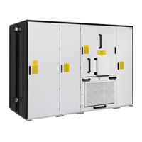
ABB ACS880-87LC-4000A/4132A-7 Hardware Manual (144 pages)
wind turbine converters
Brand:
ABB
| Category:
Media Converter
| Size: 11.53 MB
Table of Contents
Table of Contents
5
1 Safety Instructions
11
Contents of this Chapter
11
Use of Warnings and Notes
11
General Safety in Installation, Start-Up and Maintenance
12
Electrical Safety in Installation, Start-Up and Maintenance
13
Precautions before Electrical Work
13
Additional Instructions and Notes
14
Fiber Optic Cables
15
Opening and Disconnecting the Main Circuit Breaker
16
Disconnecting the Charging Circuit from the Main Circuit
19
Disconnecting the External Auxiliary Power Supply
20
Disconnecting the Internal 230 V and 400 V Auxiliary Power Supply (Terminal X1)
20
Grounding
21
Work on the Liquid Cooling System
22
2 Introduction to the Manual
23
Contents of this Chapter
23
Target Audience
23
Purpose of the Manual
23
Contents of the Manual
24
Related Documents
24
Categorization by Frame Size and Option Code
24
Quick Installation, Commissioning and Operation Flowchart
25
Terms and Abbreviations
26
3 Operation Principle and Hardware Description
29
Contents of this Chapter
29
Operation Principle
29
Generator Control
30
Overview Diagram of the Wind Turbine Converter
31
Layout Drawing
32
Overview of Power and Control Connections
36
Circuit Boards
37
BAMU Board
38
Type Designation Labels
39
Type Designation Key
40
Basic Code
41
Option Codes (Plus Codes)
41
4 Mechanical Installation
43
Contents of this Chapter
43
Safety Instructions
43
Checklist before Mechanical Installation
44
Moving the Converter Package
45
Moving the Converter Package by Fork-Lift
45
Lifting the Converter Package
46
Moving the Converter on Rollers
46
Unpacking
46
Lifting the Converter - ABB Lift Adapter Bars (Customer Variant) Are in Use
47
Lifting the Converter
48
Placing the Converter
49
Fastening the Cabinet to the Floor
50
Internal Cooling Circuit
50
Lifting the Door
51
Miscellaneous
51
Cable Duct in the Floor below the Cabinet
51
Electric Welding
51
5 Planning the Electrical Installation
53
Contents of this Chapter
53
Selecting the Grid Disconnecting Device
53
Checking the Compatibility of the Generator and the Converter
54
Protecting the Generator Insulation and Bearings
54
Selecting the Power Cables
55
General Rules
55
Sufficient Conductivity of the Protective Conductor
55
Typical Power Cable Sizes
57
CE Cables
57
UL Cables
57
Alternative Power Cable Types
57
Power Cable Types for Limited Use
57
Not Allowed Power Cable Types
58
Generator Cable Shield
58
Single Core Vs Multicore Cables in Grid Cabling
59
Additional US and Canada Requirements
59
Conduit
59
Armored Cable / Shielded Power Cable
59
Selecting the DC Resistors
60
Selecting the Control Cables
60
General Rules
60
Relay Cable
60
Routing the Cables
61
Control Cable Ducts
61
Protecting the Converter Installation
62
Protecting the Grid Cable in Short-Circuit Situations
62
Protecting the Generator and Generator Cable in Short-Circuit Situations
62
Protecting the Converter, Generator Cable and Grid Cable against Thermal Overload
62
Protecting the Converter against Ground Faults in the Generator or Generator Cable
62
Protecting the Converter against Ground Faults in the Converter or Grid Cable
62
Implementing the Emergency Stop Function
63
Implementing the Grid Fault Ride-Through Function
63
Supplying Power for the Auxiliary Circuits
63
Using a Safety Switch between the Converter and Generator
64
Using a Contactor between the Converter and Generator (Option +F269)
64
Protecting the Contacts of Relay Outputs
64
6 Electrical Installation
67
Contents of this Chapter
67
Checking the Insulation of the Assembly
67
Converter
67
Grid Cable
68
Generator Stator and Generator Cable
68
Integrated DC Chopper and DC Resistor (Option +D150+D151)
68
Connecting the Grid Cables/Busbars
68
Connection Diagram
68
Connection Procedure
69
Connecting the Generator Cables
70
Connection Diagram
70
Connection Procedure
70
Connecting the External Power Supply Cable for the Auxiliary Circuit
72
Connecting the Control Cables
73
Default I/O Connection Diagrams
76
Connecting a PC
76
7 Installation Checklist
77
Contents of this Chapter
77
Before You Start
77
Checklist
78
8 Maintenance
79
Contents of this Chapter
79
Maintenance Intervals
80
Maintenance Timers and Counters
81
Cabinet
82
Replacing Inlet (Door) Filter (IP54, Customer Variant)
82
Power Connections
83
Tightening
83
Fans
83
Replacing the Cooling Fan of the Converter Module
84
Replacing the Fan of the Main Breaker Cubicle
86
Replacing the Cooling Fan of the Auxiliary Control Cubicle
89
Replacing the Upper Cooling Fan of the LCL Filter Cubicle
91
Replacing the Lower Cooling Fan of the LCL Filter Cubicle
93
Fuses
95
Replacing the DC Fuses
95
Replacing the AC Fuses
96
Converter Module
97
Replacing the Converter Module
97
Capacitors
103
BCU Control Unit
104
Replacing the Memory Unit
104
Replacing the Real-Time Clock Battery
104
Replacing the SD/SDHC Memory Card
104
Replacement Illustration
105
Main Circuit Breaker
105
9 Technical Data
107
Contents of this Chapter
107
Ratings
107
Definitions
108
Derating
108
Temperature Derating
108
Altitude Derating
108
Type Equivalence Table
108
Fuses
109
Main Circuit AC Fuses
109
Main Circuit DC Fuses
109
Fuses for the Voltage Measurement Board BAMU
109
Dimensions, Weights and Free Space Requirements
109
Losses, Cooling Data and Noise
110
Internal Cooling Circuit Data
110
Terminal and Lead-Through Data for the Grid Connection
110
Tightening Torques
110
Terminal and Lead-Through Data for the Generator Cable
111
Grid Specification
111
Requirements for the Grid Connection
111
Generator Connection Data
112
BCU Control Unit
112
Efficiency
112
Degree of Protection
112
Environmental and Corrosion Classification
112
Ambient Conditions
113
Materials
114
Auxiliary Circuit Current Consumption
114
ACS880-87LC-4000A/4021A-7 and ACS880-87LC-4000A/4132A-7
114
UPS Supply
114
Non-UPS Supply
114
Applicable Standards
115
CE Marking
115
Compliance with the European Low Voltage Directive
115
Compliance with the European EMC Directive
115
Compliance with the European Machinery Directive
115
Regulatory Compliance Mark (RCM)
116
EAC Marking
116
Compliance with en 61800-3:2004/A1:2012
116
Definitions
116
Category C4
117
ETL Marking
117
DNV-GL Renewable Certification Marking
117
WEEE Marking
118
Disclaimers
118
Generic Disclaimer
118
Cybersecurity Disclaimer
118
10 Control Units of the Converter
119
Contents of this Chapter
119
General
119
BCU Control Unit
119
Layout and Connections
120
BCU Layout and Connections
120
Control Unit Connector Data
122
11 Dimension Drawings
125
Contents of this Chapter
125
12 Cooling and Heating
129
Contents of this Chapter
129
Hardware Description
129
General
129
Diagram of the Internal Cooling and Heating Circuit
129
Planning the Cooling System
131
Connection to a Customer Cooling Unit
131
General Requirements
131
Coolant Temperature Control
131
Mechanical Installation
132
Connecting the Internal Cooling Circuit to a Customer Cooling Unit
132
Connecting the Liquid Pipes
132
Filling up and Bleeding the Internal Cooling Circuit
133
Converters with a Customer Cooling Unit
133
Draining the Internal Cooling Circuit
134
Cooling Station Control
134
Specifications
136
Temperature Limits
136
Pressure Limits
136
Water Quality
137
Freeze Protection and Corrosion Inhibition
137
Coolant Concentration
137
Liquid Mixture Quality
137
Approved Coolants
138
Materials
138
Heating
139
Cold Start (-30 °C
139
Normal Start (-30 °C
139
Circuit Diagram
141
Further Information
143
Product and Service Inquiries
143
Product Training
143
Providing Feedback on ABB Drives Manuals
143
Advertisement
Advertisement
Related Products
ABB ACS880-87LC-4000A/4021A-7
ABB ACS880-87LC-3200A
ABB ACS880-87LC-3200A-7
ABB ACS880-1604
ABB ACS880-1607
ABB ACS880-1604LC
ABB ACS880-1607LC
ABB ACS880-87CC
ABB ACS880-77CC
ABB ACS800-67LC
ABB Categories
Industrial Equipment
Controller
Measuring Instruments
Battery Charger
DC Drives
More ABB Manuals
Login
Sign In
OR
Sign in with Facebook
Sign in with Google
Upload manual
Upload from disk
Upload from URL