Sign In
Upload
Manuals
Brands
ABB Manuals
Industrial Equipment
LVS Digital
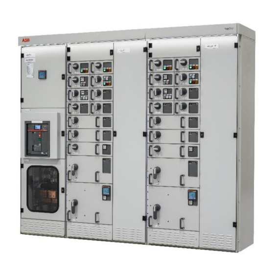
ABB LVS Digital Manuals
Manuals and User Guides for ABB LVS Digital. We have
2
ABB LVS Digital manuals available for free PDF download: Manual
ABB LVS Digital Manual (80 pages)
with M10x Motor Controller
Brand:
ABB
| Category:
Industrial Equipment
| Size: 2.11 MB
Table of Contents
Table of Contents
3
1 General
9
Target Group
9
Use of Warning, Caution, Information and Tip Icon
9
Terminology
10
Related Documentation
13
2 Introduction
14
Figure 2: General LVS Digital System Configuration with M10X-M
14
Figure 3: General LVS Digital System Configuration with M10X-TCP
15
Hardware Types and Technical Data
16
Table 1 Digital Gateway Modbus Hardware
16
Table 2 M10X Motor Controller Variants
16
Table 3 Digital Gateway Technical Data
17
Modbus Standard
18
Basics
18
Figure 4 Master Slave Query Response Cycle
18
Table 4 Modbus RTU Mode of Transmission
20
3 Interfaces
21
Front View
21
Figure 5 Digital Gateway Front View
21
Table 5 Front View Connectors, LED and Push Buttons
22
Power Supply
23
Figure 6 Power Supply Connector
23
4 Digital Gateway Installation
24
Digital Gateway Mounting
24
Figure 7 Digital Gateway Mounting Kit for MNS
24
CF Card Installation
25
Figure 8 CF Card Insertion
25
Figure 9 CF Card Insertion Detail
25
5 Communication Interface Connection
26
Switchgear Bus Network
26
M10X-M Motor Controller
26
Figure 10 Hardware Connection between Digital Gateway and M10X-M
26
Table 6 M10X Communication Setting
26
M10X-TCP Motor Controller
27
Figure 11 Shielding Clamp for RS485
27
Figure 12 Hardware Connection between Digital Gateway and M10X-TCP
27
Switchgear Control Network
28
Connection Examples of Switchgear Control Network
28
Figure 13 Digital Gateway Directly Connected to CMES Edge
28
Figure 14 Network Connection of Digital Gateway and CMES Edge
29
Time Synchronization
30
Option 1
30
Figure 15 Example, Showing 3Rd Party Network Switch and 3Rd Party NTP Server in a Switchgear Control Network
30
Option 2
31
Figure 16 Example, Using Digital Gateway as NTP Server
31
DCS Fieldbus
32
Modbus RTU Topology
32
Figure 17 Digital Gateway RS232 Connection Via Serial 2 to DCS
32
Figure 18 Digital Gateway RS422 Connection Via Serial 2 to DCS
33
Figure 19 Digital Gateway RS485 Connection Via Serial 2 to DCS
34
Figure 20 Example for RS485 Bus Termination and Biasing
34
Modbus TCP Topology
35
Figure 21 Digital Gateway Modbus TCP Connection with Crossover Cable
35
Figure 22 Digital Gateway Modbus TCP Connection with Standard CAT5 Cable
35
6 Redundancy
36
Redundant Architecture
36
Figure 23 Redundant Configuration and Possible Failure Scenario - M10X-M
36
Figure 24 Redundant Configuration and Possible Failure Scenario - M10X-TCP
37
Redundancy Configuration
38
Redundant Digital Gateway Connection
38
Figure 25 Serial 1 to Serial 1 Redundant Link Connections with Ferrite Core
38
Table 7 Serial Redundant Link Cable Ordering Code
38
M10X Redundant Configuration
39
Digital Gateway Redundant Configuration
39
Figure 26 Mnavigate IP Address Parameterization for Primary and Backup Digital Gateway
39
Table 8 M10X-M Redundant Communication Setting
39
Figure 27 Mnavigate Fieldbus Slave Address Parameterization for Primary and Backup Digital Gateway
40
Table 9 Primary and Backup IP Address Setting
40
Handling of Redundancy Faults
41
Table 10 Primary and Backup IP Address Setting
41
Mview / Web Interface
42
Figure 28 Mview Redirecting to Redundant Digital Gateway
42
Figure 29 Redundancy Error Shown in Mview by a Red Square
42
7 Configurations
43
Initial Values - IP Configuration
43
Settings - IP Configuration
44
Figure 30 IP Address Settings
44
Figure 31 Time Sync Settings
44
Table 11 Digital Gateway Default Parameters - IP Configuration
44
Definition of IP Addresses
45
Settings - Serial Switchgear Bus
46
Table 12 Digital Gateway Serial Switchgear Bus
46
Settings - DCS Modbus RTU Communication
47
Figure 32 Parameter Window for Serial Switchgear Bus in Mnavigate
47
Figure 33 Parameter Window for MODBUS RTU Parameters in Mnavigate
48
Table 13 Digital Gateway Default Parameters - Modbus RTU Configuration
48
Settings - DCS Modbus TCP Communication
49
Table 14 Digital Gateway Default Parameters - Modbus RTU Configuration
49
Multiple Master in Modbus TCP Applications
50
Failsafe
50
Figure 34 Parameter Window for MODBUS TCP Parameters in Mnavigate
50
Start-Up of Digital Gateway and Application Download
51
Power-On Procedure
51
Power on the Control Voltage Supply
51
Confirm Operation
51
8 Function Codes
52
Message Format
52
Query Messages
52
Response Messages
52
Table 15 Function Codes
52
Function Code 02 - Read Input Status
53
Function Code 03 - Read Holding Registers
53
Function Code 04 - Read Input Registers
53
Table 16 Address Ranges of Function Codes
53
Data Presentation for Function Code 03 and 04
54
Function Code 06 - Preset Single Register
54
Function Code 08 - Preset Single Register
54
Table 17 Byte Representation for Function Code 03 and 04
54
Table 18 Byte Representation for Float
54
Table 19 Byte Representation for Float Big Endian
54
Function Code 16 - Preset Multiple Register
55
Restrictions
55
General
55
Exception Code Handling
56
9 Data Mapping
57
User Data Map
57
Default Data Map
57
Monitoring (Inputs from M10X)
57
Monitoring with Function Code 02
58
Table 20 Default Modbus Map Life Bit of M10X
58
Table 21 Default Modbus Map Bit Status of M10X
62
Monitoring with Function Code 03 and 04
63
Table 22 Default Modbus Map Measured Values of M10X
63
Extended Status Description
64
Table 23 Default Modbus Map Extended Status for M10X
64
Table 24 Extended Status Byte 1
64
Table 25 Extended Status Byte 2
65
Table 26 Extended Status Byte 3
65
Table 27 Extended Status Byte 4
66
Control Commands
67
Table 28 Default Modbus Command Registers
67
Switching Commands
68
Table 29 Switching Commands Sent from DCS to Digital Gateway
68
Switching Commands - Bit Control
69
Table 30 Default Modbus Bit Command Registers
69
Table 31 Default Bit Map Control Commands Low Byte
69
Redundant Digital Gateway Modbus Data
70
Figure 1: Digital Gateway
70
Table 32 Default Bit Map Control Commands High Byte
70
Table 33 Redundant Data for Monitoring by the Modbus Master
70
Table 34 Redundant Command Possible from the Modbus Master
70
Control Access
71
Table 35 Command and Status for Control Access
71
10 Troubleshooting and Maintenance
73
Digital Gateway LED Indication
73
Table 36 Digital Gateway LED Indication
75
Troubleshooting
76
Table 37 Digital Gateway Troubleshooting
77
Advertisement
ABB LVS Digital Manual (64 pages)
With UMC Motor Controller, Interface Manual Profibus
Brand:
ABB
| Category:
Gateway
| Size: 1.72 MB
Table of Contents
Table of Contents
3
General
9
Target Group
9
Use of Warning, Caution, Information and Tip Icon
9
Terminology
10
Related Documentation
13
PROFIBUS Additional Guidelines
13
Introduction
14
Figure 1: Digital Gateway
14
Figure 2: LVS Digital System Configuration with UMC
14
Hardware Types and Technical Data
15
Table 1 Digital Gateway Profibus Hardware
15
Table 2 Digital Gateway Technical Data
15
PROFIBUS Standard
16
Profibus Dp-V0
16
Cyclic Data Communication
16
Figure 3 Cyclic User Data Transmission in DP
16
Diagnostic
17
Sync and Freeze Mode
17
DP Master Class 1 (DPM1) and Class 2 (DPM2)
17
Monitoring the DP-V0 Communication
17
Profibus Dp-V1
18
Acyclic Data Communication
18
Figure 4 Acyclic Communication in DP-V1: Read Service
18
Interfaces
19
Front View
19
Figure 5 Digital Gateway Front View
19
Table 3 Front View Connectors, LED and Push Buttons
20
Power Supply
21
Figure 6 Power Supply Connector
21
Digital Gateway Installation
22
Digital Gateway Mounting
22
Figure 7 Digital Gateway Mounting Kit
22
CF Card Installation
23
Figure 8 CF Card Insertion
23
Figure 9 CF Card Insertion Detail
23
Communication Interface Connection
24
Switchgear Bus Network
24
Figure 10 Different Hardware Connections Possible between Digital Gateway and MTQ22
24
Switchgear Control Network
25
Connection Examples of Switchgear Control Network
26
Figure 11 Digital Gateway Directly Connected to LVS Digital Edge Gateway
26
Figure 12 Network Connection of Digital Gateway and LVS Digital Edge Gateway
27
Time Synchronization
28
Option 1
28
Figure 13 Example, Showing 3Rd Party Network Switch and 3Rd Party NTP Server in a Switchgear Control Network
28
Option 2
29
Figure 14 Example, Using Digital Gateway as NTP Server
29
Fieldbus
30
Profibus
30
Figure 15 Digital Gateway PROFIBUS Connection and Termination Examples
30
Table 4 Maximum Segment Cable Length for RS485
31
Table 5 Maximum Stub Length for RS485
31
Redundancy
32
Redundant Architecture
32
Figure 16 Redundancy Configuration and Possible Failure Scenario
32
Redundancy Configuration
33
Redundant Digital Gateway Connection
33
Figure 17 Serial 1 to Serial 1 Redundant Link Connections with Ferrite Core
33
Table 6 Serial Redundant Link Cable Ordering Code
33
Digital Gateway Redundant Configuration
34
Figure 18 Mnavigate IP Address Parameterization for Primary and Backup Digital Gateway
34
Table 7 Primary and Backup IP Address Setting
34
Figure 19 Mnavigate Fieldbus Slave Address Parameterization for Primary and Backup Digital Gateway
35
Handling of Redundancy Faults
36
Table 8 Primary and Backup IP Address Setting
36
Mview / Web Interface
37
Figure 20 Mview Redirecting to Redundant Digital Gateway
37
Figure 21 Redundancy Error Shown in Mview by a Red Square
37
Configurations
38
Initial Values - IP Configuration
38
Settings - IP Configuration
39
Figure 22 IP Address Settings
39
Figure 23 Time Sync Settings
39
Table 9 Digital Gateway Default Parameters - IP Configuration
39
Definition of IP Addresses
40
Settings - PROFIBUS Communication
41
Figure 24 Parameter Window for PROFIBUSDP Parameters in Mnavigate
41
Table 10 Digital Gateway Default Parameters - PROFIBUS Configuration
41
Addressing
42
Figure 25 Example of Max Address Range and Slave Numbers on One PROFIBUS Master
42
Failsafe
43
Start-Up of Digital Gateway and Application Download
43
Power-On Procedure
43
Power on the Control Voltage Supply
43
Confirm Operation
43
Data Mapping
44
User Data Map
44
Default Data Map
44
Cyclic Data Communication (DP-V0)
45
Figure 26 Mapping Selection from Mnavigate
45
Table 11 244 Byte Cyclic Data Structure
45
Table 12 Monitoring Data Structure of a Single UMC
45
Status Bit Explanation
46
Commands (Output to Field Device from Master)
47
Table 13 Explanation of Status Bit
47
Table 14 122 Byte Cyclic Data Structure
47
Table 15 Command Data Structure of UMC
47
Command Bits Explanation
48
Table 16 Command Data Bits Explanation
48
Handling of Commands and Priority
49
Redundant Digital Gateway Profibus Data
50
Table 17 Redundant Data for Monitoring by the Profibus Master
50
Table 18 Redundant Command Possible from the Profibus Master
50
Control Access
51
Table 19 Command and Status for Control Access
51
Acyclic Data Communication (DP-V1 -Master Class 1)
53
Table 20 Default DP-V1 Data
54
Table 21 Extended Status Byte 58
54
Table 22 Extended Status Byte 59
55
Table 23 Extended Status Byte 60
55
Table 24 Extended Status Byte 61
56
Troubleshooting and Maintenance
57
Digital Gateway LED Indication
57
Table 25 Digital Gateway LED Indication
59
Troubleshooting
60
Table 26 Digital Gateway Troubleshooting
61
Advertisement
Related Products
ABB LF121085-D
ABB L-VD4
ABB L-SEC
ABB Advance Optima limas11
ABB LMT Series
ABB LST300 Series
ABB LON 670 Series
ABB LP
ABB L5712
ABB Switchsync L183
ABB Categories
Industrial Equipment
Controller
Measuring Instruments
Battery Charger
DC Drives
More ABB Manuals
Login
Sign In
OR
Sign in with Facebook
Sign in with Google
Upload manual
Upload from disk
Upload from URL