Sign In
Upload
Manuals
Brands
ABB Manuals
Industrial Equipment
R-MAG 38kV 1250/2000A
ABB R-MAG 38kV 1250/2000A Manuals
Manuals and User Guides for ABB R-MAG 38kV 1250/2000A. We have
1
ABB R-MAG 38kV 1250/2000A manual available for free PDF download: Instruction Manual
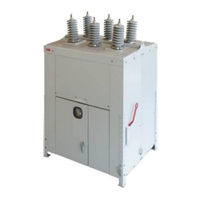
ABB R-MAG 38kV 1250/2000A Instruction Manual (56 pages)
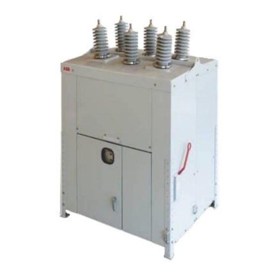
Medium Voltage Outdoor Dead Tank Vacuum Magnetic Circuit Breaker
Brand:
ABB
| Category:
Industrial Equipment
| Size: 2.07 MB
Table of Contents
Table of Contents
2
Safety Notices
4
Figure 1 Hazardous Voltage Nameplate
4
Introduction
5
Receiving, Handling and Storage
5
Receiving Inspection
5
Handling
5
Storage
6
General Description
6
High-Voltage Assembly
6
Figure 2 Lifting Detail
6
Standard Production Tests
7
Magnetic Actuator
7
Actuator Controller
7
Housing
7
Operation
8
Closing
8
Opening
8
Manual Trip Handle Operation
8
Figure 3 Trip Handle Position Sticker
8
Operational Check Prior to Installation (Electrical Close/Open)
9
Installation
9
Mounting
9
Grounding
9
Final Inspection
10
Control Power
10
Arrester Protection
10
Inspection, Maintenance and Adjustment
11
Maintenance Steps
11
High-Pot Test
12
Measuring Contact Travel
12
Figure 4 Interrupter Assembly 38 Kv, 1250 a
15
Figure 5 Interrupter Assembly 38 Kv, 2000 a
16
Figure 6 Trip Handle
17
Figure 7 ABB R-MAG - Vacuum Interrupter Electrical Switching Life Curves (31.5 Ka)
18
Figure 8 ABB R-MAG - Vacuum Interrupter Electrical Switching Life Curves (40 Ka)
19
Figure 9 High Voltage Cabinet Layout
20
Figure 10 Typical Schematic Diagram
21
Figure 11 Typical Outline, 1250 a
22
Figure 12 Typical Outline, 2000 a
23
Kv R-MAG ELECTRICAL SPECIFICATIONS
24
Table 1 R-MAG 38 Kv, 31.5 Ka Ratings
24
Table 2 R-MAG 38 Kv, 40 Ka Ratings
25
Typical Current Transformer Connections
26
Table 3 Typical Current Transformer Connections
26
Auxiliary Switch Current Specifications
27
Control Board Voltage Requirements
27
Table 4 Auxiliary Switch Current Specifications
27
Table 5 Control Board Voltage Requirements
27
Breaker Nameplate
28
Renewal Parts
28
Product Recycling
28
Figure 13 Breaker Nameplate
28
Appendix A
30
Apx Figure 1 Electrical System Block Diagram
32
Overview
32
Auxiliary Open / Safe Open (KM1005, CH 3, Pins 5 and 6)
33
Binary Inputs
33
Control Boards Available/Magnetic Actuator Coil Energizing Capacitor
33
Remote Close (KM1005, CH 1, Pins 1 and 2)
33
Remote Open (KM1005, CH 2, Pins 3 and 4)
33
Apx Table 1 DIP Switch Thresholds
34
Circuit Breaker Close Blocking (KM1005, CH 6, Pins 11 and 12)
34
Protection Trip / Second Trip (KM1005, CH 4, Pins 7 and 8)
34
Under Voltage Trip (KM1005, CH 7, Pins 13 and 14)
34
Binary Outputs
35
Circuit Breaker Auxiliary Closed (KM1004 Pins 7 and 8)
35
Circuit Breaker Auxiliary Open (KM1004 Pins 5 and 6)
35
Circuit Breaker Closed (KM1004 Pins 3 and 4)
35
Circuit Breaker Opened (KM1004 Pins 1 and 2)
35
Circuit Breaker Remote Open (KM1004 Pins 13 and 14)
35
Unit Not Ready (KM1004 Pins 11 and 12)
35
Unit Ready (KM1004 Pins 9 and 10)
35
Apx Table 2 Output Contact Specifications
36
Actuator Close and Trip Coil Continuity Monitor
37
Apx Figure 2 Electrical Load Curves
37
Energy Failure Auto Trip
37
Features
37
Temperature Protection
37
Wrong Position Auto Trip
37
Apx Table 3 CB Operation Vs. Available Capacitor Charge
38
Power Considerations
38
Reduced Power Consumption
38
RS-232 Port / JTAG Communication Port
38
Capacitor Life
39
Discharging Storage Unit Capacitors
39
Apx Table 4 Circuit Breaker Condition Vs. Position
40
Breaker Ready / Not Ready Binary Output Contacts and Ready Light Status
40
Apx Figure 3 Standard Actuator Circuit Board and Connection Diagram
41
Standard Actuator Circuit Board and Connection Diagram
41
Apx Table 5 KM1001 - Breaker Position (CB Position)
42
Apx Table 6 KM1002 - Power Output and Capacitor Link
42
Control Board Connectors
42
Apx Figure 4 Standard Actuator Circuit Board and DIP Switch Settings
43
Default Jumper and Dip Switch Settings
43
Apx Figure 5 Ready LED Continually Flashing
44
Troubleshooting Flowcharts
44
Apx Figure 6 Ready LED off
45
Apx Figure 7 Conditions for CB Not Opening/Closing
46
Apx Figure 8 Standard Actuator Control Board and Pin Assignments
47
Instructions for Troubleshooting a Control Board
47
Ready Light Is off
48
Specific Line Item Check Is Shown below
49
Apx Table 7 Breaker Troubleshooting Guide
52
Instructions for Changing out a Control Board
52
Apx Figure 10 Control Board, Simplified
54
Apx Figure 9 Control Board with Terminal Numbering
54
Apx Figure 11 ED2.0 Control Board Parts and Mounting
55
Advertisement
Advertisement
Related Products
ABB 364DS
ABB 364PS
ABB 340/2.8
ABB 325/3.1
ABB GridShield 3P
ABB GridShield 3SP
ABB OVRHSP 3803D Series
ABB 3AXD50000035158
ABB R-MAG
ABB R-MAG Series
ABB Categories
Industrial Equipment
Controller
Measuring Instruments
Battery Charger
DC Drives
More ABB Manuals
Login
Sign In
OR
Sign in with Facebook
Sign in with Google
Upload manual
Upload from disk
Upload from URL