Sign In
Upload
Manuals
Brands
Brother Manuals
Sewing Machine
PR-600
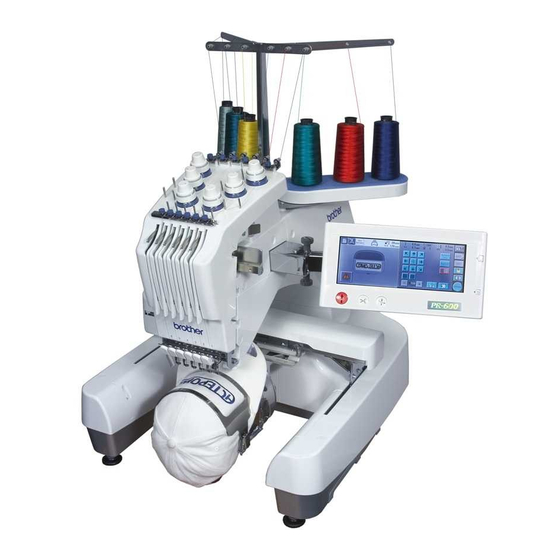
Brother PR-600 Manuals
Manuals and User Guides for Brother PR-600. We have
6
Brother PR-600 manuals available for free PDF download: Service Manual, Manual, Quick Reference Manual, Parts Reference List, User Manual, Supplementary Manual
Brother PR-600 Service Manual (272 pages)
Professional embroidery machine
Brand:
Brother
| Category:
Sewing Machine
| Size: 21.61 MB
Table of Contents
Table of Contents
3
1 Outline of Mechanism
11
Main Mechanisms
12
Driveline
13
Positions of Electronic Components
15
Control System Block Diagram
17
Operation of Other Electronic Components
18
Using the Thread
19
2 Disassembly
21
Main Parts
22
Motor Cover and Carriage Cover Removal
23
Bed Cover Removal
24
Arm Cover R Removal
25
Arm Cover L Removal
26
Base Cover R Removal
27
Base Cover L Removal
28
Oil Box Holder Removal
28
Main PCB Assembly Removal
29
Spool Stand Frame Final Assembly Removal
29
Operation Panel Assembly Removal
29
Thread Take-Up Cover Removal
30
Tension Base Removal
30
Needle Plate Removal
31
Needle Plate Base Assembly Removal
31
Needle Plate Base Disassembly
31
Picker Bracket Removal
32
Picker Bracket Disassembly
32
Rotary Hook Removal
32
Cutter Unit Final Assembly and Picker Final Assembly Removal
33
Feed Unit
34
T-Belt (Y-Guide) Removal
35
Feed Final Assembly Removal
36
Y-Motor Final Assembly Removal
37
Y-Motor Disassembly
37
Y-Driving Shaft Assembly Removal
38
Cord Grip Removal
38
FFC and X-Area Sensor Assembly Removal
39
Y-Frame Spacer and X-Belt Presser Removal
39
X-Feed Frame B Removal
39
X-Carriage a Assembly and X-Carriage B Assembly Removal
40
X-Sensor Dog Removal
40
Hoop Sensor Removal
41
X-Guide Shaft Removal
41
T-Belt (Y-Drive) Removal
42
Feed Frame Disassembly
42
Y-Carriage L Disassembly
43
Y-Carriage R Disassembly
44
Connect PCB Disassembly
44
Needle Thread Unit
45
Needle Thread Assembly Removal
46
Hook Holder Assembly Removal
46
Rack and Hook Holder Link Removal
47
Thread Motor Assembly Removal
48
Needle Bar Change Unit
49
Change Box Removal
50
Change Box Disassembly (Step 1)
50
Change Box Disassembly (Step 2)
51
Thread Wiper Unit
52
Thread Presser Base Removal
53
Thread Presser Base Disassembly
53
Wiper Set Assembly Removal
53
Wiper Guide and Wiper Sensor Removal
54
Wiper Set Disassembly
55
Needle Bar Unit
56
Needle Bar Case Final Assembly Removal
57
Change Roller Base Assembly Removal
57
Case Guide D Removal
57
Thread Take-Up Lever Assembly Removal
58
Thread Take-Up Lever Disassembly
58
Needle Bar Removal
59
Needle Bar Case Disassembly
59
Case Positioning Plate Assembly Removal
59
Case Positioning Plate Disassembly
60
Case Bracket Assembly Removal
60
Case Bracket Disassembly
61
Case Guide UL Disassembly
61
Upper Shaft Unit
62
Main Motor Final Assembly Removal
63
Main Motor Disassembly
63
Driving Jump Assembly Removal
64
Driving Jump Disassembly
65
Base Needle Bar Removal
66
J-Clamp Disassembly
66
Presser Foot Vertical Base Disassembly
67
Thread Take-Up Driving Lever Final Assembly Removal
67
Thread Take-Up Driving Lever Disassembly
68
Main Shaft Sensor Final Assembly Removal
69
Crank Rod Removal
69
Pressure Foot Driving Shaft Assembly Removal
70
Presser Foot Driving Shaft Disassembly
70
Upper Shaft Assembly Removal
71
Lower Shaft Unit
72
Arm Bed and Base Frame Disconnection
73
Idle Pulley Assembly Removal
73
Idle Pulley Disassembly
73
Lower Shaft Removal
74
Power Unit
75
Power Switch Assembly and Inlet Removal
76
USB PCB Assembly and Y-Area Sensor Assembly Removal
77
Power PCB Assembly Removal
78
Power PCB Disassembly
78
Adjust-Bolt Removal
79
Thread Cut Unit
80
Picker Disassembly
81
Cutter Unit Disassembly (Step 1)
82
Cutter Unit Disassembly (Step 2)
83
Thread Tension Unit
84
Loosen the Tension Nut Removal
85
Tension Base Bracket Removal
85
Inner Thread Eyelet Base Removal
86
Thread Sensor PCB Assembly and Head PCB Assembly Removal
86
Upper Thread Eyelet Base Removal
87
Antenna Disassembly
88
Spool Stand Frame Disassembly (Step 1)
89
Spool Stand Frame Disassembly (Step 2)
89
Thread Take-Up Lever Cover Disassembly (Step 1)
90
Thread Take-Up Lever Cover Disassembly (Step 2)
91
Thread Take-Up Bracket Disassembly
92
Operation Panel
93
FD Assembly Removal
94
FD Disassembly (Step 1)
94
FD Disassembly (Step 2)
95
Operation Panel Lever Assembly Removal
95
Operation Panel Lever Disassembly (Step 1)
96
Operation Panel B Removal
97
Panel PCB Assembly Removal
98
LCD Removal
99
Touch Panel Removal
99
Button Removal
100
3 Assembly
101
Operation Panel
102
Button Attachment
103
Touch Panel Attachment
103
LCD Attachment
104
Panel PCB Assembly Attachment
105
Operation Panel B Attachment
106
Operation Panel Lever Assembly (Step 1)
107
Operation Panel Lever Assembly (Step 2)
107
Operation Panel Lever Assembly Attachment
108
FD Assembly (Step 1)
109
FD Assembly (Step 2)
110
FD Assembly Attachment
111
Thread Tension Unit
112
Thread Take-Up Bracket Assembly
113
Thread Take-Up Lever Cover Assembly (Step 1)
114
Thread Take-Up Lever Cover Assembly (Step 2)
115
Spool Stand Frame Assembly (Step 1)
116
Spool Stand Frame Assembly (Step 2)
116
Antenna Assembly (Step 1)
117
Antenna Assembly (Step 2)
117
Antenna Assembly Attachment
118
Upper Thread Eyelet Base Attachment
118
Thread Sensor PCB Assembly and Head PCB Assembly Attachment
119
Inner Thread Eyelet Base Attachment
120
Tension Base Bracket Attachment
120
Tension Base Lead Wire Assembly Attachment
121
Tension Nut Attachment
121
Thread Cut Unit
122
Cutter Unit Assembly (Step 1)
123
Cutter Unit Assembly (Step 2)
124
Picker Assembly
125
Power Unit
126
Adjust Bolt Attachment
127
Power PCB Assembly
128
Power PCB Assembly Attachment
129
USB PCB Assembly and Y-Area Sensor Assembly Attachment
130
Power Switch Assembly and Inlet Attachment
131
Lower Shaft Unit
132
Lower Shaft Attachment
133
Idle Pulley Assembly
134
Idle Pulley Assembly Attachment
134
Connection of Arm Bed and Base Frame
135
Upper Shaft Unit
136
Upper Shaft Assembly Attachment
137
Presser Foot Driving Shaft Assembly
138
Presser Foot Driving Shaft Assembly Attachment
139
Crank Rod Assembly Attachment
140
Main Shaft Sensor Final Assembly Attachment
141
Thread Take-Up Driving Lever Final Assembly
142
Thread Take-Up Driving Lever Final Assembly Attachment
143
Presser Foot Vertical Base Final Assembly
144
Vertical Set Assembly
145
Base Needle Bar Attachment
146
Driving Jump Assembly (1)
147
Driving Jump Assembly (2)
149
Driving Jump Assembly Attachment
149
Tension Pulley Assembly Attachment
149
Main Motor Final Assembly
150
Main Motor Final Assembly Attachment
150
Needle Bar Unit
151
Case Guide UL Assembly
152
Case Bracket Assembly
153
Case Bracket Assembly Attachment
154
Case Positioning Plate Assembly
155
Case Positioning Plate Assembly Attachment
155
Needle Bar Case Final Assembly
155
Needle Bar Attachment
156
Thread Take-Up Lever Assembly
157
Thread Take-Up Lever Assembly Attachment
158
Case Guide D Attachment
159
Change Roller Base Assembly Attachment
159
Needle Bar Case Final Assembly Attachment
160
Thread Wiper Unit
161
Wiper Set Assembly
162
Wiper Guide and Wiper Sensor Attachment
163
Wiper Set Assembly Attachment
164
Thread Presser Base Assembly
165
Thread Presser Base Attachment
165
Needle Bar Change Unit
166
Change Box Assembly (Step 1)
167
Change Box Assembly (Step 2)
168
Change Box Assembly (Step 3)
169
Change Box Assembly Attachment
169
Needle Thread Unit
170
Thread Motor Assembly Attachment
171
Rack Assembly and Hook Holder Link Attachment
172
Hook Assembly
172
Needle Thread Assembly Attachment
173
Feed Unit
174
Connect PCB Final Assembly
175
Y-Carriage R Assembly
176
Y-Carriage L Assembly
177
Feed Frame Assembly Attachment
178
T-Belt (X-Drive) Attachment
179
X-Guide Shaft Attachment
180
Hoop Sensor Attachment
181
X-Sensor Dog Attachment
182
X-Carriage a Assembly and X-Carriage B Assembly Attachment
183
X-Feed Frame B Attachment
184
Y-Frame Spacer and X-Belt Presser Attachment
185
FFC and X-Area Sensor Assembly Attachment
186
Cord Grip Attachment
187
Y Driving Shaft Assembly Attachment
188
Y-Motor Final Assembly
189
Y Motor Final Assembly Attachment
190
Feed Final Assembly Attachment
191
T-Belt (Y-Guide) Attachment
192
Main Unit
192
Cutter Unit Final Assembly and Picker Final Assembly Attachment
194
Rotary Hook Attachment
195
Picker Bracket Final Assembly
195
Picker Bracket Final Assembly Attachment
195
Needle Plate Base Assembly
196
Needle Plate Base Assembly Attachment
197
Needle Plate Attachment
197
Tension Base Attachment
198
Thread Take-Up Lever Cover Attachment
199
Operation Panel Assembly Attachment
199
Spool Stand Frame Final Assembly Attachment
200
Main PCB Assembly Attachment
201
Oil Box Holder Attachment
202
Base Cover L Attachment
202
Base Cover R Attachment
203
Arm Cover L Attachment
204
Arm Cover R Attachment
205
Bed Cover Attachment
206
Motor Cover / Carriage Cover Attachment
207
4 Adjustment
209
Adjustment Flow
210
Bent Needle
211
Blunt Needle
212
Starting Test Mode / Selecting Adjustment Test Mode
213
Main Board Test Mode
214
Test Mode
214
Panel Board Test Mode
220
Starting Test Mode / Selecting Adjustment Test Mode
220
How to Read Needle Bar Numbers on Bar Code
223
Main Board Test Mode
223
Motor Belt Tension Adjustment
224
Timing Belt Tension Adjustment
225
Needle Position Adjustment (Front/Back)
226
Needle Position Adjustment (Right/Left)
227
Needle Bar Rising Length and Needle Space Adjustment
228
Needle Bar Height Adjustment
229
Rotary Hook Stopper Clearance Adjustment
230
Presser Foot Height Adjustment
231
Needle Bar Top Dead Center Adjustment
232
Needle Threader Adjustment (Up/Down)
233
Adjustment
234
Needle Threader Adjustment (Right/Left)
234
Needle Threading Check
235
Y-Belt Tension Adjustment
236
X-Belt Tension Adjustment
237
Picker Activation Adjustment
238
Movable Knife Origin Adjustment
239
Thread Presser Base Up/Down Position Adjustment
240
Hoop Sensor Adjustment
241
XY-Guide Origin Adjustment
242
5 Failure Investigation for Electronic Parts
243
Error Message List
244
The Power Is Not Turned on
245
The Power Is Not Turned on
247
The Touch Panel Does Not Work
248
The Panel Switch Does Not Work
249
The Needle Bar Does Not Move Normally
250
Thread Breakage Detection Does Not Function Normally
251
The Hoop Does Not Move Normally
252
The Hoop Does Not Move Normally
253
The Main Shaft Does Not Rotate Normally
254
Thread Is Not Cut Normally
255
The Wiper Does Not Function Normally
256
A Needle Is Not Threaded Normally
257
The Picker Does Not Function Normally
258
The Floppy Disk Cannot be Used Normally
259
Card Cannot be Used Normally
260
Universal Serial Bus (USB) Cannot be Used Normally
261
The Hoop Sensor Does Not Function Normally
262
The Hoop Sensor Does Not Function Normally
263
The Hoop Sensor Does Not Function Normally
264
Error Message
265
Error Message
266
Error Message
267
Error Message
268
Error Message
269
6 Maintenance
271
Advertisement
Brother PR-600 Manual (227 pages)
Brother PR-600 Sewing Machines: Users Manual
Brand:
Brother
| Category:
Sewing Machine
| Size: 14.01 MB
Table of Contents
Important Safety Instructions
1
Important Safety Instructions
5
License Agreement
5
Warning Labels
6
Machine Structure and Features
9
Other Features
11
Available Features
12
Manual Structure
13
Read before Use
13
Searching for Information
13
Read When Additional Information Is Required
13
Table of Contents
15
Getting Ready
19
Contents
20
Names of Machine Parts and Their Functions
20
Front View
20
Right-Side/Rear View
21
Operation Panel
21
Included Accessories
22
Accessories
22
Optional Accessories
23
Setting up the Machine
24
Setup and Transporting Precautions
24
Setup Location
25
Setting up the Machine
26
Adjusting the Operation Panel Position
27
Preparing the Thread Guide Assembly
28
Positioning the Spool Stand
29
Attaching the Embroidery Frame Holder
29
Embroidering Tutorial
31
Operating Precautions
32
Power Supply Precautions
32
Needle Precautions
33
Checking the Needle
33
Bobbin Precautions
33
Upper Thread Recommendations
34
Fabric Recommendations
34
Display Recommendations
34
Basic Procedures
35
Installing the Bobbin
36
Removing the Bobbin Case
36
Installing the Bobbin
37
Installing the Bobbin Case
37
Turning on the Machine
38
Understanding the Screens
39
Screen Overview
40
Selecting an Embroidery Pattern
41
Selecting an Embroidery Pattern
42
Editing the Embroidery Pattern
43
Continuing to the Embroidering Settings Screen
43
Specifying Embroidering Setting
44
Previewing the Image
45
Checking a Preview Image
45
Hooping the Fabric in the Embroidery Frame
46
Attaching the Embroidery Frame to the Machine
48
Attaching the Embroidery Frame
48
Checking the Embroidery Area
50
Continuing to the Embroidering Screen
50
10. Upper Threading
51
Checking the Needle Bars and Thread Colors
51
Upper Threading
53
Threading the Needle
57
11. Sewing the Embroidery
59
Starting Embroidering
59
Stopping Embroidering
61
12. Checking the Thread Tension
62
13. Removing the Embroidery Frame and Fabric
63
Removing the Embroidery Frame
63
Removing the Fabric
63
14. Turning off the Machine
64
Screen Quick Reference Guide
66
Key Displays
66
Common Screen Controls
66
Understanding the Pattern Type Selection Screen
67
Understanding the Pattern List Screen
68
Understanding the Pattern Editing Screen
69
Understanding the Embroidering Settings Screen
71
Understanding the Embroidering Screen
73
When You Have a Question, this May Help You
75
Technical Terms
75
Patterns
76
Embroidering
76
Other Basic Procedures
77
Resume the Operation Being Performed before the Machine was Turned off
78
Changing the Needle
79
Replacing the Needle
79
Correctly Using the Embroidery Frames
81
Embroidery Frame Types and Applications
81
Attaching Iron-On Stabilizer (Backing) to Fabric
82
Hooping the Fabric
83
Hooping the Fabric in the Extra-Large and Large Embroidery Frames
83
Using the Embroidery Sheet
84
Large/Small Pieces of Fabric
85
Embroidery Frame Position and Movement
86
Changing the Embroidering Position
88
Adjusting the Angle
89
Embroidering a Pattern Containing Seven or more Colors
91
Checking if Thread Spool Changes Are Necessary
91
Changing the Thread Spools with Designs of Seven or more Colors
93
Change Thread Spools Message
93
Easily Changing the Thread Spools
94
If the Thread Breaks or the Bobbin Thread Runs out While Embroidering
95
If the Upper Thread Breaks
95
If the Bobbin Thread Breaks or Runs out
96
Embroidering from the Beginning or Middle of the Pattern
97
Resume Embroidering after Turning off the Machine
99
Adjusting the Thread Tension
101
Adjusting the Tension of the Bobbin Thread
101
Adjusting the Tension of the Upper Thread
102
Embroidering Settings
103
Automatic Lock Stitch Setting
104
Starting/Ending Position Settings
105
Repeatedly Sewing a Pattern Along a Diagonal
106
Maximum Sewing Speed Setting
107
Setting the Machine to Stop at Color Changes
108
Stopping the Machine at the Next Color Change
108
Specifying Pause Locations before Embroidering
108
Temporary Needle Bar Setting
110
Reserved Needle Bar Settings
112
Selecting/Editing/Saving Patterns
115
Embroidery Data Precautions
116
Selecting an Embroidery Pattern
117
General Pattern Selection
117
Embroidery Patterns
119
Renaissance Alphabet Patterns
120
Floral Alphabet Patterns
121
Appliqués Alphabet
122
Frame Patterns
123
Alphabet Patterns
124
Embroidery Patterns Stored in the Machine
126
Embroidery Cards (Optional)
127
Computer (USB)
129
Compactflash Cards (Purchase at Local Retailers)
132
Floppy Disks (Commercially Available)
134
Editing the Embroidery Pattern (Pattern Editing Screen)
136
Combining Patterns
136
Selecting the Pattern to be Edited
137
Moving a Pattern
137
Flipping a Pattern Horizontally
138
Flipping a Pattern Vertically
138
Changing the Size of a Pattern
138
Rotating a Pattern
139
Changing the Text Arrangement of a Character
140
Changing the Character Spacing
141
Changing the Thread Density (Only for some Character and Frame Patterns)
142
Specifying Multi-Color Text
143
Changing the Colors of the Pattern
144
Deleting a Pattern
145
Editing the Embroidery Pattern (Embroidering Settings Screen)
146
Rotating the Entire Pattern
146
Creating a Repeating Pattern
147
Changing the Colors of the Pattern
148
Editing a Combined Pattern
149
Saving Embroidery Patterns
153
If the Embroidery Pattern Cannot be Saved
154
Basic Settings and Help Feature
157
Using the Settings Key
158
Understanding the Settings Screen
158
Adjusting the Brightness of the LCD
160
Turning the Buzzer on or off
160
Changing the Language
161
Changing the Units of Measurements
161
Changing the Display Guides
161
Changing the Thread Color Information
163
Display Expanded Thread Color
164
Custom Thread Table Settings
165
Specifying "DST" Thread Trimming
167
Deleting Short Stitches
168
Specifying the Remaining Length of Thread
168
Using the Machine Operations Guide Key
169
Using the Help Key
171
Appendix
173
Appliqué Sewing
174
Sewing Appliqué Patterns
174
Using a Frame Pattern to Create Appliqués (1)
175
Using a Frame Pattern to Create Appliqués (2)
176
Helpful Tips for the Operation of PR-600
178
Checking the Thread Tension of Built-In Patterns
178
Sewing a Pattern Aligned with a Mark on the Fabric
179
Color Thread Table
181
Colors of Tajima (.Dst) Embroidery Data
181
Creating Beautiful Embroidery
182
Threads
182
Stabilizers (Backing)
183
Hooping Techniques
184
Fabric/Stabilizer Compatibility Chart
185
Optional Accessories
186
Attaching an Optional Embroidery Frame for Industrial Embroidery Machines
186
Using the Optional Cap Frame
187
Cap Frame and Its Accessories
187
Preparing to Use the Cap Frame
188
Attaching the Cap Frame
191
Installing the Embroidery Frame Holder
194
Using the Optional Bobbin Winder
196
Precautions
196
Optional Bobbin Winder and Its Accessories
196
Setting up the Optional Bobbin Winder
197
Connecting the AC Adapter
197
Winding the Bobbin
198
Maintenance
201
Cleaning the LCD
201
Cleaning the Machine Surface
201
Cleaning the Hook
201
Cleaning Around the Needle Plate
202
Cleaning the Bobbin Case
203
Oiling the Machine
204
Cleaning the Magnetic Head of the Floppy Disk Drive
206
Troubleshooting
207
On-Screen Troubleshooting
207
Troubleshooting
208
Error Messages
216
If the LCD Cannot be Read
222
If the Machine Does Not Respond When a Key Is Pressed
222
Specifications
224
Embroidery Machine Specifications
224
Index
225
Brother PR-600 Quick Reference Manual (28 pages)
Brother PR-600 Sewing Machines: Quick Setup
Brand:
Brother
| Category:
Sewing Machine
| Size: 8.15 MB
Table of Contents
English
3
Table of Contents
3
Changing the Bobbin
4
Removing the Bobbin Case
4
Installing the Bobbin
5
Installing the Bobbin Case
5
Upper Threading
6
Threading the Needle
8
Combining Patterns
10
Basic Operation
11
Basic Setting
11
Summary of Embroidery Patterns
12
Embroidery Pattern Color Change Table
20
French
4
Retirer Le Boîtier À Bobine
4
Changement de Bobine
5
Installation de la Bobine
5
Installation du Boîtier À Bobine
5
Enfilage Supérieur
7
Enfilage de L'aiguille
8
Utilisation de Base
9
Combinaison de Motifs
10
Réglage de Base
11
Résumé des Motifs de Broderie
13
German
4
Wechseln der Spule
4
Entfernen des Spulenfachs
4
Einsetzen der Spule
5
Einsetzen des Spulenfachs
5
Einfädeln des Oberfadens
6
Einfädeln des Fadens in die Nadel
8
Grundlegende Bedienung
9
Kombinieren von Mustern
10
Grundeinstellung
11
Zusammenfassung der Stickmuster
12
Farbwechseltabelle für Stickmuster
20
Dutch
4
Het Spoelhuis Verwijderen
4
De Spoel Verwisselen
5
De Spoel Installeren
5
Het Spoelhuis Installeren
5
De Bovendraad Inrijgen
7
De Naald Inrijgen
8
Patronen Combineren
10
Elementaire Bediening
11
Elementaire Instellingen
11
Overzicht Van Borduurpatronen
13
Kleurwijzigingstabel Borduurpatronen
21
Spanish
4
Cambio de la Bobina
4
Extracción del Estuche de la Bobina
4
Enhebrado Superior
6
Enhebrado de la Aguja
8
Operación Básica
9
Combinación de Dibujos
10
Ajustes Básicos
11
Resumen de Diseños de Bordado
12
Tabla de Cambio de Color del Diseño de Bordado
20
Italian
4
Rimozione Della Custodia Della Spolina
4
Infilatura Superiore
7
Infilatura Dell'ago
8
Funzionamento DI Base
9
Combinazione DI Motivi
10
Impostazione DI Base
11
Riepilogo Degli Schemi DI Ricamo
13
Tableau de Modification des Couleurs Pour Les Motifs de Broderie
21
Tabella Cambio DI Colore Dello Schema DI Ricamo
21
Tabla de Conversión de Hilos de Color
28
Color Thread Conversion Chart
28
Advertisement
Brother PR-600 User Manual (20 pages)
Cap frame
Brand:
Brother
| Category:
Sewing Machine Accessories
| Size: 0.47 MB
Table of Contents
English
1
Table of Contents
1
Cap Frame
2
Cap Frame and Its Accessories Preparing the Mounting Jig
3
I for the Standard Type
6
Attaching the Cap Frame
7
I Attaching the Cap Frame to the Mounting Jig and Putting a Cap into the Frame
7
I Attaching the Cap Frame to the Embroidery Machine
15
I Removing the Cap Frame
17
French
3
Préparation du Dispositif D'assemblage
3
I Pour Le Type Standard
6
Fixation du Cadre Pour Casquettes
7
I Fixation du Cadre Pour Casquettes Sur Le Dispositif D'assemblage Et Mise en Place de la Casquette Sur Le Cadre
7
I Fixation du Cadre Pour Casquettes Sur la Machine À Broder
15
I Retrait du Cadre Pour Casquettes
17
Spanish
3
Preparación del Dispositivo de Montaje
3
I para el Tipo Estándar
6
Colocación del Bastidor para Gorras
7
I Colocación del Bastidor para Gorras en el Dispositivo de Montaje y Colocación de una Gorra en el Bastidor
7
I Colocación del Bastidor para Gorras en la Máquina de Bordar
15
I Extracción del Bastidor para Gorras
17
Brother PR-600 Parts Reference List (23 pages)
Accessory Catalog - English
Brand:
Brother
| Category:
Sewing Machine
| Size: 1.24 MB
Table of Contents
Table of Contents
2
Embroidery Frames (Square)
3
EMBROIDERY FRAMES (SQUARE) for PR-1000
5
EMBROIDERY FRAMES (ROUND) for PR-1000
7
Cap Frames
9
CAP FRAMES for PR-1000/650/620
11
CAP FRAMES for PR-1000
13
CYLINDER FRAMES for PR-1000/650/620
15
BORDER FRAMES for PR-1000
17
Bobbin Winder Set
19
Others
21
Brother PR-600 Supplementary Manual (10 pages)
Brother PR-600 Sewing Machines: Supplementary Guide
Brand:
Brother
| Category:
Sewing Machine
| Size: 0.8 MB
Advertisement
Related Products
Brother PR-600II
Brother PR-600IIC
Brother PR-600C
Brother PR600IIUPG
Brother PR-650
Brother PR-620
Brother PR-650C
Brother Entrepreneur PR650e
Brother PR655
Brother PR655C
Brother Categories
Sewing Machine
All in One Printer
Printer
Label Maker
Fax Machine
More Brother Manuals
Login
Sign In
OR
Sign in with Facebook
Sign in with Google
Upload manual
Upload from disk
Upload from URL