Sign In
Upload
Manuals
Brands
Hitachi Manuals
Controller
S10VE
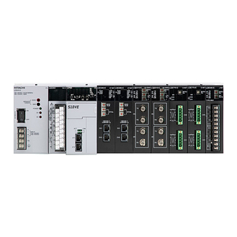
Hitachi S10VE Manuals
Manuals and User Guides for Hitachi S10VE. We have
1
Hitachi S10VE manual available for free PDF download: User Manual
Hitachi S10VE User Manual (506 pages)
Brand:
Hitachi
| Category:
Controller
| Size: 6.34 MB
Table of Contents
Table of Contents
32
1 Usage Notes
54
Figure 1-1 Installation Example
54
Figure 1-2 Wiring of Output Module
55
Figure 1-3 Grounding Example
55
Figure 1-4 Power Supply Voltage and Waveform
56
Figure 1-5 Grounding Method
57
2 Overview
60
Overview of the System
60
System Configuration
60
Example System Configuration
60
Figure 2-1 Example System Configuration
60
CPU Unit Configuration
61
Figure 2-2 Configuration of CPU Unit
61
Configuration of Remote I/O Communication
62
Figure 2-3 Configuration of Remote I/O Communication
62
System Components
64
Components of CPU Unit
64
Table 2-1 List of CPU Unit Components
64
PI/O Units and Peripherals
66
Padt
66
3 Specifications
68
Table 3-1 General Specifications
68
Table 3-2 Mount Base Specifications
69
Table 3-3 Power Supply Module Specifications
69
Table 3-4 CPU Module Specifications
70
Table 3-5 RI/O-IF Module Specifications
73
Table 3-6 Primary Battery Specification
74
4 Using the S10VE System
76
5 Part Names and Functions
78
Mount Base (HSC-1770)
78
Figure 5-1 External Dimensions of 7-Slot Mount Base
78
Table 5-1 Names and Functions of 7-Slot Mount Base Parts
79
Power Supply Module (LQV410)
80
Figure 5-2 External Dimensions of Power Supply Module
80
Table 5-2 Names and Functions of Power Supply Module Parts
80
CPU Module (LQP600)
82
Figure 5-3 External Dimensions of CPU Module
82
Figure 5-4 Names of Parts Inside Switch Cover of CPU Module
82
Table 5-3 Names and Functions of CPU Module Parts
83
Table 5-4 CPU RUN/STOP Switch and LADDER RUN/STOP Switch
83
Table 5-5 Combination Settings of the et St.no. (Ethernet Station Number Setting) Switch
84
Table 5-6 LED Specifications
84
Figure 5-5 Rear View of the CPU Module
85
RI/O-IF Module (LQE950)
86
Figure 5-6 External Dimensions of RI/O-IF Module
86
Table 5-7 Names and Functions of RI/O-IF Module Parts
86
Figure 5-7 Terminal Block Arrangement of RI/O-IF Module
87
Table 5-8 Terminal Signal Names and Functions
87
6 Installation
88
Operating Environment
88
Grounding
88
Figure 6-1 Example of Panel Grounding
88
Grounding the Cabinets
89
Figure 6-2 Connecting Cabinets to Ground (Multiple Cabinets in a Row)
89
Figure 6-3 Example of Base Insulation
89
Mounting Clearances
91
Figure 6-4 Unit Mounting Clearances
91
External Dimensions of Mount Base
92
Figure 6-5 External Dimensions of S10VE
92
Attaching the Mount Base
93
Figure 6-6 Attaching the Mount Base
93
Attaching Modules
94
Figure 6-7 Attaching a Module
94
Connecting the Primary Battery
96
Figure 6-8 Primary Battery Connection Procedure
96
Mounting Modules
97
Figure 6-9 External View of Mount Base
97
Restrictions on Mounting Option Modules
98
Table 6-1 Restrictions on Number of Option Modules
98
Restrictions on Mounting PI/O Modules to the CPU Unit
99
Table 6-2 Restrictions on Number of PI/O Modules
101
Current Consumption Calculation Table
102
Table 6-3 Current Consumption Calculation Table
102
7 Wiring
104
Cable Specifications
104
Table 7-1 Cable Specifications
105
Table 7-2 Recommended Cables
105
Wiring Standards
106
Terminal Block and Solderless Terminals
106
Figure 7-1 18-Point Terminal Block
106
Figure 7-2 11-Point Terminal Block
106
Figure 7-3 4-Point Terminal Block
107
Figure 7-4 Compatible Solderless Terminal
107
Figure 7-5 Connecting Solderless Terminals to Cables
107
Attaching the Terminal Block
108
Power Supply Wiring
109
Figure 7-6 Power Supply Wiring (with Insulating Transformer Installed on Power Distribution Panel)
109
Figure 7-7 Power Supply Wiring (with Insulating Transformer Installed on S10VE Panel (Pcs Panel))
109
Figure 7-8 Example of Internal Panel Wiring
110
Ground Wiring
111
Figure 7-9 Example of Ground Wiring
111
Table 7-3 List of Ground Wiring Requirements
112
Wiring the Power Supply Module
113
Figure 7-10 Wiring of Power Supply Module
113
Figure 7-11 Input Terminal Connection Diagram
113
Figure 7-12 Power Module Wiring in High-Noise Environment
114
Wiring for External I/O Signals of the RI/O-IF Module
115
Wiring for Pcsok Signal
115
Figure 7-13 Wiring for Pcsok Signal
115
Wiring for RI/O STOP and CPU STOP/RUN Signals
116
Figure 7-14 Wiring of RI/O STOP and CPU STOP/RUN Signals
116
Wiring for Remote I/O
117
Connecting the Remote I/O Cables
117
Figure 7-15 Wiring of Remote I/O Cables
117
Examples of Improper Remote I/O Wiring
118
Table 7-4 Correct and Incorrect Remote I/O Wiring
118
Examples of Cable Wiring
119
Figure 7-16 Wiring Example When Using Cables with Different Characteristics
119
Figure 7-17 Wiring Example When Using HSC-1000 and HSC-2100 Series Remote I/O Stations in
120
Setting Terminating Resistance
121
Table 7-5 Setting Terminating Resistance
121
Connecting the Remote I/O Cable Shields
123
Figure 7-18 Example of Connections Within the same Panel
123
Figure 7-19 Examples of Connections between Panels Installed in a Row
124
Figure 7-20 Example of Connections between Different Panels
125
Figure 7-21 Example of Connections in the same Panel and between Different Panels
125
Wiring the Ethernet Cabling
126
Circuit Classifications and Examples of Duct Wiring
126
Circuit Classifications for Wiring
126
Figure 7-22 Wiring the Ethernet Cabling
126
Table 7-6 Circuit Classifications
126
Example of Duct Wiring
127
Figure 7-23 Example of Wiring Ducts Carrying Cables for Different Circuit Classifications (Top View)
127
Working with Connector Caps
128
Figure 7-24 Positions of Connector Caps on CPU Module During Shipping
128
Figure 7-25 Positions of Connector Caps on Mount Base During Shipping
128
8 Tools
130
Notes on Tool Usage
130
Overview of Tools
130
Hardware and Software Requirements
130
Restrictions on Connection Configuration of PADT and S10VE
130
Table 8-1 Types of Tool
130
Constructing the System
131
Constructing a New System
131
Replacing the CPMS
133
Installing the Tools
134
Notes on Installation
134
Figure 8-1 User Account Control Message
135
Figure 8-2 Installshield Wizard Window
135
Installing Individual Tools
135
Figure 8-3 Installshield Wizard Complete Window
136
Figure 8-4 "Are You Sure You Want to Uninstall the Selected Application and All of Its Components?" Message
137
Figure 8-5 Uninstall Complete Message (for Uninstallation with Tool Not Running)
137
Uninstalling Individual Tools
137
Figure 8-6 Uninstall Complete Message (for Uninstallation of Running Tool)
138
Figure 8-7 Error Message Displayed by RPDP Internal Command
138
Reinstalling Individual Tools
139
Figure 8-8 User Account Control Message (Basic Installation Set)
140
Figure 8-9 Setup Window (Basic Installation Set)
140
Installing and Uninstalling Tools from the Basic Installation Set
140
Starting the System
142
Starting Tools
142
Figure 8-10 Screen Displayed When BASE SYSTEM Starts
142
Starting BASE SYSTEM
142
Figure 8-11 Screen Displayed When LADDER DIAGRAM SYSTEM Starts
144
Starting LADDER DIAGRAM SYSTEM
144
Figure 8-12 Screen Displayed When HI-FLOW SYSTEM Starts
145
Starting HI-FLOW SYSTEM
145
Figure 8-13 Setting Tool Window
146
Starting the Setup Tools
146
Exiting Tools
147
Exiting BASE SYSTEM
147
Exiting Setup Tools
147
Exiting the LADDER and HI-FLOW Systems
147
Base System
148
Layout of the BASE SYSTEM Main Window
148
Figure 8-14 Layout of the BASE SYSTEM Main Window
148
Main Menu
148
Figure 8-15 Status Bar
149
Status Bar
149
Project Functions
150
Figure 8-16 Window after Clicking the Project Menu
150
Figure 8-17 Properties Window
151
Figure 8-18 Save Confirmation Message
151
Project Menu: New
151
Figure 8-19 Error Message When RPDP Is Not Installed
152
Figure 8-20 Error Message Indicating Lack of Site Creation Permission
152
Figure 8-21 Overwrite Confirmation Message
153
Figure 8-22 Error Message Indicating that C-Mode Usage Setting Cannot be Changed
153
Figure 8-23 Message Asking Whether You Want to Create a Project with an Existing Pcs Number
154
Figure 8-24 Error Message Indicating Lack of Site Deletion Permission
154
Figure 8-25 Error Message Indicating Lack of Site Update Permission
155
Figure 8-26 Project List Window (Opening a Project)
156
Project Menu: Open
156
Figure 8-27 Error Message Indicating Lack of Site Usage Permission
157
Project Menu: Close
157
Figure 8-28 Project List Window (Deleting a Project)
158
Project Menu: Delete
158
Figure 8-29 Deletion Confirmation Message
159
Project Menu: Set Network
160
Figure 8-30 Set Network Window
161
Network Configuration of CPU Built-In Ethernet
161
Figure 8-31 Message Asking for Confirmation of Ethernet Station Number Overwrite
162
Figure 8-32 Reset Confirmation Message
163
Figure 8-33 Reset Successful Message
163
Figure 8-34 Reset Failed Message
164
Figure 8-35 Set Network (ET.NET) Window
165
NET Configuration
165
Figure 8-36 Route Information Window
166
Figure 8-37 Option Module Parameter Setup List Window
166
Figure 8-38 Overwrite Confirmation Message
167
Figure 8-39 Message Confirming Removal of Duplicate Settings
167
Figure 8-40 Reset Confirmation Message
168
Figure 8-41 Reset Successful Message
168
Figure 8-42 Reset Failed Message
168
Figure 8-43 Open Window (Set Network (ET.NET))
169
Figure 8-44 File Open Window
170
Figure 8-45 Wrong File Selected Message
170
Figure 8-46 Option Module Parameter Setup List Window (Deletion)
171
Figure 8-47 Confirm Deletion Message
171
Figure 8-48 Save as Dialog Box
172
Figure 8-49 File Save Window
173
Figure 8-50 Error Message When Connected to ET.NET Module
176
Figure 8-51 Download CPMS Window
176
Figure 8-52 Error Message When CPU Switch Is Set to STOP
176
Project Menu: Download CPMS
176
Figure 8-53 Progress Window (Download)
177
Figure 8-54 Confirmation of ROM Load Re-Execution Message
177
Figure 8-55 ROM Load Failure Error Message
178
Figure 8-56 Reset Confirmation Message (End)
179
Figure 8-57 Error Message When User Does Not Have Operation Log Write Permission
179
Project Menu: End
179
Online Functions
180
Figure 8-58 Window after Clicking the Online Menu
180
Table 8-3 List of Online Menu Items
180
Figure 8-59 Change Pcs Window
181
Figure 8-60 Message When Pcs Connection Is Successful
181
Online Menu: Change Pcs
181
Figure 8-61 Pcs Status Window
182
Online Menu: Display Pcs STATUS and Change Pcs STATUS
182
Figure 8-62 Data Send/Receive (Option Module) Window
187
Online Menu: Data Send/Receive
187
Figure 8-63 Open Window (Data Send/Receive)
188
Figure 8-64 Send Data Window
188
Sending Data
188
Figure 8-65 Error Message Displayed When Pcs Numbers Do Not Match
189
Figure 8-66 Error Message Displayed When Module Identification Codes Do Not Match
189
Figure 8-67 Error Message Displayed When Module Numbers Do Not Match
189
Figure 8-68 Progress Window (Sending Data)
190
Figure 8-69 Save as Window (Data Send/Receive)
191
Figure 8-70 Receive Data Window
191
Receiving Data
191
Figure 8-71 Progress Window (Receiving Data)
192
Comparing Data
193
Figure 8-72 Compare Data Window
193
Figure 8-73 Progress Window (Comparing Data)
193
Figure 8-74 Message Indicating that Comparison was Successful
194
Figure 8-75 Overwrite Confirmation Message
194
Figure 8-76 Message Indicating Inconsistent Data (First Format)
194
Figure 8-77 Message Indicating Inconsistent Data (Second Format)
194
Figure 8-78 Format of Comparison Error Data File
195
Deleting Data
196
Figure 8-79 Data Deletion Confirmation Message
196
Figure 8-80 Remote Reset Confirmation Message
197
Online Menu: Backup, Restore, Backup Save Data Comparison
197
Online Menu: Remote Reset
197
Figure 8-81 Remote Restart Confirmation Message
198
Figure 8-82 Restart Successful Message
198
Figure 8-83 Restart Failed Message
198
Online Menu: Remote Restart
198
Figure 8-84 Data Clear Confirmation Message
199
Online Menu: Data Clear
199
Table 8-4 Data Clear Area
199
Figure 8-85 Error Detected Message
200
Program Functions
201
Figure 8-86 Window after Clicking the Program Menu
201
Table 8-5 List of Program Menu Items
201
Figure 8-87 Setting Tool Window
202
Program Menu: HI-FLOW
202
Program Menu: LADDER
202
Program Menu: Setting Tool
202
Figure 8-88 Error Message Displayed When Selected Tool Cannot be Run
203
Table 8-6 Items Displayed in Setting Tool Window
203
Setting Functions
204
Figure 8-89 Window after Clicking the Setting Menu
204
Table 8-7 List of Setting Menu Items
204
Figure 8-90 Set Time Window
205
Setting Menu: Set Time
205
RAS Functions
206
Figure 8-91 Window after Clicking the RAS Menu
206
Table 8-8 List of RAS Menu Items
206
Figure 8-92 Module List Window
207
RAS Menu: Module List
207
Table 8-9 Items in Module List Window
207
Figure 8-93 Display Error Log CP Window
208
Figure 8-94 Display Error Log HP Window
208
RAS Menu: Error Log Display
208
Table 8-10 Module Names that Can be Selected in Display Error Log CP Window
209
Table 8-11 Items Displayed in Display Error Log CP and HP Windows
209
Displaying Error Log Details
212
Figure 8-95 Error Log Detail Window
212
Figure 8-96 MCS Window
214
Figure 8-97 Rewrite Memory in RUN Mode Confirmation Message
214
RAS Menu: MCS
214
Figure 8-98 Performance Window
216
RAS Menu: Display Performance
216
Figure 8-99 Event Register Monitor Window
218
RAS Menu: Event Register
218
Figure 8-100 Display Status of Network Window
219
RAS Menu: Network Information
219
Table 8-12 Items in Selection of the Network Drop-Down List
219
Figure 8-101 Save as Window
220
Table 8-13 Tabbed Pages in Display Status of Network Window
220
Figure 8-102 Display Ethernet Communication of Trace Log (LADDER) Window
221
RAS Menu: Ethernet Communication of Trace Log
221
Table 8-14 Information in Ethernet Communication Trace Log (LADDER)
221
Figure 8-103 Display Ethernet Communication of Trace Log (Socket Handler) Window
222
Table 8-15 Information in Ethernet Communication Trace Log (Socket Handler)
222
Figure 8-104 Save as Window
223
Figure 8-105 DHP Information Window
224
RAS Menu: DHP Information
224
Figure 8-106 Display DHP Trace CP Side Window
225
Figure 8-107 Autosave Window
226
Figure 8-108 Error Message When CPU Is in RUN Mode
226
Figure 8-109 Atdmpbs Command Error Message
226
RAS Menu: Autosave
226
Figure 8-110 Executing Window
227
Figure 8-111 Processing Completed Message
227
Figure 8-112 Structure of Autosave File
228
Figure 8-113 Format of Fault Analysis Information File
229
CPMS Debugger Functions
239
Figure 8-114 Window after Clicking the CPMS Debugger Menu
239
Table 8-16 List of CPMS Debugger Menu Items
239
CPMS Debugger Menu: Task Abort
240
Figure 8-115 Task Abort Window
240
Figure 8-116 Task Abort Confirmation Message
240
CPMS Debugger Menu: Display Task Status
241
Figure 8-117 Task Status Window
241
Table 8-17 Information in Task Registration Area
241
Table 8-18 Task Statuses
242
CPMS Debugger Menu: Initialize Task
243
Figure 8-118 Initialize Task Window
243
Figure 8-119 Error Message When CPMS Is Not Downloaded
243
Figure 8-120 Error Message Displayed When Data Cannot be Read
244
Figure 8-121 Progress Window (Initializing Task Environment)
244
Backup Restore System
246
Backup
246
Figure 8-122 CPU Stop Confirmation Message for Backup Function
246
Figure 8-123 Backup Window
247
Figure 8-124 Browse for Folder Dialog Box
247
Figure 8-125 Overwrite Confirmation Message
248
Figure 8-126 State of Backup Window (When Receiving Data)
248
Figure 8-127 Backup Cancelation Confirmation Message
249
Figure 8-128 CPU RUN Confirmation Message
249
Figure 8-129 State of Backup Window (When Backup Is Canceled)
249
Figure 8-130 STOP Recovery Guidance Message
250
Figure 8-131 State of Backup Window (When Comparing Data)
250
Figure 8-132 Data Comparison Cancelation Confirmation Message
251
Figure 8-133 State of Backup Window (When Data Comparison Is Canceled)
251
Figure 8-134 State of Backup Window (When no Inconsistencies Are Found)
252
Figure 8-135 State of Backup Window (When Inconsistencies Are Found)
252
Figure 8-136 Format of Compare_Error.txt File
253
Restore
255
Figure 8-137 CPU Stop Confirmation Message for Data Restoration
255
Figure 8-138 Restore Window
256
Figure 8-139 Message Asking Whether to Continue Restoration
257
Figure 8-140 State of Restore Window (When Sending Data)
257
Figure 8-141 State of Restore Window (When Comparing Data)
257
Figure 8-142 Confirmation Message for Pcs Number Change
258
Figure 8-143 Window for Changing Pcs Number of Restored Pcs
258
Figure 8-144 CPU RUN Confirmation Message
259
Figure 8-145 STOP Recovery Guidance Message
259
Figure 8-146 State of Restore Window (When no Inconsistencies Are Found)
260
Figure 8-147 State of Restore Window (When Inconsistencies Are Found)
260
Figure 8-148 Confirmation Message for Overwriting Comparison Error Data File
261
Backup Save Data Comparison
262
Figure 8-149 CPU Stop Confirmation Message for Backup Data Comparison
262
Figure 8-150 Backup Save Data Comparison Window
263
Figure 8-151 Message Asking Whether to Continue Backup Data Comparison
264
Figure 8-152 State of Backup Save Data Comparison Window (During Data Comparison)
264
Figure 8-153 Confirmation Message When Canceling Backup Data Comparison
264
Figure 8-154 State of Backup Save Data Comparison Window (When Data Comparison Is Canceled)
265
Figure 8-157 Confirmation Message for Overwriting Comparison Error Data File
266
Duration of Backup/Restoration Processes
268
Table 8-19 Measured Backup/Restoration Times
268
Scope of Backup, Restoration, and Comparison
269
Table 8-20 Scope of Backup
269
Figure 8-158 Areas Subject to ROM Load Operation
270
Table 8-21 Scope of Restoration
271
Table 8-22 Area Excluded from Backup Data Comparison
271
Other Functions
272
Operation History Recording Function
272
Figure 8-159 Format of Operation Record File
272
Table 8-23 Items in Operation Record File
273
Contents of CPMS Files
276
Table 8-24 List of CPMS File Contents
276
Error Messages
277
Common
277
Table 8-25 Common Error Messages
277
Project Menu
279
Table 8-26 Project - New
279
Table 8-27 Properties Window
279
Table 8-28 Project List Window (Open)
280
Table 8-29 Project List Window (Delete)
281
Table 8-30 Close
281
Table 8-31 Set Network Window
281
Table 8-32 Download CPMS Window
282
Table 8-33 End
283
Online Menu
284
Table 8-34 Change Pcs Window
284
Table 8-35 Display Pcs STATUS and Change Pcs STATUS
285
Table 8-36 Data Send/Receive Window
285
Table 8-37 Backup, Restore, and Backup Save Data Comparison
286
Table 8-38 Data Clear
287
Program Menu
288
Setting Menu
288
Table 8-39 Program Menu
288
Table 8-40 Setting Tool Window
288
Table 8-41 Set Time Window
288
RAS Menu
289
Table 8-42 Error Log
289
Table 8-43 Performance Window
289
Table 8-44 DHP Information Window
289
CPMS Debugger Menu
290
Table 8-45 Task Abort Window
290
Table 8-46 Initialize Task Window
291
RPC Error Messages
292
Table 8-47 RPC Error Messages
292
Error Codes
293
Table 8-49 Svaddsite
294
Table 8-50 Svupdatesiteos
294
Table 8-51 Svsitedel
294
9 Settings
296
Setting Items
296
Table 9-1 Hardware Settings
296
Table 9-2 Software Settings
297
I/O Number Structure and Scope of Allocation
299
Setting PI/O and Remote I/O
300
PI/O Installation Setting
300
Partition Setting (FIX/FREE)
301
Table 9-3 FIX and FREE Settings
302
Output Hold Setting for Digital Output Modules
303
I/O Point Number Setting
303
Table 9-4 CPU Unit I/O Number Allocation and I/O Points Used (Partition Setting: FREE, First I/O Number: 0000)
304
Table 9-5 CPU Unit I/O Number Allocation and I/O Points Used (Partition Setting: FIX, First I/O Number: 0000)
305
Ladder Synchronous/Asynchronous Mode Setting
306
Remote I/O Optical Adapter Connection Setting
307
Remote I/O Point Setting
307
Analog Module and Pulse Counter Module Settings
308
10 Indicator
310
Overview
310
Figure 10-1 Indicator and Menu Keys
310
Table 10-1 Names and Functions of Indicator and Menu Keys
310
Information Displayed on Indicator
311
Table 10-2 Information Displayed on Indicator
311
Indicator Display Transitions
312
Figure 10-2 Indicator Display Transitions When CPU Module Is in STOP Mode
312
Figure 10-3 Indicator Display Transitions When CPU Module Is in RUN Mode
313
Explanation of Displayed Information
314
Home Position Display
314
Figure 10-4 Display Transitions at Home Position
314
Table 10-3 CPU Module Status Display
314
Table 10-4 Minor Error Status Display
315
Table 10-5 Option Module Error Display
315
Table 10-6 Serious Error Code Display
315
Firmware Version Display
316
OS Version Display
316
CPU Module Error Status Display
317
Figure 10-5 Display Transitions of CPU Module Error Status
317
Table 10-7 CPU Module Error Status Display
318
Indicator Pattern Display (Available When CPU Module Is in STOP Mode)
319
Figure 10-6 Display Transitions of Indicator Patterns
319
Ladder Mode Display (Extended Menu)
320
Table 10-8 Indicator Patterns
320
Table 10-9 Ladder Mode Display
320
Pcs Number Display (Extended Menu)
321
Display of E Coils in on Mode (Extended Menu)
321
Figure 10-7 Display Transitions of E Coils in on States
321
11 Operation
322
Starting and Stopping the CPU Module
322
User Program Operations
323
Figure 11-1 User Program Operation (Ladder and HI-FLOW Individual Use)
323
Figure 11-2 User Program Operation (Ladder and HI-FLOW Simultaneous Use)
323
Figure 11-3 Operation When the Sequence Cycle Is Longer than the Program Processing Time
324
Figure 11-4 Operation When the Sequence Cycle Is Shorter than the Program Processing
324
Remote I/O Operation
325
Remote I/O Connection Configuration
325
Figure 11-5 Remote I/O Connection Configuration
325
Synchronous and Asynchronous Ladder Operation
326
Figure 11-6 Synchronous and Asynchronous Ladder Operation
326
Processing Time
327
Figure 11-7 Processing Time Concept
327
Table 11-2 Overview of the Transmission Time Required for One Cycle (One Scan)
327
Remote I/O Transfer Points and Transfer Areas
329
Figure 11-8 Remote I/O Transfer Point Settings
329
Output Operations of the Digital Output Module
330
Figure 11-9 Output Operation of the Digital Output Module
330
List of States and State Transitions
331
List of States
331
Table 11-3 S10VE State List
331
State Transitions
332
Figure 11-10 S10VE State Transitions
332
Backup Functionality
333
Clock Functionality
334
System Register for Clock Control
334
Setting the Clock by Using Ladder Programs
336
Figure 11-11 Example Ladder Program for Setting the Clock
336
Updating the Date
337
State Signal Timing
338
Pcsok Signal
338
Figure 11-12 Output Timing of the Pcsok Signal (from STOP to RUN)
338
Figure 11-13 Output Timing of the Pcsok Signal (from RUN to STOP)
338
Ladder Program RUN/STOP Signal
339
Figure 11-14 Timing of the STOP/RUN Input Signal (from off to ON)
339
Figure 11-15 Timing of the STOP/RUN Input Signal (from on to OFF)
339
RI/O STOP Input Signal
340
Figure 11-16 Timing of the RI/O STOP Input Signal (from off to ON)
340
Figure 11-17 Timing of the RI/O STOP Input Signal (from on to OFF)
340
12 Inspection
342
Limited-Life Components and Replacement Cycle
342
Table 12-1 Limited-Life Components and Replacement Cycle
342
Periodic Check Items
343
Table 12-2 Check Items
343
13 Troubleshooting
346
Figure 13-1 Troubleshooting Procedure
346
Troubleshooting Via Visual Confirmation of Leds and Indicators
347
Power Supply Module (Model: LQV410)
347
Table 13-1 Diagnosing Problems by Visually Confirming the Power Supply Module Leds
347
CPU Module (Model: LQP600)
348
Table 13-2 Diagnosing Problems by Visually Confirming the CPU Module Leds
348
Table 13-3 CPU Module Troubleshooting
349
Table 13-4 OD.RING Module Troubleshooting
351
Table 13-5 FL.NET Module Troubleshooting
352
Table 13-6 J.NET Module Troubleshooting
355
Table 13-7 D.NET Module Troubleshooting
356
Table 13-8 ET.NET Module Troubleshooting
357
Troubleshooting Individual Modules
359
CPU Module Troubleshooting
359
Table 13-9 Troubleshooting Transient Hardware Failures
359
Table 13-10 User Program Troubleshooting
362
Troubleshooting Optional Modules
365
OD.RING Module Troubleshooting
365
Table 13-11 Troubleshooting from the Transmission LED (TX) and the Reception LED (RX)
365
Table 13-12 Troubleshooting from Sent and Received Data
366
Figure 13-2 Error Freeze Information Format
368
Table 13-13 Error Codes
369
Figure 13-4 Trace Buffer
371
Figure 13-5 Trace Control Table
372
Figure 13-8 Trace Data
374
Figure 13-9 Frame Header Block
374
Table 13-14 Trace Events and Processing
375
Figure 13-10 Trace Cause
376
Figure 13-11 Transmission Error Status
376
Figure 13-12 Reception Error Status
377
Table 13-15 Error Status Details
377
J.NET Module Troubleshooting
378
Table 13-16 Troubleshooting from the Transmission LED (TX) and the Reception LED (RX)
378
Table 13-17 Troubleshooting from Sent and Received Data
379
Figure 13-13 Error Freeze Information
380
Table 13-18 J.NET Module Troubleshooting
382
Table 13-19 Error Codes for Communication Errors
383
Table 13-20 Error Codes for Errors Detected by a Station
384
Table 13-21 Polling Error Codes
384
Figure 13-15 Address of the Error Accumulation Counters
385
Figure 13-16 Structure of the Trace Area
386
Figure 13-17 Structure of the Trace Data Area
387
D.NET Module Troubleshooting
388
Table 13-22 Troubleshooting from the LED Status
388
Table 13-23 Causes of D.NET Module Communication Failures
389
Table 13-24 D.NET Module Troubleshooting
390
FL.NET Module Troubleshooting
391
Table 13-25 FL.NET Module Troubleshooting
391
Table 13-26 Network Failures and Corrective Actions (When Communication Is Unstable)
392
Figure 13-18 Troubleshooting Procedure
395
NET Module Troubleshooting
395
Figure 13-19 Failed Parts in an Example System Configuration
396
Table 13-28 Error Codes Reported to the CPU Module from the ET.NET Module
401
Table 13-29 Internal ET.NET Module Error Codes
405
Table 13-30 Ethernet Communication Trace Log Information (for Ladder)
408
Table 13-31 Ethernet Communication Trace Log Information (for Socket Handler)
409
Table 13-32 DHP Trace Information
410
Table 13-33 Count Information
421
Remote I/O Communication Troubleshooting
429
Figure 13-20 Troubleshooting Procedure for the PI/O Unit
429
Troubleshooting Procedure
429
Figure 13-21 Troubleshooting Procedure for the Remote I/O Line
430
Figure 13-22 Troubleshooting Procedure for Intermittent Timeouts
431
Detailed Check Items
433
Table 13-34 Check Items for When a Failure Occurs Repeatedly
433
Figure 13-23 Example Station Module Connection Configuration
434
Table 13-35 Analyzing Failures from the Station Module Leds
434
Figure 13-24 Remote I/O Optical Adapter Failure Locations
435
Table 13-36 Analyzing Failures from Remote I/O Optical Adapter Leds
435
Figure 13-25 Example Station Module Connection Configuration
436
Table 13-37 Check Items for When a Failure Occurs Intermittently
436
Figure 13-26 Example Remote I/O Optical Adapter Failure Location
437
System Register
438
Table 13-40 Register Used to Check the Remote I/O Line Status
438
Table 13-41 System Register Details
439
Figure 13-27 Example System Configuration
440
Relationship between the System Configuration and System Register
440
Table 13-42 System Register
441
PI/O Module Troubleshooting
442
Analog Module Troubleshooting
442
Table 13-43 Analog Input Module Troubleshooting
442
Table 13-44 Analog Output Module Troubleshooting
443
Digital Module Troubleshooting
444
Table 13-45 Digital Input Module Troubleshooting
444
Autosave Procedure
445
If the CPU Module Is Connected to PADT
445
If the CPU Module Is Not Connected to PADT
445
14 Adding and Replacing Modules
446
Power Supply Module (LQV410)
446
Removing the Power Supply Module
447
Figure 14-1 Parts of Power Supply Module Involved in Replacement Process
447
Installing a Power Supply Module
448
CPU Module (LQP600)
449
Replacing the CPU Module
449
Figure 14-2 Parts Involved in CPU Module Replacement Process
449
Removing the CPU Module
450
Replacing the Primary Battery
451
Figure 14-3 Diagram of Primary Battery Replacement
453
RI/O-IF Module (LQE950)
454
Removing the RI/O-IF Module
454
Installing a RI/O-IF Module
454
Figure 14-4 Parts Involved in RI/O-IF Module Replacement Process
454
OD.RING Module (LQE510-E)
455
Removing the OD.RING Module
455
Installing an OD.RING Module
456
Figure 14-5 Parts Involved in Replacement or Addition of OD.RING Module
456
Adding an OD.RING Module
457
J.NET Module (LQE540-E)
458
Removing the J.NET Module
458
Installing a J.NET Module
459
Figure 14-6 Parts Involved in Replacement or Addition of J.NET Module
459
Adding a J.NET Module
460
D.NET Module (LQE770-E)
461
Removing the D.NET Module
461
Installing a D.NET Module
462
Figure 14-7 Parts Involved in Replacement or Addition of D.NET Module
462
Adding a D.NET Module
463
FL.NET Module (LQE702-E)
464
Removing the FL.NET Module
464
Installing an FL.NET Module
465
Figure 14-8 Parts Involved in Replacement or Addition of FL.NET Module
465
Adding an FL.NET Module
466
NET Module (LQE260-E)
467
Removing the ET.NET Module
467
Installing an ET.NET Module
468
Figure 14-9 Parts Involved in Replacement or Addition of ET.NET Module
468
Adding an ET.NET Module
469
PI/O Module
470
Removing a PI/O Module
470
Installing a PI/O Module
471
Adding a PI/O Module
471
Remote I/O Optical Adapter Module (LQZ410)
472
Removing the Remote I/O Optical Adapter Module
472
Installing a Remote I/O Optical Adapter Module
473
Backup and Restoration
474
Backup Procedure
474
Restoration Procedure
474
Disposal
474
Hitachi Programmable Controller S10VE Repair Request
476
List of Error Codes
478
Table B-1 List of CPU Module Error Codes
478
Table B-2 List of OD.RING Module Error Codes
481
Table B-3 List of J.NET Module Error Codes
482
Table B-4 List of D.NET Module Error Codes
484
Table B-5 List of FL.NET Module Error Codes
485
Table B-6 List of ET.NET Module Error Codes
487
Replacing Software Products in BASE SET/S10VE
490
Preface
490
Cautionary Notes
490
Cautionary Notes on CPMS/S10VE
491
Overview of Software Product Replacement Procedure
492
Checking Version and Revision Numbers of Installed Software Products
494
Uninstalling Software Products
495
Installing Software Products and Checking the Installed Version and Revision Numbers
497
Replacing CPMS/S10VE in Existing Projects
499
Setting the Connection-Target Pcs
501
Checking Current Version and Revision Numbers of CPMS/S10VE on Actual Machines
502
Downloading a New Version of CPMS/S10VE to an Actual Machine
503
Checking Version and Revision Numbers of the New CPMS/S10VE Downloaded to the Actual Machine
504
Advertisement
Advertisement
Related Products
Hitachi SPX-WDC5
Hitachi SJ-P1 Series
Hitachi S10mini LQS070
Hitachi S10 Series
Hitachi S10V Series
Hitachi WALL SUPPORT
Hitachi STAND SUPPORT
Hitachi S1-00125HFEF
Hitachi S1-01700HFEF
Hitachi S1-06000HFEF
Hitachi Categories
Projector
Air Conditioner
Drill
Power Tool
TV
More Hitachi Manuals
Login
Sign In
OR
Sign in with Facebook
Sign in with Google
Upload manual
Upload from disk
Upload from URL