Sign In
Upload
Manuals
Brands
HP Manuals
Measuring Instruments
8711C
HP 8711C Manuals
Manuals and User Guides for HP 8711C. We have
1
HP 8711C manual available for free PDF download: User Manual
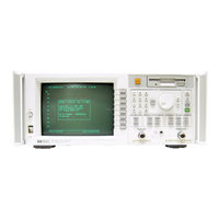
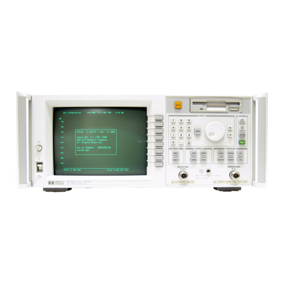
HP 8711C User Manual (530 pages)
RF Network Analyzers
Brand:
HP
| Category:
Measuring Instruments
| Size: 6.85 MB
Table of Contents
Table of Contents
6
1 Installing the Analyzer
18
Step 1. Check the Shipment
20
Step 2. Meet Electrical and Environmental Requirements
21
Voltage Selector Switch Location
21
Protective Earth Ground
23
Ventilation Clearance Requirements
24
Step 3. Check the Analyzer Operation
26
Step 4. Configure the Analyzer
27
Connecting Peripherals and Controllers
28
Analyzer Rear Panel Line Module and Selected Connectors
28
HP-IB Connection Configurations
30
L-L. Maximum HP-IB Cable Lengths
31
Installing the Analyzer in a Rack
34
Preventive Maintenance
35
Maximum and Minimum Protrusion of Center Conductor from Mating Plane
35
2 Getting Started
36
Network Analyzer Front Panel Features
37
Front Panel Tour
38
Entering Measurement Parameters
39
Connect the Filter to the Analyzer
40
Both Measurement Channels Active
46
Split Display
47
Performing the Operator's Check
48
Equipment List
49
Make a Transmission Measurement
50
Equipment Setup for Transmission Measurement
50
Verify Transmission Measurement
51
Make a Reflection Measurement
52
Verify Reflection Measurement
52
Connect the Load
53
If the Analyzer Fails the Operator's Check
54
3 Making Measurements
55
Measuring Devices with Your Network Analyzer
57
DUT Response to an RF Signal
57
Simplified Block Diagram
59
Block Diagram
61
When to Use Attenuation and Amplification in a Measurement Setup
63
When to Change the System Impedance
64
The Typical Measurement Sequence
65
Using the BEGIN Key to Make Measurements
66
Key Overview
67
Using the [BEGIN) Key to Configure Measurements . . . the User BEGIN Function (Option Lc2 Only)
69
Measuring Transmission Response
72
Enter the Measurement Parameters
72
Calibrate for a Transmission Response Measurement
73
Connect the DUT
75
Equipment Setup for a Transmission Response Measurement
75
View and Interpret the Transmission Measurement Results
76
Example of a Transmission Measurement Display
77
Measuring Reflection Response
78
Enter the Measurement Parameters
78
Calibrate for a Reflection Response Measurement
79
Equipment Setup for a Reflection Response Calibration
80
Connect the DUT
81
Equipment Setup for a Reflection Measurement of a Two-Port
81
Equipment Setup for a Reflection Measurement of a One-Port
81
View and Interpret the Reflection Measurement Results
82
Example of a Reflection Measurement Display
83
Making a Power Measurement Using Broadband Detection
84
Enter the Measurement Parameters
85
Connect the DUT
86
Equipment Setup for a Power Measurement
86
View and Interpret the Power Measurement Results
87
Example of a Power Measurement
88
Measuring Conversion Loss
89
Filtering out the Unwanted Mixing Product
90
Enter the Measurement Parameters
91
Perform a Normalization Calibration
92
Connect the DUT
93
Equipment Setup for a Conversion Loss Measurement
93
View and Interpret the Conversion Loss Results
94
Example of a Conversion Loss Measurement
95
Measuring am Delay (Option 1DA or 1DB)
97
Enter the Measurement Parameters
97
Calibrate for an am Delay Measurement
98
View and Interpret the am Delay Results
100
Example of an am Delay Measurement
101
Making Measurements with the Auxiliary Input
102
Auxiliary Input Characteristics
102
4 Using Instrument Functions Using Markers
106
To Activate Markers
107
To Turn Markers off
108
To Use Marker Math Functions
122
To Use Delta (A) Marker Mode
128
To Use Other Marker Functions
130
Using Limit Testing
131
To Create a Flat Limit Line
132
To Create a Sloping Limit Line
134
To Create a Single Point Limit
136
To Use Marker Limit Functions
137
To Use Relative Limits
143
Other Limit Line Functions
144
Additional Notes on Limit Testing
146
Using Reference Tracking
149
To Track the Peak Point
150
Reference Positions
150
To Track a Frequency
151
Customizing the Display
152
Using the Split Display Feature
153
Enabling/Disabling Display Features
154
Modifying Display Annotation
156
Expanding the Displayed Measurement
161
Saving and Recalling Measurement Results
164
Saving Instrument Data
166
To Recall from a Disk or Internal Memory
170
Other File Utilities
171
To Use Directory Utilities
174
Formatting a Floppy Disk
176
Connecting and Configuring Printers and Plotters
177
Select a Compatible Printer or Plotter
178
Select an Appropriate Interface Cable
179
Connect the Printer or Plotter
180
Configure the Hardcopy Port
181
Define the Printer or Plotter Settings
184
Printing and Plotting Measurement Results
189
To Select the Copy Port
190
Define the Output
191
Using a Keyboard
195
To Connect the Keyboard
195
To Use the Keyboard to Edit
196
Front Panel Control Using a Keyboard
197
Using an External VGA Monitor
199
Customizing Color on an External Monitor
200
Synchronizing and Positioning the Display
202
5 Optimizing Measurements
203
Increasing Sweep Speed
205
To Increase the Start Frequency
205
To Set the Sweep Time to AUTO Mode
206
To Widen the System Bandwidth
206
To Reduce the Amount of Averaging
207
To Reduce the Number of Measurement Points
207
To View a Single Measurement Channel
208
To Turn off Alternate Sweep
209
To Turn off Markers and Marker Tracking
209
To Turn off Spur Avoidance
210
To Avoid Frequency Bandcrossings by Minimizing the Span (HP 8713C Only)
211
Increasing Network Analyzer Dynamic Range
212
To Increase the Receiver Input Power
212
To Reduce the Receiver Noise Floor
213
Reducing Trace Noise
215
To Activate Averaging for Reducing Trace Noise
215
To Change System Bandwidth for Reducing Trace Noise
216
Reducing Mismatch Errors
219
Reducing Mismatch Errors in a Reflection Measurement
219
Reducing Mismatch Errors in a Transmission Measurement
220
Reducing Mismatch Errors When Measuring both Reflection and Transmission
220
Measuring Devices with Long Electrical Delay
221
6 Calibrating for Increased Measurement Accuracy
222
Measurement Calibration Overview
224
Calibrating for Increased Measurement Accuracy Measurement Calibration Overview
225
The Calibration Reference Plane
226
Determine if a Calibration Is Necessary
228
When a Calibration Is Not Necessary
228
When a Calibration Is Necessary
228
Choose an Appropriate Calibration Method
229
To Perform a Normalization Calibration
231
To Perform a Transmission Calibration
232
To Perform a Reflection Calibration
234
To Perform a Conversion Loss Calibration
236
To Perform an am Delay Calibration (Option 1DA or 1DB Only)
237
To Perform a Calibration with Non-Standard Connectors
238
Writing or Editing Your Own Cal Kit File
240
Save the Calibration
246
Check the Calibration
247
Using Calibration Check for Analysis and Troubleshooting
247
To Perform a Calibration Check
248
Error Term Descriptions and Typical Values
249
7 Automating Measurements
258
Configuring Your Test System
262
Measurement System Topology
262
Expandability and Large Systems
269
Throughput Considerations
269
Selecting a Measurement Controller
270
Selecting a Programming Language
272
Operator Interaction
275
Prompting the Operator
277
Using Graphics to Create On-Screen Diagrams
278
Data Entry Using a Barcode Reader
286
Data Entry Using an External Keyboard
287
Using the Analyzer's Title Feature
288
Hot Keys on External Keyboard for Common Functions
289
User-Defined TTL Input/Output
291
Using a Foot Switch or Button Box
292
Limit Test Pass/Fail TTL Input/Output
294
Analyzer Port Numbers
296
Output for Large Screen External Monitor
297
Measurement Setup and Control with Fast Recall
299
Using Fast Recall with a Switch
300
Automated Measurement Setup and Control
301
Setting the Instrument State
303
SCPI Commands that Modify a Single Parameter
306
Fast Iterative Control
307
Responsive Communication Using Srqs
309
Using both of the Analyzer's Measurement Channels
309
AUTOST Files
310
Controlling Peripherals
311
Using the Parallel Port
311
Writing to the Parallel Port
313
Reading from the Parallel Port
316
Hardcopy Considerations
317
Using the Serial Port
318
Displaying Measurement Results
319
Graticule On/Off
320
Limit Lines
320
Limit Testing
321
Customized X-Axis Annotation
323
Customized Measurement Channel Annotation
325
Markers
326
Title and Clock
328
Saving Measurement Results
329
Querying Measurement Data
329
Saving the Measurement to Disk-Save ASCII
330
Saving the Measurement to Disk-Save Data
331
Querying Marker Searches
331
Saving Measurement Results to Disk
332
Using Hardcopy Features to Print or Plot Results
333
Custom Data Sheets
337
Statistical Process Control
339
Transferring Files
339
8 Front/Rear Panel Connectors
344
BNC Connectors
344
Multi-Pin Connectors
346
General Bus Management Lines
347
VGA Compatible Monitor Characteristics
350
RF Connectors
352
Display
353
Knob
355
Line Power Switch
356
Display Intensity Control
358
Disk Drive
359
Line Module
360
Power Cables
360
The Line Fuse
362
The Voltage Selector Switch
363
9 (J-1 / Softkey Reference
366
Numeric Entries
366
Display Features
370
10 Specifications and Characteristics
454
Measurement Port Specifications
454
Instrument Specifications and Characteristics
456
11 Safety and Regulatory
473
Safety Information
475
Cautions
476
Notice for Germany: Noise Declaration
478
Declaration of Conformity
478
Regulatory Information
478
12 Preset State and Memory Allocation
480
Preset and Peripheral States
481
Preset State
481
Peripheral State
487
Volatile Settings
492
Save/Recall Memory Allocation
493
Types of Storage Disks
493
Maximum Number of Files and Directories
494
Types of Storable Information
495
How to Determine the Size of Disk Files
496
Sizes of Instrument State Components
497
Memory Usage Notes
498
Cleaning Instructions
504
Contents
505
Mismatch Errors
518
Source Specifications
525
Writeable Ports
529
Advertisement
Advertisement
Related Products
HP 8711B
HP 87114B
HP 8719ET
HP 8712B
HP 8713B
HP 8712C
HP 8714C
HP 8719D
Hewlett Packard HP 8714ES
HP HP 8712ES
HP Categories
Desktop
Laptop
Server
Monitor
Switch
More HP Manuals
Login
Sign In
OR
Sign in with Facebook
Sign in with Google
Upload manual
Upload from disk
Upload from URL