Mitsubishi Electric FR-D740-0.75K Manuals
Manuals and User Guides for Mitsubishi Electric FR-D740-0.75K. We have 3 Mitsubishi Electric FR-D740-0.75K manuals available for free PDF download: Instruction Manual
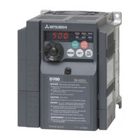
Mitsubishi Electric FR-D740-0.75K Instruction Manual (313 pages)
Brand: Mitsubishi Electric
|
Category: Inverter
|
Size: 15.06 MB
Table of Contents
Advertisement
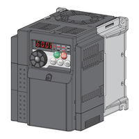
Mitsubishi Electric FR-D740-0.75K Instruction Manual (313 pages)
Brand: Mitsubishi Electric
|
Category: Inverter
|
Size: 15.22 MB
Table of Contents
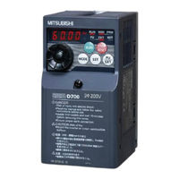
Mitsubishi Electric FR-D740-0.75K Instruction Manual (60 pages)
Brand: Mitsubishi Electric
|
Category: Inverter
|
Size: 4.54 MB
Table of Contents
Advertisement
Advertisement
Related Products
- Mitsubishi Electric FR-D740-0.4K
- Mitsubishi Electric FR-D740-012SC
- Mitsubishi Electric FR-D740-022-EC
- Mitsubishi Electric FR-D740-036-EC
- Mitsubishi Electric FR-D740-080-EC
- Mitsubishi Electric FR-D740-036
- Mitsubishi Electric FR-D740-012SC-EC
- Mitsubishi Electric FR-D7400-0.75K
- Mitsubishi Electric FR-D740-080
- Mitsubishi Electric FR-D740-050