Sign In
Upload
Manuals
Brands
Panasonic Manuals
Intercom System
VL-PS241
Panasonic VL-PS241 Manuals
Manuals and User Guides for Panasonic VL-PS241. We have
3
Panasonic VL-PS241 manuals available for free PDF download: Service Manual, Quick Manual
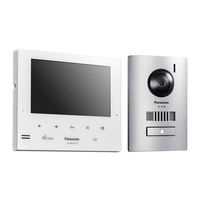
Panasonic VL-PS241 Service Manual (102 pages)
Video Intercom System
Brand:
Panasonic
| Category:
Intercom System
| Size: 7.07 MB
Table of Contents
Table of Contents
3
1 Safety Precautions
5
For Service Technicians
5
Insulation Resistance Test (by Insulation Resistance Tester)
5
Power Caution
5
2 Warning
6
Battery Caution
6
About Lead Free Solder (Pbf: Pb Free)
6
Suggested Pbf Solder
6
Discarding of P.C. Board
7
Note for Repairing
7
Disposal of Old Equipment
7
3 Specifications
8
Main Monitor Station (VL-MV75)
8
Door Phone (VL-V524)
8
Power Supply Unit (VL-PS241) (Indoor Use Only)
8
4 Technical Descriptions
9
Block Diagram
9
IC Operation
11
Monitor Station Section
11
Door Station Section
15
5 Location of Controls and Components
17
6 Installation Instructions
18
7 Operating Instructions
19
8 Service Mode
20
Things to Do after Replacing IC
20
Main Monitor Station
20
9 Troubleshooting Guide
21
Operation Check of the Door Station
21
Operation Check of the Main Monitor Station
25
Defect of the Communication between the Main Monitor Station and the Extension Monitor
26
Defect of the Extension Monitor Video Recording
27
Defect of the Main Monitor Station Power Supply
28
Defect of the Main Monitor Station Video Recording
33
Defect of the Communication between the Main Monitor Station and the Door Station
34
Defect of the Communication between the Extension Monitor Station and the Door Station
35
Defect of the Key Board Unit
36
Signal Route
37
10 Disassembly and Assembly Instructions
43
Main Monitor Station
43
How to Remove the DC Cable [No.1]
43
How to Remove the Cabinet Cover [No.2]
43
How to Remove the Main Board, Speaker and LCD [No.3]
44
How to Remove the Power Board, Key Board [No.4]
45
Door Station
46
How to Remove the Front Panel [No.1]
46
How to Remove the Door Station [No.2]
47
How to Remove the Main Board and Camera Unit [No.3]
48
How to Remove the MIC Board and Speaker [No.4]
49
Installation of the Lead Wires
51
Item to be Checked after Completion of Assembly (Camera Lens Angle Adjustment)
51
Power Supply Unit
52
11 Measurements and Adjustments
53
Main Monitor Station
53
Main Board
53
Factory Mode
55
Door Station
58
12 Miscellaneous
59
How to Replace the Flat Package IC
59
Preparation
59
Flat Package IC Removal Procedure
59
Flat Package IC Installation Procedure
60
Bridge Modification Procedure
60
13 Schematic Diagram
61
Main Monitor Station
62
Main Board (1) / External I/F
62
Main Board (2) / BBIC
63
Main Board (3) / DPJP3_KEY
64
Main Board (4) / LCD
65
Main Board (5) / External I/F_Electric Lock
66
Main Board (6) / DCDC
67
Main Board (7) / am Communication_Base Unit
68
Main Board (8) / am Communication_Add Base Unit
69
Main Board (9) / KEY
70
Power Board
71
Door Station
72
Main Board
72
MIC Board
73
Power Supply Unit
74
Power Board
74
14 Printed Circuit Board
75
Main Monitor Station
75
Main Board (Component View)
75
Main Board (Bottom View)
76
Key Board
77
Power Board
78
Door Station Board
79
Main Board
79
MIC Board
80
Power Supply Unit Board
81
Power Board (Component View)
81
Power Board (Bottom View)
82
15 Exploded View and Replacement Parts List
83
Exploded View
83
Main Monitor Station
83
Door Station
84
Power Supply Unit
85
Accessories and Packing Materials Location
86
Replacement Parts List
89
Main Monitor Station
89
Door Station
97
Power Supply Unit
99
Accessories and Packing Materials
100
Fixtures and Tools
101
Advertisement
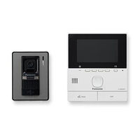
Panasonic VL-PS241 Service Manual (88 pages)
Video Intercom System
Brand:
Panasonic
| Category:
Intercom System
| Size: 3.67 MB
Table of Contents
Table of Contents
2
1 Safety Precautions
4
For Service Technicians
4
Power Caution
4
2 Warning
5
About Lead Free Solder (Pbf: Pb Free)
5
Suggested Pbf Solder
5
Insulation Resistance Test
6
Discarding of P.C. Board
6
Note for Repairing
6
3 Specifications
7
Main Monitor Station (VL-MVN511)
7
Power Supply Unit (VL-PS241) (Indoor Use Only)
7
Relay Box (VL-RLY1)
7
Door Station (VL-V522LCE)
8
4 Technical Descriptions
9
What Is a Video Intercom
9
Video Intercom
9
Block Diagram
9
Cmos Image Sensor Unit Block
10
DSP (Digital Signal Processor) Block
10
FM Modulation Block
10
FM Demodulation Block
10
LCD Controller and Color LCD Module
10
Voice
11
Call Signal
11
IC Operation
12
Monitor Station Section
12
Door Station Section
15
Relay Box Section
17
5 Location of Controls and Components
18
6 Installation Instructions
18
7 Operating Instructions
18
8 Troubleshooting Guide
19
Operation Check of the Door Station
19
Operation Check of the Main Monitor Station
22
Defect of the Main Monitor Station Power Supply
23
Defect of the Wifi Communication
26
Defect of the Main Monitor Station Video Recording
27
Defect of the Communication between the Main Monitor Station and the Door Station
28
Defect of the Communication between the Door Station and the PBX
29
Defect of the Operation of the Electric Lock
30
Defect of the External Input
30
Error Messages
31
Signal Route
32
9 Disassembly and Assembly Instructions
35
Main Monitor Station
35
How to Remove the DC Cable [No.1]
35
How to Remove the Cabinet Cover [No.2]
35
How to Remove the Main Board, MIC Board, Speaker and LCD [No.3]
36
Door Station
37
How to Remove the Mounting Base [No.1]
37
How to Remove the Main Board and Camera Unit [No.2]
38
How to Remove the MIC Board and Speaker [No.3]
39
How to Remove the Front Panel [No.4]
41
Installation of the Lead Wires
42
Assembly (Camera Lens Angle Adjustment)
42
Power Supply Unit
43
Relay Box
44
10 Measurements and Adjustments
45
Main Monitor Station
45
Connections
45
Things to Do after Replacing
46
When Replacing BBIC and X'tal
47
Factory Mode
48
11 Miscellaneous
52
How to Replace the Flat Package
52
Preparation
52
Flat Package IC Removal Procedure
52
Flat Package IC Installation Procedure
52
Bridge Modification Procedure
52
12 Schematic Diagram
53
Main Monitor Station
53
Main Board (1)
53
Main Board (2) / MIC Board
54
Main Board (3)
55
Main Board (4)
56
Power Board
57
Door Station
58
Main Board / MIC Board
58
Power Supply Unit
59
Power Board
59
Relay Box
60
Relay Board
60
13 Appendix Information of Schematic Diagram
61
14 Printed Circuit Board
62
Main Monitor Station
62
Main Board (Component View)
62
Main Board (Bottom View)
63
Power Board (Component View)
64
Power Board (Bottom View)
65
MIC Board
66
Door Station Board
67
Main Board
67
MIC Board
68
Power Supply Unit Board
69
Power Board (Component View)
69
Power Board (Bottom View)
70
Relay Box Board
71
Relay Board (Component View)
71
Relay Board (Bottom View)
72
15 Exploded View and Replacement Parts List
73
Exploded View
73
Main Monitor Station
73
Door Station
74
Power Supply Unit
75
Relay Box
76
Accessories and Packing Materials Location
77
Replacement Parts List
79
Main Monitor Station
79
Door Station
84
Power Supply Unit
86
Relay Box
87
Accessories and Packing Materials
87
Fixtures and Tools
87
Item to be Checked after Completion of 16 Change Information
88
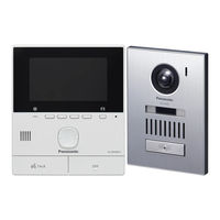
Panasonic VL-PS241 Quick Manual (2 pages)
Video Intercom System
Brand:
Panasonic
| Category:
Intercom System
| Size: 2.33 MB
Advertisement
Advertisement
Related Products
Panasonic VL-PS240
Panasonic VL-V700
Panasonic VL-SVD273
Panasonic VL-VN1700
Panasonic VL-SWD272
Panasonic VL-VM503
Panasonic VL-VM602EX
Panasonic VL-V524
Panasonic VL-SW251SX
Panasonic VL-SV75AZ
Panasonic Categories
Camcorder
Air Conditioner
TV
Digital Camera
Cordless Telephone
More Panasonic Manuals
Login
Sign In
OR
Sign in with Facebook
Sign in with Google
Upload manual
Upload from disk
Upload from URL