Sign In
Upload
Manuals
Brands
Philips Manuals
Flood Light
VARI-Lite VL4000
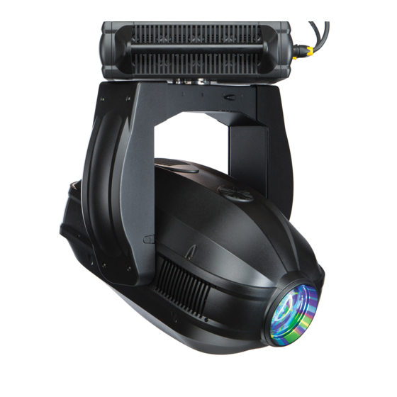
Philips VARI-Lite VL4000 Manuals
Manuals and User Guides for Philips VARI-Lite VL4000. We have
7
Philips VARI-Lite VL4000 manuals available for free PDF download: Service Manual, User Manual, Quick Start Manual
Philips VARI-Lite VL4000 Service Manual (330 pages)
Spot Luminaire
Brand:
Philips
| Category:
DJ Equipment
| Size: 28.6 MB
Table of Contents
Table of Contents
15
Introduction
21
About this Manual
21
Additional Documentation
21
Customer Service
22
Technical Bulletins and Notices
22
Chapter 1. Description
23
Features
24
Product Features
24
Technical Specifications
25
Components
26
External Luminaire Components
26
Head and Yoke Components
27
Enclosure Components
28
Chapter 2. Maintenance & Service
29
Troubleshooting
30
Error Messages
30
Troubleshooting Guide
31
Routine Maintenance Procedures Lamp Removal and Installation
33
Fixed Color Wheel Filter Removal and Installation
36
Rotating Gobo Removal and Installation
39
Animation Wheels Removal and Installation
42
Cleaning Optical Lenses and Filters
44
Service Procedures
45
Upper Enclosure Covers Removal
45
PFC Insulating Duct
46
Lamp Driver Insulation Duct Removal
47
Lamp Driver Insulation Duct Air Seal Replacement
48
Main Control Board (MCB)
49
Lamp Driver
51
Pan Encoder PCB
52
Pan Motor Assembly
53
Pfc
55
Pan Driver Board
56
Low Voltage Supply (LVS)
57
Upper Enclosure Fan
58
Neutrik True One AC Input Connector
59
DMX PCB Assembly
60
Display Overlay
61
USB Port
62
Upper Enclosure Air Filters (to Clean or Replace)
63
Pan Belt
64
Yoke Arm Covers Removal
66
Yoke Base Cover
67
Igniter Assembly
68
Tilt Lock Arm Assembly
69
Tilt Driver
70
Tilt Encoder
71
Tilt Motor Assembly
72
Tilt Belt
74
Yoke Assembly
76
Luminaire Head Covers Removal
79
Front Side Rail Covers
80
Input Air Filter
80
Rear Side Rail Cover Removal
81
Rear Cover Removal
82
Color Assembly Removal
83
Gobo / Shutter / Animation Assembly Removal
84
Optics Assembly Removal
85
Inlet Fan
86
Power Distribution Board
87
Base Lamp Fan
88
Tip Lamp Fan
89
UV Glass Assembly
90
Bottom Exhaust Fin Assembly
91
Top Exhaust Fin Assembly
92
Reflector Assembly
93
Retro Reflector Assembly
94
Ellipsoidal Reflector
95
Lamp Socket
96
Optics Assembly Components
97
Driver Board E
97
Driver Board F
99
Frost Divergence Sensor
100
Prism Divergence Sensor
101
Zoom or Compensation Sensor
102
Prism Arm Sensor
103
Frost Arm Sensor
104
Frost Motor or Motor Stabilizer
105
Frost Divergence Motor
106
Prism Index Sensor
107
Prism Rotate Motor
108
Prism Arm Motor & Stabilizer
109
Prism Divergence Motor
110
Compensation Motor
111
Zoom Motor & Stabilizer
112
Zoom Belt
113
Gobo/Shutter/Animation Assembly Components
114
Driver Board C
114
Driver Board D
116
Shutter Driver Board (9 Way)
118
Iris Motor
120
Iris Cable
121
Animation Wheel 1 & 2 Assembly
122
Animation Wheel Arm Sensor
123
Animation Index Belt
124
Animation Index Motor & Arm Belt
125
Animation Index Sensors
127
Gobo Wheel 1 Rotate Belt
128
Gobo Wheel 1 Index Belt
129
Gobo Wheel 2 Index Belt & Rotate Belt
130
Gobo Wheel 2 Index Sensor
132
Edge Motor Brackets and Support Brace Removal
133
Gobo Wheel 1 Index Motor
134
Gobo Wheel 1 Rotate Motor
135
Gobo Wheel 2 Rotate Motor
136
Gobo Wheel 2 Index Motor
137
Gobo Wheel 1 Index Sensor and Wheel 1 Rotate Sensor
138
Gobo Wheel 2 Rotate Sensor
139
Animation Arm Motors 1 or 2
140
Shutter Assembly & Belt
141
Shutter Sensor
142
Shutter Blade Motor
143
Shutter Rotate Motor
144
Iris Assembly
145
Color Assembly Components
146
Driver Board B
146
Driver Board a
148
Color Wheel 2 Sensor
150
Fixed Color Wheel Assembly & Color Wheel 1 Sensor
151
Fixed Color Wheel 1 & 2 Motors
152
Fixed Color Wheel 2 & Belt
153
Fixed Color Wheel 1 & Belt
154
CTO Filters
155
Yellow Filters
156
Cyan Filters
157
Magenta Filters
158
CYM Color Sensor
159
Color Filter Belt Assembly
160
Color Motor Assembly
161
Strobe Assembly
162
Strobe Blades
163
Strobe Motor
165
Dimmer Flags
166
Dimmer Belt
167
Dimmer Motor
168
Dimmer Sensor
169
Chapter 3. Illustrated Parts Breakdown
171
Drawing Trees
172
VL4000 Spot Luminaire (Part 1)
172
VL4000 Spot Luminaire (Part 2)
173
VL4000 Spot Luminaire (Part 3)
174
VL4000 Spot Luminaire (Part 4)
175
VL4000 Spot Luminaire (Part 5)
176
VL4000 Spot Luminaire (Part 6)
177
Principle of Operation
178
VL4000 Spot Functional Block Diagram
178
Top Assembly
179
Included Items Kit, VL4000 Spot
179
VL4000 Spot Luminaire
181
VL4000 Generic Luminaire Assembly
183
VL4000 Head Cover Assembly
185
VL4000 Yoke Arm Cover Assembly
186
Stabilizer Assembly
187
Head Assembly
189
Head Frame Assembly
189
VL4000 Zoom Spot Assembly
191
Prism Motor Assembly
195
Prism Assembly
197
Frost Motor Assembly
199
Frost Flag Assembly
201
Lens Group 3 Motor Assembly
202
Slotted Optical Switch
204
Back End Assembly
205
Reflector Assembly
207
Lamp Cover Assembly
208
5Mm Motor Shaft Damper Assembly
209
Shutter/Gobo/Animation Module Assembly
211
Gobo Wheel 1 Assembly
217
Gobo Wheel 2 Assembly
219
Gobo 1 Sensor Index Assembly
221
Gobo 2 Sensor Index Assembly
222
Edge Motor Assembly
223
Gobo Bulkhead Left Bracket Assembly
224
Gobo Bulkhead Right Bracket Assembly
225
Animation Wheel 1 Assembly
226
Animation Wheel 1 Motor Assembly
228
Animation Wheel 2 Assembly
229
Animation Wheel 2 Motor Assembly
231
Shutter Bulkhead with Rotation Assembly
232
Shutter Module Assembly
234
Shutter Rotate Motor Assembly
238
Shutter Rotate Adjustable Roller Arm Assembly
239
Color Module Assembly
241
210 Groove Belt Assembly
246
Groove Belt Assembly
247
Fixed Color Wheel Assembly
248
Fixed Color Wheel 1 Assembly
250
Fixed Color Wheel 2 Assembly
252
Fixed Color Motor Assembly
254
Cross-Flow Blower Assembly
255
Left Strobe Assembly
256
Right Strobe Assembly
258
Control Belt Idler Assembly
260
Color Flags Sensor Board Assembly
261
Yoke Assembly Yoke Assembly
263
Tilt Motor Assembly
265
Tilt Motor with Pulley Assembly
267
Enclosure Assembly Upper Enclosure Assembly
269
Upper Enclosure Assembly - Part 1
270
Upper Enclosure Assembly - Part 2
272
Upper Enclosure Assembly - Part 3
274
Upper Enclosure Assembly - Part 4
276
Side Mount Fan Assembly
278
Front Panel Assembly
279
Side Mount Filter Holder Assembly
281
Pan Bearing / Pulley Assembly
282
Pan / Fan Driver Board Assembly
284
Pan Module Assembly
285
Upper Enclosure Cover Assembly
287
Cable Assemblies
289
LVS Chassis Ground Cable Assembly
289
VL4000 Pan / Tilt Cable Assembly
290
VL4000 Tilt Cable Assembly
291
VL4000 Color Power Distribution Cable Assembly
292
VL4000 Main from MCB Data Cable Assembly
293
VL4000 Main to Bulkheads Data Cable Assembly
294
VL4000 Lamp Base & Tip Fan Extension Cable Assembly
295
VL4000 Main Power Distribution Cable Assembly
296
VL4000 Lamp Socket Cable Assembly
297
VL4000 Gobo Bulkhead 1 Cable Assembly
298
VL4000 Gobo Bulkhead 2 Cable Assembly
299
VL4000 Gobo Bulkhead 3 Cable Assembly
300
VL4000 Data Network Extension Cable Assembly
301
VL4000 Shutter 1 Cable Assembly
302
VL4000 Shutter 2 Cable Assembly
303
VL4000 Shutter 3 Cable Assembly
304
VL4000 Power Distribution Output-Shutter Cable Assembly
305
VL4000 Data Network Cable Assembly
306
VL4000 Color Bulkhead 1 Cable Assembly
307
VL4000 Color Bulkhead 2 Cable Assembly
308
VL4000 Color Bulkhead 3 Cable Assembly
309
VL4000 Color Bulkhead 4 Cable Assembly
310
VL4000 Color a to Color B Cable Assembly
311
VL4000 Ballast to Ignitor Cable Assembly
312
VL4000 Pan / Power Distribution Input Cable Assembly
313
VL4000 Enclosure PFC Input Cable Assembly
314
VL4000 Enclosure PFC Output Cable Assembly
315
VL4000 DMX Cable Assembly
316
VL4000 Ballast Control Cable Assembly
317
VL4000 USB Interface Cable Assembly
318
VL4000 Thermal Control Cable Assembly
319
VL4000 Chassis to Yoke Cable Assembly
320
VL4000 AC Input Connector Assembly
321
VL4000 Optics-E to Optics-F Data Cable Assembly
322
VL4000 Optics Bulkhead 3 Cable Assembly
323
VL4000 Optics Bulkhead 4 Cable Assembly
324
VL4000 Optics Bulkhead 1 Cable Assembly
325
VL4000 Optics Bulkhead 2 Cable Assembly
326
Advertisement
Philips VARI-Lite VL4000 Service Manual (320 pages)
BeamWash Luminaire
Brand:
Philips
| Category:
Light Fixture
| Size: 28.89 MB
Table of Contents
Table of Contents
15
Introduction
21
About this Manual
21
Additional Documentation
21
Customer Service
22
Technical Bulletins and Notices
22
Chapter 1. Description
23
Features
24
Product Features
24
Technical Specifications
25
Components
26
External Luminaire Components
26
Head and Yoke Components
27
Enclosure Components
28
Chapter 2. Maintenance & Service
29
Troubleshooting
30
Error Messages
30
Troubleshooting Guide
31
Routine Maintenance Procedures
32
Lamp Removal and Installation
32
Fixed Color Wheel Filter Removal and Installation
34
Rotating Gobo Removal and Installation
36
Animation Wheel Removal and Installation
39
Prism Removal and Installation
41
Cleaning Optical Lenses and Filters
43
Service Procedures
44
Upper Enclosure Covers Removal
44
PFC Insulating Duct
45
Lamp Driver Insulation Duct Removal
46
Lamp Driver Insulation Duct Air Seal Replacement
47
Main Control Board (MCB)
48
Lamp Driver
50
Pan Encoder PCB
51
Pan Motor Assembly
52
Pfc
54
Pan Driver Board
55
Low Voltage Supply (LVS)
56
Upper Enclosure Fan
57
Neutrik True One AC Input Connector
58
DMX PCB Assembly
59
Display Overlay
60
USB Port
61
Upper Enclosure Air Filters (to Clean or Replace)
62
Pan Belt
63
Yoke Arm Covers Removal
65
Yoke Base Cover
66
Igniter Assembly
67
Tilt Lock Arm Assembly
68
Tilt Driver
69
Tilt Encoder
70
Tilt Motor Assembly
71
Tilt Belt
73
Yoke Assembly
75
Luminaire Head Covers Removal
78
Front Side Rail Covers
79
Input Air Filter
79
Rear Side Rail Cover Removal
80
Rear Cover Removal
81
Gobo / Animation Assembly
82
Color Assembly
83
Nose Cover
84
Optics Assembly
85
Inlet Fan
86
Power Distribution Board
87
Base Lamp Fan
88
Tip Lamp Fan
89
UV Glass Assembly
90
Bottom Exhaust Fin Assembly
91
Top Exhaust Fin Assembly
92
Reflector Assembly
93
Retro Reflector
94
Ellipsoidal Reflector
95
Lamp Socket
96
Optics Components
97
Driver Board G (7 Way Board)
97
Edge & Zoom Sensor
99
Lenticular Lens Assembly
100
Lenticular Lens Sensor
101
Lenticular Rotate Sensor
102
Lenticular Lens Belt
103
Lenticular Arm Motor
104
Lenticular Arm Belt
105
Lenticular Rotate Motor
106
Prism Assembly
107
Prism Arm Sensor
108
Prism Rotate Sensor
109
Prism Arm Motor
110
Prism Arm Belt
111
Prism Rotate Belt
112
Prism Rotate Motor
113
Prism Glass Change
114
Wash Lens Sensor
115
Wash Lens Motor
116
Wash Lens Belt or Wash Lens
117
Zoom Belt
118
Zoom Stabilizer
119
Zoom Motor
120
Edge Belt
121
Edge Stabilizer
122
Edge Motor
123
Gobo Assembly
124
Driver Board C
124
Driver Board D
126
Iris Assembly
128
Iris Motor
129
Iris Cable
130
Iris Assembly
132
Animation Assembly
133
Animation Wheel Arm Sensor
134
Animation Index Belt & Animation Wheel Removal
135
Animation Index Motor & Arm Belt
136
Animation Index Sensor
138
Gobo Wheel 1 Rotate Belt
139
Gobo Wheel 1 Index Belt
140
Gobo Wheel 2 Index Belt & Rotate Belt
141
Gobo Wheel 2 Index Sensor
143
Gobo Wheel 1 Index Motor
144
Gobo Wheel 1 Rotate Motor
145
Gobo Wheel 2 Rotate Motor
146
Gobo Wheel 2 Index Motor
147
Gobo Wheel 1 Index Sensor & Wheel 1 Rotate Sensor
148
Gobo Wheel 2 Rotate Sensor
149
Animation Arm Motor & Motor Stabilizer
150
Color Assembly Components
151
Driver Board B
151
Driver Board a
153
Color Wheel 2 Sensor
155
Fixed Color Wheel 1 Assembly & Color Wheel 1 Sensor
156
Fixed Color Wheel 1 & 2 Motor
157
Fixed Color Wheel 2 & Belt
158
Fixed Color Wheel 1 & Belt
159
CTO Filters
160
Yellow Filters
161
Cyan Filters
162
Magenta Filters
163
CYM Color Sensor
164
Color Belt Assembly
165
Color Motor Assembly
166
Strobe Assembly
167
Strobe Blades
168
Strobe Motor
170
Dimmer Flags
171
Dimmer Belt
172
Dimmer Motor
173
Dimmer Sensor
174
Chapter 3. Illustrated Parts Breakdown
175
Drawing Trees
176
VL4000 Beamwash Luminaire (Part 1)
176
VL4000 Beamwash Luminaire (Part 2)
177
VL4000 Beamwash Luminaire (Part 3)
178
VL4000 Beamwash Luminaire (Part 4)
179
VL4000 Beamwash Luminaire (Part 5)
180
VL4000 Beamwash Luminaire (Part 6)
181
Principle of Operation
182
VL4000 Beamwash Functional Block Diagram
182
Top Assembly
183
Included Items Kit, VL4000 Beamwash
183
VL4000 Beamwash Luminaire
185
VL4000 Beamwash Generic Luminaire Assembly
187
VL4000 Beamwash Head Cover Assembly
190
VL4000 Beamwash Yoke Arm Cover Assembly
191
Stabilizer Assembly
192
Back Cover Assembly
193
Head Assembly Head Frame Assembly
195
VL4000 Beamwash Optics Assembly
197
Edge Lens Motor Assembly
201
5Mm Motor Shaft Damper Assembly
202
Zoom Lens Motor Assembly
203
Lenticular with Motors Assembly
204
Lenticular Arm Assembly
206
Prism Assembly
208
Prism Arm Assembly
210
Wash Assembly
211
Wash Arm Motor Assembly
212
Slotted Optical Switch
213
Back End Assembly
214
Reflector Assembly
216
Lamp Cover Assembly
217
Gobo/Animation Module Assembly
219
Gobo Wheel 1 Assembly
225
Gobo Wheel 2 Assembly
227
Gobo 1 Sensor Index Assembly
229
Gobo 2 Sensor Index Assembly
230
Concurrent Animation Wheel Assembly
231
Animation Wheel 2 Motor Assembly
233
Front Gobo Bulkhead with Iris Assembly
234
Iris Module Assembly
236
Color Module Assembly
239
210 Groove Belt Assembly
244
Groove Belt Assembly
245
Fixed Color Wheel Assembly
246
Fixed Color Wheel 1 Assembly
248
Fixed Color Wheel 2 Assembly
250
Fixed Color Motor Assembly
252
Cross-Flow Blower Assembly
253
Left Strobe Assembly
254
Right Strobe Assembly
256
Control Belt Idler Assembly
258
Color Flags Sensor Board Assembly
259
Yoke Assembly Yoke Assembly
261
Double Rollers Tilt Motor Assembly
263
Tilt Motor with Pulley Assembly
265
Tilt Belt Tension Rollers Assembly
266
Enclosure Assembly Upper Enclosure Assembly
267
Upper Enclosure Assembly - Part 1
268
Upper Enclosure Assembly - Part 2
270
Upper Enclosure Assembly - Part 3
272
Upper Enclosure Assembly - Part 4
274
Side Mount Fan Assembly
276
Front Panel Assembly
277
Side Mount Filter Holder Assembly
279
Pan Bearing / Pulley Assembly
280
Pan / Fan Driver Board Assembly
282
Pan Module Assembly
283
Upper Enclosure Cover Assembly
285
Cable Assemblies
287
LVS Chassis Ground Cable Assembly
287
VL4000 Pan / Tilt Cable Assembly
288
VL4000 Color Power Distribution Cable Assembly
289
VL4000 Lamp Base & Tip Fan Extension Cable Assembly
290
VL4000 Data Network Extension Cable Assembly
291
VL4000 Color Bulkhead 1 Cable Assembly
292
VL4000 Color Bulkhead 2 Cable Assembly
293
VL4000 Color Bulkhead 3 Cable Assembly
294
VL4000 Color Bulkhead 4 Cable Assembly
295
VL4000 Color a to Color B Cable Assembly
296
VL4000 Pan / Power Distribution Input Cable Assembly
297
VL4000 Enclosure PFC Input Cable Assembly
298
VL4000 Enclosure PFC Output Cable Assembly
299
VL4000 DMX Cable Assembly
300
VL4000 Ballast Control Cable Assembly
301
VL4000 USB Interface Cable Assembly
302
VL4000 Thermal Control Cable Assembly
303
VL4000 Chassis to Yoke Cable Assembly
304
VL4000 AC Input Connector Assembly
305
VL4000 Tilt with Shield Cable Assembly
306
VL4000 Beamwash Power Dist Cable Assembly
307
VL4000 Main from MCB Data Cable Assembly
308
VL4000 Main to Bulkheads Data Cable Assembly
309
VL4000 Beamwash Inlet Fan Extension Cable Assembly
310
VL4000 Ballast to Ignitor Cable Assembly
311
VL4000 Beamwash Gobo Bulkhead 1 Cable Assembly
312
VL4000 Beamwash Gobo Bulkhead 2 Cable Assembly
313
VL4000 Beamwash Optics Bulkhead Cable Assembly
314
VL4000 Beamwash Lamp Socket Cable Assembly
315
Philips VARI-Lite VL4000 Service Manual (200 pages)
Spot Luminaire
Brand:
Philips
| Category:
DJ Equipment
| Size: 14.45 MB
Table of Contents
Table of Contents
15
Introduction
19
About this Manual
19
Additional Documentation
19
Customer Service
20
Technical Bulletins and Notices
20
Chapter 1. Description
21
Features
22
Product Features
22
Features Product Features
22
Technical Specifications
23
Components
24
External Luminaire Components
24
Components External Luminaire Components
24
Head and Yoke Components
25
Enclosure Components
26
Chapter 2. Rountine Maintenance
27
Troubleshooting
28
Error Messages
28
Troubleshooting Error Messages
28
Troubleshooting Guide
29
Routine Maintenance Procedures Lamp Removal and Installation
31
Fixed Color Wheel Filter Removal and Installation
34
Rotating Gobo Removal and Installation
36
Animation Wheels Removal and Installation
39
Cleaning Optical Lenses and Filters
41
Chapter 3. Illustrated Parts Breakdown
43
Drawing Trees
44
VL4000 Spot Luminaire (Part 1)
44
VL4000 Spot Luminaire (Part 2)
45
VL4000 Spot Luminaire (Part 3)
46
VL4000 Spot Luminaire (Part 4)
47
VL4000 Spot Luminaire (Part 5)
48
VL4000 Spot Luminaire (Part 6)
49
Principle of Operation
50
VL4000 Spot Functional Block Diagram
50
Top Assembly
51
Included Items Kit, VL4000 Spot
51
VL4000 Spot Luminaire
53
VL4000 Generic Luminaire Assembly
55
VL4000 Head Cover Assembly
57
VL4000 Yoke Arm Cover Assembly
58
Stabilizer Assembly
59
Head Assembly
61
Head Frame Assembly
61
VL4000 Zoom Spot Assembly
63
Prism Motor Assembly
67
Prism Assembly
69
Frost Motor Assembly
71
Frost Flag Assembly
73
Lens Group 3 Motor Assembly
74
Slotted Optical Switch
76
Back End Assembly
77
Reflector Assembly
79
Lamp Cover Assembly
80
Shutter/Gobo/Animation Module Assembly
81
Gobo Wheel 1 Assembly
87
Gobo Wheel 2 Assembly
89
Gobo 1 Sensor Index Assembly
91
Gobo 2 Sensor Index Assembly
92
Edge Motor Assembly
93
Gobo Bulkhead Left Bracket Assembly
94
Gobo Bulkhead Right Bracket Assembly
95
Animation Wheel 1 Assembly
96
Animation Wheel 1 Motor Assembly
98
Animation Wheel 2 Assembly
99
Animation Wheel 2 Motor Assembly
101
Shutter Bulkhead with Rotation Assembly
102
Shutter Module Assembly
104
Shutter Rotate Motor Assembly
108
Shutter Rotate Adjustable Roller Arm Assembly
109
Color Module Assembly
111
210 Groove Belt Assembly
116
Groove Belt Assembly
117
Fixed Color Wheel Assembly
118
Fixed Color Wheel 1 Assembly
120
Fixed Color Wheel 2 Assembly
122
Fixed Color Motor Assembly
124
Cross-Flow Blower Assembly
125
Left Strobe Assembly
126
Right Strobe Assembly
128
Control Belt Idler Assembly
130
Color Flags Sensor Board Assembly
131
Yoke Assembly Yoke Assembly
133
Tilt Motor Assembly
135
Tilt Motor with Pulley Assembly
137
Enclosure Assembly
139
Upper Enclosure Assembly
139
Upper Enclosure Assembly - Part 1
140
Upper Enclosure Assembly - Part 2
142
Upper Enclosure Assembly - Part 3
144
Upper Enclosure Assembly - Part 4
146
Side Mount Fan Assembly
148
Front Panel Assembly
149
Side Mount Filter Holder Assembly
151
Pan Bearing / Pulley Assembly
152
Pan / Fan Driver Board Assembly
154
Pan Module Assembly
155
Upper Enclosure Cover Assembly
157
Section Is for Reference Only
159
Cable Assemblies
159
LVS Chassis Ground Cable Assembly
159
VL4000 Pan / Tilt Cable Assembly
160
VL4000 Tilt Cable Assembly
161
VL4000 Color Power Distribution Cable Assembly
162
VL4000 Main from MCB Data Cable Assembly
163
VL4000 Main to Bulkheads Data Cable Assembly
164
VL4000 Lamp Base & Tip Fan Extension Cable Assembly
165
VL4000 Main Power Distribution Cable Assembly
166
VL4000 Lamp Socket Cable Assembly
167
VL4000 Gobo Bulkhead 1 Cable Assembly
168
VL4000 Gobo Bulkhead 2 Cable Assembly
169
VL4000 Gobo Bulkhead 3 Cable Assembly
170
VL4000 Data Network Extension Cable Assembly
171
VL4000 Shutter 1 Cable Assembly
172
VL4000 Shutter 2 Cable Assembly
173
VL4000 Shutter 3 Cable Assembly
174
VL4000 Power Distribution Output-Shutter Cable Assembly
175
VL4000 Data Network Cable Assembly
176
VL4000 Color Bulkhead 1 Cable Assembly
177
VL4000 Color Bulkhead 2 Cable Assembly
178
VL4000 Color Bulkhead 3 Cable Assembly
179
VL4000 Color Bulkhead 4 Cable Assembly
180
VL4000 Color a to Color B Cable Assembly
181
VL4000 Ballast to Ignitor Cable Assembly
182
VL4000 Pan / Power Distribution Input Cable Assembly
183
VL4000 Enclosure PFC Input Cable Assembly
184
VL4000 Enclosure PFC Output Cable Assembly
185
VL4000 DMX Cable Assembly
186
VL4000 Ballast Control Cable Assembly
187
Vari Lite - Vl4000 Spot Luminaire Service Anual
188
VL4000 USB Interface Cable Assembly
188
VL4000 Thermal Control Cable Assembly
189
VL4000 Chassis to Yoke Cable Assembly
190
VL4000 AC Input Connector Assembly
191
VL4000 Optics-E to Optics-F Data Cable Assembly
192
VL4000 Optics Bulkhead 3 Cable Assembly
193
VL4000 Optics Bulkhead 4 Cable Assembly
194
VL4000 Optics Bulkhead 1 Cable Assembly
195
VL4000 Optics Bulkhead 2 Cable Assembly
196
Advertisement
Philips VARI-Lite VL4000 User Manual (118 pages)
Spot Luminaire
Brand:
Philips
| Category:
Lighting Equipment
| Size: 5.83 MB
Table of Contents
Safety Notice
5
Table of Contents
15
Introduction
19
About this Manual
19
Additional Documentation
20
Text Conventions
20
Customer Service
21
Chapter 1. Description
23
Features
24
Overview
24
Features Overview
24
Components
26
Included Items
26
Replacement Items/Accessories
26
Components Included Items
26
Luminaire Components
27
Major Components
27
Chapter 2. Installation
29
Power and Data Cabling Requirements
30
Power
30
Current Vs. Voltage
32
Data Cables
33
Recommended Cable Types/Manufacturers
34
Termination Connector
34
Installation Procedures
35
Installing Lamp
35
Cautions & Warnings
35
Align Lamp for Maximum Beam Irradiance
37
Hanging the Luminaire
38
Floor Mounting the Luminaire
42
Connecting Data and Power
42
Powering up
43
Power-Up Procedure
43
Addressing
44
Program Starting Address
44
Program Starting Address Without Calibrating Luminaire
44
Addressing Program Starting Address
44
Transporting
45
Overview
45
Transportation and Shipping Case Requirements
45
Transporting Overview
45
Chapter 3. Operation
47
Color Control & Gobos
48
Color Mixing
48
Fixed Color Wheel 1
48
Fixed Color Wheel 2
49
Gobos
49
Rotating Gobo Wheel 1
50
Rotating Gobo Wheel 2
51
Animation Wheels
52
Animation Wheel 1 - Dichro*Fusion
52
Animation Wheel 2 - Wicked Waves
52
DMX Operation
53
VL4000 Spot Channel Mapping
53
Enhanced 16-Bit Channel Mapping (Default)
53
16-Bit Channel Mapping
58
Fixture Shutdown
62
Luminaire Timing
63
Luminaire Timing Channel Information
63
RDM Parameter Ids
71
VL4000 Spot Luminaire RDM Parameter Ids
71
Updating Software
74
PEGASUS Software
74
Application
74
Computer Requirements
74
Installing PEGASUS Software
74
Troubleshooting
75
Upload Cable LED Status Messages
75
Upload Cable Warning (Error) Message
76
Installing or Updating Luminaire Firmware
76
USB Upload Via USB Port
76
Using PEGASUS Uploader
76
Important Notes & Warnings
77
Transferring Software from Luminaire to Luminaire
78
Chapter 4. Menu System
81
Menu Operation
82
LCD Display and Menu System
82
Menu Controls
82
DMX Address
83
LCD Display and Menu System Operation
83
Operational Modes - Standard and Studio
83
Other LCD Display Features
84
LCD Menu Battery Operation
84
LCD Menu Proximity Sensor
84
Status Bar
84
Menu Tree
85
Menu System Functions
87
Self Tests
92
Running Parameter Tests
92
Diagnostic Tests
93
Test Descriptions
93
Service Menu Items
94
Set Tilt Cal
94
Gobo Offset
95
USB Logging
95
Appendix A. Maintenance
97
Equipment Handling
98
Locations/Use
98
Lamps
98
Heat
98
Lamp Life
98
Servicing
98
Electrostatic Discharge (ESD)
99
Printed Circuit Boards (Pcbs)
99
Solid State Electronics
99
Troubleshooting
100
Error Messages
100
Troubleshooting Error Messages
100
Troubleshooting Guide
101
Routine Maintenance
102
Cautions & Warnings
102
Lamp Removal and Installation
102
Routine Maintenance Lamp Removal and Installation
102
Fixed Color Wheel Filter Removal and Installation
104
Rotating Gobo Removal and Installation
106
Animation Wheels Removal and Installation
109
Cleaning Optical Lenses and Filters
111
Philips VARI-Lite VL4000 User Manual (110 pages)
Spot Luminaire
Brand:
Philips
| Category:
Flood Light
| Size: 7.15 MB
Table of Contents
Safety Notice
5
Table of Contents
15
Introduction
19
About this Manual
19
Additional Documentation
20
Text Conventions
20
Customer Service
21
Chapter 1. Description
23
Features
24
Overview
24
Features Overview
24
Components
26
Included Items
26
Replacement Items/Accessories
26
Components Included Items
26
Luminaire Components
27
Major Components
27
Chapter 2. Installation
29
Power and Data Cabling Requirements
30
Power
30
Current Vs. Voltage
32
Data Cables
33
Recommended Cable Types/Manufacturers
34
Termination Connector
34
Installation Procedures
35
Installing Lamp
35
Cautions & Warnings
35
Align Lamp for Maximum Beam Irradiance
37
Hanging the Luminaire
38
Floor Mounting the Luminaire
41
Connecting Data and Power
41
Powering up
42
Power-Up Procedure
42
Addressing
43
Program Starting Address
43
Program Starting Address Without Calibrating Luminaire
43
Addressing Program Starting Address
43
Transporting
44
Overview
44
Transportation and Shipping Case Requirements
44
Transporting Overview
44
Chapter 3. Operation
45
Color Control & Gobos
46
Color Mixing
46
Fixed Color Wheel 1
46
Fixed Color Wheel 2
47
Gobos
47
Rotating Gobo Wheel 1
48
Rotating Gobo Wheel 2
49
Animation Wheels
50
Animation Wheel 1 - Dichro*Fusion
50
Animation Wheel 2 - Wicked Waves
50
DMX Operation
51
VL4000 Spot Channel Mapping
51
Enhanced 16-Bit Channel Mapping (Default)
51
16-Bit Channel Mapping
56
Luminaire Timing
61
Luminaire Timing Channel Information
61
Updating Software
69
PEGASUS Software
69
Application
69
Computer Requirements
69
Installing PEGASUS Software
69
Troubleshooting
70
Upload Cable LED Status Messages
70
Upload Cable Warning (Error) Message
71
Installing or Updating Luminaire Firmware
71
Important Notes & Warnings
71
Updating VARI❋LITE Luminaires
71
Transferring Software from Luminaire to Luminaire
73
Chapter 4. Menu System
75
Menu Operation
76
LCD Display and Menu System
76
Menu Controls
76
DMX Address
77
LCD Display and Menu System Operation
77
Operational Modes - Standard and Studio
77
Other LCD Display Features
78
LCD Menu Battery Operation
78
LCD Menu Proximity Sensor
78
Status Bar
78
Menu Tree
79
Menu System Functions
81
Self Tests
85
Running Parameter Tests
85
Diagnostic Tests
86
Test Descriptions
86
Appendix A. Maintenance
89
Equipment Handling
90
Locations/Use
90
Lamps
90
Heat
90
Lamp Life
90
Servicing
90
Electrostatic Discharge (ESD)
91
Printed Circuit Boards (Pcbs)
91
Solid State Electronics
91
Troubleshooting
92
Error Messages
92
Troubleshooting Error Messages
92
Troubleshooting Guide
93
Routine Maintenance
94
Cautions & Warnings
94
Lamp Removal and Installation
94
Routine Maintenance Lamp Removal and Installation
94
Fixed Color Wheel Filter Removal and Installation
96
Rotating Gobo Removal and Installation
98
Animation Wheels Removal and Installation
101
Cleaning Optical Lenses and Filters
103
Philips VARI-Lite VL4000 Quick Start Manual (17 pages)
Vari-Lite BeamWash Luminaire
Brand:
Philips
| Category:
Lantern
| Size: 1.28 MB
Table of Contents
About this Guide
2
Additional Documentation
2
Customer Service
2
Safety Notice
3
Notes de Sécurité
4
Replacement Items/Accessories
6
Connecting Power and Data
7
Current Vs. Voltage
8
Connecting Data
8
Installation Procedures
9
Installing Lamp
9
Align Lamp for Maximum Beam Irradiance
11
Floor Mounting the Luminaire
11
Hanging the Luminaire
12
Menu Controls
14
LCD Display and Menu System Operation
14
DMX Address
14
Operational Modes - Standard and Studio
15
Status Bar
15
LCD Menu Proximity Sensor
15
Philips VARI-Lite VL4000 Quick Start Manual (17 pages)
Spot luminaire
Brand:
Philips
| Category:
Spotlight
| Size: 1.23 MB
Table of Contents
Additional Documentation
2
Customer Service
2
About this Guide
2
Safety Notice
3
Notes de Sécurité
4
Included Items
6
Replacement Items/Accessories
6
Connecting Power and Data
7
Current Vs. Voltage
8
Connecting Data
8
Installation Procedures
9
Installing Lamp
9
Align Lamp for Maximum Beam Irradiance
11
Floor Mounting the Luminaire
11
Hanging the Luminaire
12
Menu Operation
14
Menu Controls
14
Advertisement
Related Products
Philips VL500 Wash Luminaires
Philips Vari-Lite VL500
Philips Vari-Lite VL500D Wash
Philips Vari-Lite VL500 80V Wash
Philips Vari-Lite VL500A Wash
Philips VL440 Spot
Philips Vari-lite VL3015LT
Philips VL1000 TSD
Philips VL1000 AS
Philips Palette VL16
Philips Categories
TV
Monitor
Stereo System
Electric Shaver
CD Player
More Philips Manuals
Login
Sign In
OR
Sign in with Facebook
Sign in with Google
Upload manual
Upload from disk
Upload from URL