Sign In
Upload
Manuals
Brands
Siemens Manuals
Control Unit
AGM60.4A9
Siemens AGM60.4A9 Manuals
Manuals and User Guides for Siemens AGM60.4A9. We have
2
Siemens AGM60.4A9 manuals available for free PDF download: Basic Documentation, Manual
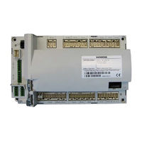
Siemens AGM60.4A9 Basic Documentation (248 pages)
Basic unit with integrated fuel-air ratio control for forced draft burners
Brand:
Siemens
| Category:
Control Unit
| Size: 5.11 MB
Table of Contents
Table of Contents
5
1 Safety Notes
12
Warning Notes
12
Mounting Notes
14
Lmv36
14
Agm60
15
Installation Notes
16
Use of the AGM60
17
Electrical Connections of LMV36
17
Lmv36
17
Agm60
18
Electrical Connection of Flame Detectors
18
Commissioning Notes
19
Notes on Settings and Parameter Settings
21
Standards and Certificates
22
Service Notes
22
Life Cycle
22
Disposal Notes
22
2 Makeup of Structure / Function Description
23
Lmv36
23
For North American
23
General Information
24
Agm60
25
Electrical Connections of Fuel Actuators
25
Continuous Operation
26
Fuel Changeover
26
Extra Fuel Selector
26
3 Type Summary
27
Lmv36
27
Agm60
27
Fuel Selector
27
4 Technical Data
28
Lmv36
28
Terminal Loading Inputs
28
Terminal Loading Outputs
29
Analog Output / Load Output X74 Pin 3
29
Cable Lengths
30
Cross-Sectional Areas
30
Connections of Actuators
30
Signal Cable AGV50
31
Environmental Conditions
31
Flame Detectors
32
Ionization Probe
32
UV Flame Detectors QRA2 / QRA4 / QRA10
34
Photoresistive Flame Detectors QRB
35
Switch Unit AGM60
36
Terminal Output Inputs
37
Terminal Output Outputs
37
Cable Lengths
38
Cross-Sectional Areas
38
Electrical Connections of Actuators
38
Environmental Conditions
38
5 Dimensions
39
Lmv36
39
Agm60
40
6 Display and Diagnostics
41
7 Basic Unit
42
Description of Inputs and Outputs
42
Flame Detectors
43
Loss of Flame
44
Extraneous Light
44
No Flame at the End of Safety Time (TSA)
45
Flame Intensity
45
Supervision of Flame Detector
45
Digital Inputs
46
Safety Loop X3-04 (Optional Pressure Switch-Max (Pmax)), Pin 1 and 2
46
(Burner Flange) X3-03, Pin 1 and 2
47
Input for External Controller (on / OFF) X5-03, Pin 1
47
Air Pressure Switch (APS) X3-02
48
Gas Pressure Switch for Gas Valve Proving (P LT) X9-04
49
Gas Pressure Switch-Min (Pmin), Start Release Gas X5-01
50
Oil Pressure Switch-Min (Pmin) X9-04 (X5-01 on AGM60
51
Setting the Time for Checking the Pressure Switch
52
Gas / Oil Pressure Switch-Max (Pmax) / or POC Contact, Start Release Oil X5-02
53
Fuel Selection
56
Reset X8-04, Pin 1
56
Digital Outputs
57
Output Alarm Type No-SI X3-05 Pin 2
57
Fan Motor Contactor Type si X3-05, Pin 1
57
Fan Continuous Purging X3-05, Pin 3
57
Output Ignition (Z) Type si (IGNITION) X4-02
58
Outputs Fuel Valves Type si (V1
59
Output Safety Valve (SV) Type si X6-03 / Magnetic Clutch
61
Output for Indication of Operation X8-04 Pin 2
61
Program Sequence
62
Time Parameters
62
Valve Proving
64
Valve Proving with Separate Pressure Switch (P LT) X9-04
65
Valve Proving Via Gas Pressure Switch-Min X5-01
66
Lockout Phase (Phase 00)
66
Safety Phase (Phase 02)
67
Special Functions During the Program Sequence
68
Reset / Manual Lockout
68
Alarm Upon Prevention of Startup
70
Possible Preventions of Startup
70
Repetition Counter
71
Start Without Prepurging (as Per en 676)
73
Gas Shortage Program
74
Program Stop Function
75
Forced Intermittent Operation (<24 Hours)
75
Low-Fire Shutdown
75
Continuous Fan
76
Test Function for Burner Approval - Loss-Of-Flame Test (TÜV Test)
77
Purging in the Lockout Position
78
Fuel Trains (Application Examples)
79
Sequence Diagrams
88
Gas Direct Ignition "G", "G Mod", "G Mod Pneu
89
Gas Pilot Ignition 1 "Gp1", "Gp1 Mod", "Gp1 Mod Pneu
90
Gas Pilot Ignition 2 "Gp2", "Gp2 Mod", "Gp2 Mod Pneu
91
Light Oil Direct Ignition "Lo", "Lo Mod", "Lo 2-Stage", "Lo 3-Stage
92
Light Oil Pilot Ignition "Lo Gp
93
Legend to Sequence Diagrams
94
Legend to the Sequence Diagrams
94
8 Agm60
97
System with AGM60
97
Connecting Cable between AGM60
98
9 Selection of Operating Mode
99
Deleting Curves
102
10 Connection to Load Controllers
103
Controller-On Contact X5-03 Pin 1
103
Load Controller Via BAC System X92
103
Manual Output
105
Output with Curve Settings
105
External Load Controller Via Analog Input X64 Pin 1 / X64 Pin 2
106
Thresholds for Modulating Operation
106
Switching Thresholds for Multistage Operation
107
Prioritization of Power Sources
108
Emergency Operation with Several Load Controllers
108
11 Electronic Fuel-Air Ratio Control
109
General
109
Behavior Outside the Operating Positions
109
Traveling Speed
109
Home Position
109
Prepurging
110
Ignition
110
Postpurging
110
Modulating Operation
111
Definition of Curves
111
Traveling Speed/Maximum Curve Slope
112
Entering the Running Position
113
Operating Position
113
Limitation of Modulation Range
114
Setting the Minimum and Maximum Output
115
Multistage Operation
116
Definition of Curves
116
Traveling Speed
116
Adjustment of Output
117
Entering the Operating Position
117
Operating Position
117
Limitation of Modulation Range
118
End of Operating Position
118
Notes on Settings and Parameter Settings
119
12 Actuators X53 / X54
120
Function Principle
120
Definition of Angles
120
Referencing
121
Reference Run
123
Direction of Rotation
125
Monitoring the Actuator Positions
126
Changing the Error Detection Band for Monitoring the Actuator Positions
128
Forced Travel
128
Detection of Line Interruptions
128
Protection against Mixup of Actuator
129
Proposal for Implementation
129
13 Fan Control
130
Function Principle
130
Activation of VSD/PWM Fan
130
VSD Control X74 Pin 3
131
PWM Fan Control X64 Pin 3
132
Safe Separation of Mains Voltage and Protective Extra Low-Voltage
132
Ramp Time
132
Acquisition of Speed
133
Acquisition of Speed with Proximity Switch
133
Acquisition of Speed with Hall Generator
134
Speed Control
135
Speed Supervision
136
Setting the Parameters of the VSD
137
Standardization of Speed
138
Control of Fan Motor with Pneumatic Fuel-Air Ratio Control
140
EMC of LMV36
141
Description of Connection Terminals
142
Vsd
142
PWM Fan
142
14 Load Output X74 Pin 3
143
Safe Separation of Mains Voltage and Extra Low-Voltage
143
Modulating Operation
143
2-Stage Operation
143
3-Stage Operation
144
15 Fuel Meter Input X75 Pin 1 / X75 Pin 2
145
Configuration of Fuel Meter
145
Types of Fuel Meters
145
Configuration of Pulses Per Volume Unit
145
Reading and Resetting the Meter Readings
145
Fuel Throughput
146
Configuration
146
Reading out the Fuel Throughput
146
16 Connection and Internal Diagram
147
17 Special Feature: Burner Identification (ID)
148
18 Connection to Superposed Systems
148
General Information and Building Automation Functions
148
Modbus
150
19 PC Software ACS410
151
20 Error History
152
Error Classes
152
Makeup of Error History
153
21 Lifecycle Function
154
22 Safety Notes on Use of the AZL2
154
23 Operating the AZL2
155
Description of Unit/Display and Buttons
155
Meaning of Symbols on the Display
156
Brightness of Display
156
Special Functions
157
Manual Lockout
157
Manual Control (Manual Request for Output)
157
Timeout for Menu Operation
158
Backup / Restore
159
Backup
160
Restore
162
24 Operation of Basic Unit Via the AZL2
164
Normal Display
164
Display in Standby Mode
164
Display During Startup / Shutdown
164
Display of Program Phases
164
Display of Program Phase with Remaining Running Time until End of the Phase Is Reached
164
List of Phase Displays
165
Display of Operating Position
166
Fault Status Messages, Display of Errors and Info
167
Display of Errors (Faults) with Lockout
167
Reset
167
Activating Info / Service Mode from Lockout
167
Error with Safety Shutdown
168
General Information
168
Prevention of Startup
168
Safety Loop
168
25 Menu-Driven Operation
169
Assignment of Levels
169
26 Info Level
170
Display of Info Level
172
Display of Info Values (Examples)
172
Identification Date
172
Identification Number
172
Burner Identification
173
Number of Startups Resettable
173
Total Number of Startups
174
End of Info Level
174
27 Service Level
175
Display of Service Level
175
Display of Service Values (Example)
176
Number of Faults
176
Error History
176
Intensity of Flame
176
End of Service Level
176
28 Parameter Level
177
Entry of Password
178
Entry of Burner Identification
180
Change of Heating Engineer's Password
181
Change of Oem's Password
182
Use of Parameter Level
182
Structure of Parameter Levels
183
Parameters Without Index, with Direct Display
184
Using the Example of Parameter 208: Program Stop
184
Parameters Without Index, with no Direct Display (with Parameters Having a Value Range >5 Digits)
186
Using the Example of Parameter 162: Operating Hours Resettable
186
Parameter with Index, with Direct Display
188
Using the Example of Parameter 501: No-Flame Positions Fuel Actuator
188
Parameters with Index, with no Direct Display
190
Using the Example of Parameter 701: Errors
190
Fuel-Air Ratio Curves - Settings and Commissioning
193
Initial Commissioning
193
Setting Curvepoints P0 and P9 for Modulating Operation ("G Mod", "Gp1 Mod", "Gp2 Mod" and "Lo Mod")
196
Setting Curvepoints P0 and P9 for "G Mod Pneu", "Gp1 Mod Pneu" and "Gp2 Mod Pneu
197
Warm Settings for Modulating Operation
198
Mod" and "Lo Mod")
198
Warm Settings for Modulating Mode ("G Mod Pneu", "Gp1 Mod Pneu" and "Gp2 Mod Pneu")
203
Cold Settings for "G Mod", "Gp1 Mod", "Gp2 Mod" and "Lo Mod
203
Cold Settings for "G Mod Pneu", "Gp1 Mod Pneu" and "Gp2 Mod Pneu
203
Interpolation of Curvepoints
204
Interpolating the Curvepoints
205
Setting of Curvepoints for Multistage Mode ("Lo 2-Stage" and "Lo 3- Stage")
208
Warm Settings for "Lo 2-Stage" and "Lo 3-Stage
209
Cold Settings for Multistage Mode ("Lo 2-Stage" and "Lo 3-Stage")
213
Intensity of Flame During Curve Settings
213
29 Parameter List LMV36
214
30 Error Code List
231
31 Revision History of Basic Unit LMV36
244
32 List of Figures
246
Advertisement
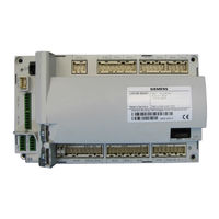
Siemens AGM60.4A9 Manual (30 pages)
Basic unit with integrated fuel-air ratio control for forced draft burners
Brand:
Siemens
| Category:
Controller
| Size: 2.46 MB
Advertisement
Related Products
Siemens SIRIUS ACT 3SU1
Siemens A80485-1
Siemens MOBY I ASM 421
Siemens SITRANS AW 7MP3112 Series
Siemens Add 7 AddFEM
Siemens SIRIUS ACT 3SU18 N Series
Siemens SIRIUS ACT 3SU140 E N Series
Siemens SIRIUS ACT 3SU14
Siemens AZL2 Series
Siemens SIDOOR ATD4 W Series
Siemens Categories
Industrial Equipment
Controller
Control Unit
Oven
Washer
More Siemens Manuals
Login
Sign In
OR
Sign in with Facebook
Sign in with Google
Upload manual
Upload from disk
Upload from URL