Sign In
Upload
Manuals
Brands
Siemens Manuals
Servo Drives
SINAMICS S200
Siemens SINAMICS S200 Manuals
Manuals and User Guides for Siemens SINAMICS S200. We have
2
Siemens SINAMICS S200 manuals available for free PDF download: Operating Instructions Manual, Compact Operating Instructions
Siemens SINAMICS S200 Operating Instructions Manual (764 pages)
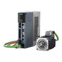
Pulse train servo drive system
Brand:
Siemens
| Category:
Servo Drives
| Size: 23.42 MB
Table of Contents
Table of Contents
5
Introduction
15
About SINAMICS
15
About this Manual
16
Content
16
Target Group
16
Standard Scope
17
Use of Third-Party Products in this Documentation
17
Websites of Third-Party Companies
17
SINAMICS Documentation
18
Service and Support
19
Siemens Industry Online Support on the Web
19
Spare Parts Services
19
Important Product Information
20
Intended Use
20
Firmware Updates and Constraints
21
Open-Source Software (OSS)
21
Compliance with the General Data Protection Regulation
22
Fundamental Safety Instructions
23
General Safety Instructions
23
Equipment Damage Due to Electric Fields or Electrostatic Discharge
31
Warranty and Liability for Application Examples
32
Cybersecurity Information
33
Residual Risks of Power Drive Systems
34
Description
37
System Overview
37
Converter
41
Motor
42
MOTION-CONNECT 350 and 380 Cables
42
Scope of Delivery
43
Converter
43
Rating Plate
44
Article Number Explanation
45
Serial Number Explanation
46
Motor
47
Rating Plate
48
Article Number Explanation
50
Serial Number Explanation
51
MOTION-CONNECT 350 and 380 Cables
52
Overview
52
Article Number Explanation
53
Device Combinations
54
200 V Servo Drive System
54
400 V Servo Drive System
55
Accessories
57
Connector Kits
57
Cables and Connectors
58
MOTION-CONNECT Cables and Connectors
58
Setpoint Cables and Connectors
61
Line Filters
61
Technical Data
62
Dimension Drawing
63
Mounting Instructions for the Line Filter
67
External 24 V DC Power Supply
68
Replacement Fans
68
Shield Plate Kit
69
SD Card
70
Directives and Standards
71
Directives, Standards and Certificates for the Converter
71
Directives, Standards and Certificates for the Motor
72
Directives, Standards and Certificates for the MOTION-CONNECT Cable
74
Application Planning
77
Protection of Persons from Electromagnetic Fields
77
Fault Protection for the Motor Circuit
79
Permissible Mains Supply Network Configurations for Motors
80
Line Connection Conditions for the Converter with the Motor 1FL2
81
Removing the IT Screw for the Functional Grounding
82
Minimum Cross-Section of the Protective Conductors
84
Electromagnetic Compatibility (EMC)
86
Interference Caused by Electromagnetic Fields
86
EMC Environments in Residential and Industrial Areas
87
EMC Category
87
Harmonic Current Emissions
88
EMC Limit Values in South Korea
89
EMC-Compliant Installation
90
EMC Zones in the Control Cabinet
90
Shielding and Potential Equalization Inside the Control Cabinet
90
Potential Equalization between Control Cabinets
91
Electromechanical Components
91
EMC-Compliant Cable Routing
92
Shielded Cables for the Converter
93
Achievable EMC Category
94
Mounting
97
Converter
97
Mounting Instructions for the Converter
97
Mounting Position
97
Dimension Drawings and Drilling Dimensions
98
Dimension Drawing and Drilling Dimensions for the 200 V Converter
98
Dimension Drawing and Drilling Dimensions for the 400 V Converter
99
Minimum Clearances
99
Motor
101
Transporting and Lifting
101
Checklist Prior to Mounting
104
Safety Labels on the Motor
104
Mounting Instructions for the Motor
105
Mounting Position
106
Dimension Drawings for Motors
107
Dimension Drawing for the 1FL2 Motor, Shaft Height 20
107
Dimension Drawing for the 1FL2 Motor, Shaft Height 30
108
Dimension Drawing for the 1FL2 Motor, Shaft Height 40
109
Dimension Drawing for the 1FL2 Motor, Shaft Height 45
110
Dimension Drawing for the 1FL2 Motor, Shaft Height 48
111
Dimension Drawing for the 1FL2 Motor, Shaft Height 52
112
Dimension Drawing for the 1FL2 Motor, Shaft Height 65
113
Dimension Drawing for the 1FL2 Motor, Shaft Height 90
114
Mounting the Feather Key
115
Attaching Output Elements
116
Laying Cables in Cable Carriers (for MOTION-CONNECT 380 Only)
119
Connecting
123
System Connection
124
Overview of the Converter Interfaces
125
Cables and Connectors
126
Maximum Permissible Cable Lengths
126
Conductor Cross-Sections and Cable Lugs
126
Connecting the Mains Supply
128
Interface Description - X1
128
Wiring
128
Using Several Single-Phase Converters in Machines and Plants
129
Connecting the Motor
131
Routing Cables in Damp Environments
131
Connecting the Motor Power Interface
131
Interface Description - X2 (Converter Side)
131
Interface Description - Power Connector (Motor Side)
132
Wiring
134
Connecting the Motor Holding Brake
135
Interface Description (Converter Side)
135
Interface Description (Motor Side)
135
Wiring
136
Connecting the Encoder
139
Interface Description - X120 (Converter Side)
139
Interface Description (Motor Side)
139
Wiring
140
Rotating the Connectors at the Motor
141
Connecting the Braking Resistor
144
Interface Description - X1
144
Wiring
144
Connecting the 24 V DC Power Supply
147
Interface Description - X124
147
Wiring
147
Connecting the Inputs and Outputs
149
Interface Description - X132
149
Wiring
151
Wiring of Digital Inputs
151
Wiring of Digital Outputs
152
Wiring of Analog Inputs
154
Wiring of Analog Outputs
156
Wiring of Pulse Train Inputs
156
Wiring of Pulse Train Outputs
158
Connection Examples with SIMATIC S7-1200
159
Connecting STO (for S200 PTI Only)
163
Interface Description - X131
163
Wiring
163
Connecting the Service Interface (Ethernet)
165
Interface Description - X127
165
Commissioning (Web Server)
167
Introduction
167
Fundamentals
168
Supported Operating Units
168
Requirements for Commissioning
168
Supported Browsers
168
Communication Interface
169
Making the Operating Instructions Available for the Web Server Information System
169
Using the Web Server Information System
171
Reloading
174
Getting Started
175
Calling the Web Server
175
Settings for Brand-New Converters
175
Basic Settings
176
Security Settings
176
Functions and Menus
179
Home Page
179
Commissioning
180
Complete Commissioning Workflow
180
Quick Setup
182
Testing the Converter Configuration
186
Optimization
187
Monitoring and Operation
189
Drive Status
189
Inputs/Outputs
191
Diagnostics
194
Messages
194
Diagnostic Buffer
197
Safety Integrated (for S200 PTI Only)
198
Connection Overview
199
Status Word and Control Word
199
Parameters
201
Parameter Lists
201
User-Defined Parameter List
203
Backup and Restore
203
Overview
203
Save Drive Data to Backup File
205
Scope of the Backup
205
Restoring Data from an Unencrypted Backup Data
206
Restoring Data from an Encrypted Backup Data
208
Restore Factory Settings
211
System
212
Settings
212
User Management
213
Protection & Security
215
Licenses
217
Firmware Update
219
About Web Server
219
Support
220
Control Panel
221
Series Commissioning
223
Series Commissioning with SD Card
224
Series Commissioning Using the Web Server
225
Functions
227
Overview of the Functions
227
Compound Controls
229
Inputs/Outputs
230
Digital Inputs
230
Digital Outputs
233
Analog Inputs
236
Analog Outputs
237
General Functions
239
Servo-On
239
Over-Travel
239
Stopping Methods at Servo-Off
241
Vertical Axis
242
PTO Function
243
Setting Motor Overload Protection in Accordance with UL 61800-5-1 Ed.2
244
Fast Position Control with Pulse Train Input (Fast PTI)
246
Sequence of SON
246
Selecting a Setpoint Pulse Train Input Channel
246
Selecting a Setpoint Pulse Train Input Form
247
Position Monitoring Function
248
Smoothing Function
252
Electronic Gear Ratio
253
Inhibiting Pulse Train Input Setpoint (P-TRG)
256
Clearing Droop Pulses (CLR)
256
Speed Limit
258
Torque Limit
260
Torque Overload Monitoring
262
Speed Control (S) (for S200 PTI Only)
263
Speed Setpoint
263
Direction and Stop
264
Speed Limit
265
Speed Reached Monitoring
267
Torque Limit
268
Torque Overload Monitoring
270
Zero Speed Clamp
271
Ramp-Function Generator
271
Torque Control (T) (for S200 PTI Only)
275
Torque Setpoint
275
Direction and Stop
276
Speed Limit
277
Torque Limit
279
Torque Overload Monitoring
281
Protective Speed Limit
282
Safety Integrated (for S200 PTI Only)
284
Safety Integrated Functions
285
Certification
286
PFH Values
286
Usage Time
287
Stop Functions
287
Safe Torque off (STO)
287
Functional Features of STO
289
Discrepancy Time
290
Input Filter
291
Self-Test of the Fail-Safe Digital Input (F-DI)
291
Safety Integrated Function Status/Diagnostics
292
Responses to Safety Messages
292
Stop Responses
292
Fail-Safe Acknowledgement of Safety Messages
293
Response Time
294
Functional Safety
294
Machinery Directive
295
Tuning
297
Tuning Workflow
297
Autotuning
298
One Button Tuning
299
Real Time Tuning (Online Tuning)
300
Manual Tuning
301
Control Loops
301
Servo Gain Adjustment
303
Gain Switching
304
PI/P Switching
307
Resonance Suppression
311
System Messages
315
SDI Status
315
SDI Status Overview
315
Status Display Via Leds
316
SDI Status Display
318
Function Buttons
320
System Runtime
321
Faults and Alarms
322
Overview of Faults and Alarms
322
Faults
323
Alarms
324
Explanation of the List of Faults and Alarms
324
List of Fault Codes and Alarm Codes
330
Corrective Maintenance
483
Service and Maintenance for the Converter
483
Restoring the Converter to Factory Settings
483
Restoring Factory Settings Via a Commissioning Tool
483
Reset of All User-Defined Settings to the Factory Setting Via an SD Card
483
Converter Firmware Update
485
Overview of Firmware Update
485
Firmware Update Via an SD Card
485
Replacing the Converter
486
Restoring the Drive Data Via the Web Server
489
Restoring Data from an Unencrypted Backup File
490
Restoring Data from an Encrypted Backup File
492
Forming the DC Link Capacitors
494
Service and Maintenance for the Motor
496
Replacing the Motor Bearings
498
Replacing the Motor
499
Service and Maintenance for Spare Parts
501
Spare Parts and Spare Parts Compatibility
501
Replacing the Fan Unit (400 V Converters FSC and FSD Only)
501
Device Disposal
504
Technical Data
505
Technical Data of the Converter
505
Permissible Environmental Conditions for the Converter
505
General Technical Data
506
Specific Data of the 200 V Converters
509
Specific Data of the 400 V Converters
510
Overload Capacity
512
Power Derating as a Function of the Installation Altitude and Ambient Temperature
514
Advertisement
Siemens SINAMICS S200 Compact Operating Instructions (36 pages)
Brand:
Siemens
| Category:
Servo Drives
| Size: 2.77 MB
Table of Contents
Table of Contents
4
Safety Notes
5
Technical Data
5
Technical Data of the Converter
5
Permissible Climatic Conditions for the Converter
5
Specific Technical Data of the 200 V Converter
6
Specific Technical Data of the 400 V Converter
6
Technical Data of the 1FL2 Motor
7
Technical Data of the MOTION-CONNECT Cables
7
Mounting
8
Mounting the Converter
8
Mounting Conditions
8
Dimension Drawings and Drill Dimensions
8
Minimum Clearance
9
Mounting the Motor
10
Mounting Instructions for the Motor
10
Lifting the Motor
11
Non-Thermally Insulated Mounting
11
Mounting the Feather Key
12
Attaching Output Elements
12
Lubricating the Shaft Sealing Ring
14
Routing Cables in Damp Environments
14
Connecting
14
System Overview
15
Overview of the Converter Interfaces
17
MOTION-CONNECT Cables
18
System Connection
19
Conductor Cross-Sections and Cable Lugs
19
Connecting the Mains Supply and Braking Resistor - X1
19
Connecting the Motor Power - X2
20
Connecting the Motor Holding Brake - X108
21
Connecting the Encoder - X120
22
Connecting the 24 V DC Power Supply - X124
23
Connecting the Service Interface - X127
23
Connecting the Inputs and Outputs - X130
23
Connecting STO - X131 (for the S200 Converter Only)
23
Connecting to the Fieldbus - X150
24
Block Diagram
24
Commissioning with Web Server
25
Supported Hardware and Software
25
Preparing for Commissioning
25
Configuring the Fundamental Settings
26
Structure of the Web Server
27
Performing Quick Setup
29
Performing One Button Tuning
31
Diagnostics and Monitoring
32
Diagnostics and Monitoring with SINAMICS SDI Status
32
Fault Causes and Remedial Measures for the Motor
33
Additional Information
34
Advertisement
Related Products
Siemens SINAMICS S210
Siemens SIMOTICS S-1FK2
Siemens SINAMIC S120
Siemens SIMATIC MICRO-DRIVE
Siemens SIMOTICS S-1FL2
Siemens SINAMICS/SIMOTICS S200
Siemens SINAMICS SIMOTICS S200 PROFINET
Siemens sinamics V60 CPM60.1
Siemens S223
SIEMENS S25
Siemens Categories
Industrial Equipment
Controller
Control Unit
Oven
Washer
More Siemens Manuals
Login
Sign In
OR
Sign in with Facebook
Sign in with Google
Upload manual
Upload from disk
Upload from URL