Sign In
Upload
Manuals
Brands
Siemens Manuals
Control Systems
SINUMERIK 828D PPU Series
Siemens SINUMERIK 828D PPU Series Manuals
Manuals and User Guides for Siemens SINUMERIK 828D PPU Series. We have
3
Siemens SINUMERIK 828D PPU Series manuals available for free PDF download: Software And Hardware Service Manual, Manual
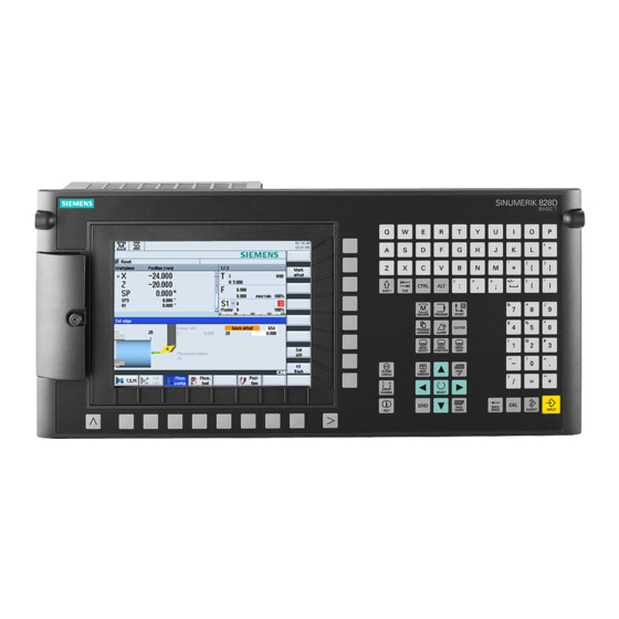
Siemens SINUMERIK 828D PPU Series Software And Hardware Service Manual (246 pages)
Brand:
Siemens
| Category:
Control Unit
| Size: 31.24 MB
Table of Contents
Preface
3
Table of Contents
5
1 Fundamental Safety Instructions
11
General Safety Instructions
11
Equipment Damage Due to Electric Fields or Electrostatic Discharge
15
Warranty and Liability for Application Examples
16
Industrial Security
17
Residual Risks of Power Drive Systems
19
2 System Description
21
System Overview
21
PPU Versions
24
3 Service Cases - Software
27
Backing up User Data
29
This Is How You Backup User Data
29
This Is How You Load the User Data Backup
32
Generating a Commissioning Archive
35
This Is How You Generate a Setup Archive on an External Data Storage Medium
35
This Is How You Read a Setup Archive from an External Data Storage Medium
38
This Is How You Generate a Setup Archive on the System Compactflash Card
40
This Is How You Read in a Setup Archive from the System Compactflash Card
41
Software Backup
44
This Is How You Generate a Software Backup
44
This Is How You Install a Software Backup
47
Updating the Software
52
Generating a Boot System on the Compactflash Card
56
This Is How You Create a Boot System
56
This Is How You Install a Software Backup Using the Boot System
59
Licensing
62
Licensing after Replacing the System Compactflash Card
62
This Is How You License a CNC Option
62
This Is How You Determine Missing Licenses/Options
64
This Is How You Generated a New License Key
65
This Is How You Display the Actual License Key
68
Machine Registration
71
This Is How You Generate the Machine Logbook
71
This Is How You Make a New Entry in the Logbook
73
This Is How You Save the Machine Identity
75
This Is How You Send the Machine Identity
77
Service and Diagnostics
78
Backing up Log Data for Service Case
78
Overview
78
Backing up Log Data to USB
78
Backing up Log Data as ZIP File
78
4 Service Cases - Hardware
79
Safety Instructions for the Hardware
81
PPU 27X.4
83
PPU Status Displays
83
This Is How You Remove the PPU
85
This Is How You Install the PPU
86
Replacing the System Compactflash Card
88
This Is How You Remove the System Compactflash Card
88
This Is How You Insert the System Compactflash Card
89
Replacing the Front Cover
91
This Is How You Remove the Front Cover
91
This Is How You Install the Front Cover
92
Machine Control Panels
93
This Is How You Remove MCP 483 USB/MCP 310 USB/MCP 416 USB
93
This Is How You Install the MCP 483 USB/MCP 310 USB/MCP 416 USB
95
Status Display MCP Interface PN
96
This Is How You Remove the MCP Interface PN
96
This Is How You Install the MCP Interface PN
98
Status Displays, MCP 483C PN
99
This Is How You Remove the MCP 483C PN
100
This Is How You Install the MCP 483C PN
102
Status Displays MCP 310C PN
103
This Is How You Remove the MCP 310C PN
104
This Is How You Install the MCP 310C PN
106
This Is How You Replace the Rotary Switch
107
I/O Modules
110
Status Displays PP 72/48D PN
110
This Is How You Remove the PP 72/48D PN
111
This Is How You Install the PP 72/48D PN
113
Status Displays PP 72/48D 2/2A PN
114
This Is How You Remove the PP 72/48D 2/2A PN
115
This Is How You Install the PP 72/48D 2/2A PN
117
Expansion Modules NX10.3 / NX15.3
118
NX10.3 / NX15.3 Status Displays
118
NX10.3 / NX15.3 Connections
119
This Is How You Remove the NX10.3 / NX15.3
119
This Is How You Install the NX10.3 / NX15.3
121
Installing SINAMICS Components
122
Releasing with a Screwdriver
122
Protective Conductor Connection and Shield Contact
122
Control Unit CU320-2 PN and CU310-2 PN
124
CU320-2 PN Status Displays
124
CU320-2 PN Connections
127
This Is How You Remove the CU320-2 PN
128
This Is How You Install the CU320-2 PN
129
CU310-2 PN Status Displays
129
CU310-2 PN Connections
133
This Is How You Remove the CU310-2 PN
134
This Is How You Install the CU310-2 PN
136
SINAMICS S120 Combi
137
S120 Combi Status Displays
137
Connections, 3-Axis Module
139
Connections, 4-Axis Module
141
How to Mount an S120 Combi Power Module
142
This Is How You Attach the Drip Protection
144
This Is How You Remove the Front Panel
145
This Is How You Open the DC Link Cover
146
This Is How You Connect the DC Link Busbars and 24 V Busbars
149
To Connect the Second Component
152
This Is How You Remove the Internal Fan
154
This Is How You Install the Internal Fan
157
This Is How You Install the External Fan
158
This Is How You Clean the Heat Sink of the S120 Combi
162
Motor Module Booksize Compact Format
166
Motor Module Booksize Compact Status Displays
166
Motor Module Connections
167
This Is How You Mount a Motor Module Booksize Compact
169
This Is How You Replace the Fan on a Motor Module Booksize Compact
170
Single Motor Modules
174
SMM Status Displays
174
SMM Connections
175
This Is How You Remove a Motor Module
176
This Is How You Install a Motor Module
178
Double Motor Modules
181
DMM Status Displays
181
DMM Connections
182
This Is How You Remove a Motor Module
183
This Is How You Install a Motor Module
185
Smart Line Modules
188
SLM (< 16 Kw) Status Displays
188
SLM (< 16 Kw) Connections
189
SLM (16 Kw and Higher) Status Displays
190
SLM (16 Kw and Higher) Connections
191
This Is How You Remove an SLM
192
This Is How You Install an SLM
194
Active Line Modules
196
ALM Status Displays
196
ALM Connections
197
This Is How You Remove an ALM
198
This Is How You Install an ALM
200
Sensor Modules Cabinet
202
SMC10/SMC20 Status Displays
202
SMC10/SMC20 Connections
203
This Is How You Remove an SMC10/SMC20
203
This Is How You Install an SMC10/SMC20
205
SMC30 Status Displays
206
SMC30 Connections
207
This Is How You Remove an SMC30
207
This Is How You Install an SMC30
209
SMC40 Status Displays
210
SMC40 Connections
211
This Is How You Remove an SMC40
211
This Is How You Install an SMC40
213
Sensor Modules External
214
SME20 Connections
214
This Is How You Remove an SME20 and Install It Again
214
SME25 Connections
215
This Is How You Remove an SME25 and Install It Again
215
SME120 Connections
217
This Is How You Remove an SME120 and Install It Again
217
SME125 Connections
218
This Is How You Remove an SME125 and Install It Again
218
Terminal Modules
220
TM54F Status Displays
220
TM54F Connections
222
This Is How You Remove an TM54F
223
This Is How You Install a TM54F
224
TM120 Status Displays
224
TM120 Safety Instructions
225
TM120 Connections
226
This Is How You Remove a TM120 and Install It Again
227
Hub Modules
228
DMC20 Status Displays
228
DMC20 Connections
229
This Is How You Remove a DMC20
229
This Is How You Install a DMC20
230
DME20 Connections
231
This Is How You Mount a DME20
232
Connection to X524 Electronics Power Supply
233
Modem Md720
234
Status Displays MODEM MD720
234
Replace SIM Card
234
This Is How You Load the Factory Settings
235
5 Spare Parts and Accessories
237
Appendix
239
Abbreviations
239
Information about Third-Party Software Used
241
Documentation Overview SINUMERIK 828D
243
Advertisement
Siemens SINUMERIK 828D PPU Series Manual (244 pages)
Brand:
Siemens
| Category:
Control Unit
| Size: 13.88 MB
Table of Contents
Preface
3
Table of Contents
5
1 Safety Notes
9
Danger Notices
9
ESD Notices
11
2 System Description
13
Controller Features
13
PPU Version 24X.3 BASIC
15
PPU Versions 26X.3 and 28X.3
18
Operator Controls and Display Elements
21
Type Plate
22
System Overview
24
Connectable Components
26
Ordering Data
27
Compactflash Cards
29
Compactflash Card System
29
Inserting the System Compactflash Card
30
Compactflash Card for User Data
32
3 Application Planning
35
Secondary Electrical Conditions
35
Protective Separation as Per en 61800-5-1
35
Grounding Concept
35
RI Suppression Measures
37
Climatic and Mechanical Environmental Conditions
39
Ambient Conditions
39
Transport and Storage Conditions
39
Operating Conditions
40
Recycling and Disposal
41
4 Installing
43
Mounting Positions
43
Dimension Drawings
50
5 Rules for Permitted Topologies
53
Topology Rules for S120 Combi
53
Topology Rules for S120 Booksize
54
Topology Rules for Safety Integrated Functions
58
Topology Example Without Safety Integrated Functions
59
Topology Example with Safety Integrated Functions
63
6 Interface Description
67
Interface Overview
67
Power Supply Connection
69
Requirements for the Power Supply
69
Connecting the Power Supply
71
Ethernet
71
PLC I/O Interface Based on PROFINET
73
Addressing the I/O Modules
75
Digital Inputs/Outputs
76
Terminal Connection Diagram
81
Example: Connecting an Inductive Proximity Switch (Beros)
82
Technical Data
83
DRIVE-Cliq
84
DRIVE-Cliq Interface
84
SINAMICS Components
86
Handwheel
87
Usb
89
RS 232 Serial Interface
90
7 Connectable Components
93
Mcp 483C Pn
93
Operator Controls and Display Elements
94
Mounting
97
Connecting
98
Parameterization
104
Technical Data
107
Spare Parts and Accessories
108
Mcp 310C Pn
111
Operator Controls and Display Elements
113
Mounting
116
Connecting
118
Parameterization
123
Technical Data
126
Spare Parts and Accessories
127
MCP Interface PN
130
Mounting
133
Connection
134
Parameter Assignment
146
Technical Data
148
Electronic Handwheel
148
Description
148
Mounting
151
Connection
152
Technical Specifications
153
Spare Parts and Accessories
154
Mini Handheld Unit
154
Description
154
Mounting
157
Connecting
160
Parameterization
162
Technical Data
163
Spare Parts and Accessories
164
Pp 72/48D Pn
166
Description
166
Mounting
169
Connecting
171
X1 Power Supply
172
X2 Profinet
173
X111, X222 and X333 Pin Assignment
174
Specification of the Digital Inputs
177
Specification of the Digital Outputs
178
Parameter Assignment
179
Input / Output Images
179
Diagnostics Via Input Image
181
Technical Data
183
Pp 72/48D 2/2A Pn
184
Description
184
Assembling
187
Connection
189
X1 Power Supply
190
X2 Profinet
193
X111, X222 and X333 Pin Assignment
194
Specification of the Digital Inputs
197
Specification of the Digital Outputs
198
Analog X3 Inputs/Outputs
199
Assigning Parameters
203
Input / Output Images
203
Diagnostics Via Input Image
205
Assigning Parameters to the Analog Inputs / Outputs
207
Analog Value Representation
209
Examples
212
Technical Data
213
Description
214
Nx10.3
214
Mounting
217
Connecting
219
Technical Data
223
8 Technical Data
225
9 Spare Parts and Accessories
227
SINAUT Modem
227
PN/PN Coupler
229
Principle of Operation
229
Configuration
230
Sentron Pac3200/Pac4200
233
SITOP Power Supply
235
Terminal Strip Converter
236
Appendix
237
Abbreviations
237
Documentation Overview SINUMERIK 828D
239
Index
241
Siemens SINUMERIK 828D PPU Series Manual (230 pages)
Brand:
Siemens
| Category:
Control Systems
| Size: 7.97 MB
Table of Contents
Preface
3
Table of Contents
7
1 Safety Notes
11
Danger Notices
11
ESD Notices
13
2 System Overview
15
Variants
20
Ordering Data
22
3 Description
25
Features
25
Layout
26
Type Plate
30
Operator Controls and Display Elements
31
Keyboard and Display
31
LED Front Displays
33
Compactflash Card
34
Compactflash Card with System Software and for User Data
34
Inserting the System Compactflash Card
35
4 Application Planning
39
Secondary Electrical Conditions
39
Protective Separation as Per en 61800-5-1
39
Grounding Concept
39
RI Suppression Measures
41
Climatic and Mechanical Environmental Conditions
43
Ambient Conditions
43
Transport and Storage Conditions
44
Operating Conditions
45
Recycling and Disposal
47
5 Installation
49
Safety Notes
49
Designs
50
Dimension Drawings
57
6 Connecting
59
Interface Overview
59
Addressing the I/O Modules
62
Power Supply Connection
63
Requirements for the Power Supply
63
Connecting the Power Supply
64
DRIVE-Cliq
66
SINAMICS Components that Can be Connected
68
Topology Rules for S120 Combi
69
Topology Rules for S120 Booksize
71
Topology Rules for Safety Integrated Functions
75
Topology Example Without Safety Integrated Functions
76
Topology Example with Safety Integrated Functions
79
PLC I/O Interface
83
Ethernet
85
Digital Inputs/Outputs
87
Terminal Connection Diagram
90
Technical Data
91
Handwheel
93
Usb
94
Rs232
95
7 Connectable Components
97
Mcp 483C Pn
97
Operator Controls and Display Elements
98
Mounting
102
Dimension Drawing
102
Replacing the Rotary Switch
104
Connecting
106
Description
106
Input / Output Images
112
Technical Data
115
Spare Parts and Accessories
116
Mcp 310C Pn
117
Description
117
Operator Controls and Display Elements
118
Mounting
122
Dimension Drawing
122
Replacing the Rotary Switch
124
Connecting
126
Description
126
Input / Output Images
132
Technical Data
135
Spare Parts and Accessories
136
Mini Handheld Unit
137
Description
137
Operator Controls
138
Connecting
141
Parameter Assignment
146
Technical Data
147
Spare Parts and Accessories
148
Pp 72/48D Pn
149
Description
149
Mounting
152
Connecting
154
Interfaces
154
X1 Power Supply
155
X2 Profinet
156
X111, X222 and X333 Digital Inputs/Outputs
158
Parameter Assignment
164
Input / Output Images
164
Diagnostics Via Input Image
167
Technical Data
169
Pp 72/48D 2/2A Pn
170
Description
170
Assembling
173
Connection
174
I/O Module
174
Interface Overview
174
X1 Power Supply
175
X2 Profinet
178
X111, X222 and X333 Digital Inputs/Outputs
180
Analog X3 Inputs/Outputs
186
Assigning Parameters
191
Input / Output Images
191
Assigning Parameters to the Analog Inputs / Outputs
193
Analog Value Representation
195
Examples
198
Diagnostics Via Input Image
199
Technical Data
202
Description
203
Nx10.3
203
Mounting
206
Connecting
209
Technical Data
213
PN/PN Coupler
214
Terminal Strip Converter
217
GSM Modem
218
8 Technical Data
221
Appendix
223
Abbreviations
223
A.1 Abbreviations
223
Overview
225
A.2 Overview
225
Index
227
Advertisement
Advertisement
Related Products
Siemens SINUMERIK 828D sl
Siemens SINUMERIK 808D
Siemens SINUMERIK 840DE
Siemens SINUMERIK 840DiE
Siemens SINUMERIK 840DE SL
Siemens SINUMERIK 808D sl
Siemens SINUMERIK 802S
Siemens SINUMERIK 802C
Siemens Sinumerik 801
Siemens YASKAWA 830DI
Siemens Categories
Industrial Equipment
Controller
Control Unit
Oven
Washer
More Siemens Manuals
Login
Sign In
OR
Sign in with Facebook
Sign in with Google
Upload manual
Upload from disk
Upload from URL