Sign In
Upload
Manuals
Brands
Siemens Manuals
Control Unit
SIRIUS
Siemens SIRIUS Manuals
Manuals and User Guides for Siemens SIRIUS. We have
13
Siemens SIRIUS manuals available for free PDF download: System Manual, Manual, Configuration Manual, Original Operating Instructions, Operating Instructions Manual, Operating Instructions
Siemens SIRIUS System Manual (425 pages)
Brand:
Siemens
| Category:
Relays
| Size: 29.75 MB
Table of Contents
Table of Contents
4
Figure 1-1: SIRIUS System
21
Figure 1-2: Circuit Breaker, Accessories (Frame Size S00)
22
Figure 1-3: Circuit Breakers, Accessories (Frame Sizes S0, S2, and S3)
22
Figure 1-4: Contactors, Accessories (Frame Size S00)
23
Figure 1-5: Contactors, Accessories (Frame Sizes S0 to S3)
24
Table 1-1: Components and Combinations with Accessories
28
Figure 1-6: Device Combinations
29
Figure 1-7: Contactor Combination for Reversing
30
Table 1-2: Mounting Methods
31
Table 1-3: Mounting the Device on the Rail
32
Table 1-4: Removing the Device from the Rail
32
Table 1-5: How to Use a Cage Clamp Terminal
35
Table 1-6: Connection Cross-Section for Frame Size S00
36
Table 1-7: Connection Cross-Section for Frame Size S0
36
Figure 1-9: Conductor Cross-Sections £ 1 MM²
36
Table 1-8: Connection Cross-Section for Frame Size S2
37
Figure 1-8: Cage Clamp Terminal
37
Table 1-9: Connection Cross-Section for Frame Size S3
37
Figure 1-10: Communication
38
Specifications/Regulations/Approvals
46
Utilization Categories
46
Table 2-1: Circuit Breakers, Frame Sizes
48
Figure 2-2: Setting the Current Setting I
50
Figure 2-3: Sealing the Adjustment Scale (Frame Size S00)
51
Table 2-2: Contact Position Indicators of the Circuit Breakers
52
Figure 2-4: Tripped Position, 3RV (Frame Size S0)
52
Figure 2-5: Locking the Toggle Switch (Frame Size S00)
52
Table 2-3: Testing Overload Tripping (Example: Frame Size S00)
53
Figure 2-6: Time-Current Characteristic, Chart
54
Figure 2-7: Frequency Sensitivity of the N-Short-Circuit Releases
55
Figure 2-8: Circuit Breaker with Overload Relay Function (Frame Sizes S0 to S3)
57
Figure 2-9: Circuit Diagrams of Circuit Breakers for Fuse Monitoring
58
Table 2-4: Suggestions for Switching Direct Current
59
Table 2-5: Attachable Accessories
62
Figure 2-10: Mounting the Transverse Auxiliary Switch (Frame Size S00)
62
Table 2-6: Voltage Ranges of the Auxiliary Releases
63
Figure 2-11: Mounting/Removing the Lateral Auxiliary Switch/Undervoltage Release (Frame Size S00)
63
Table 2-7: Testing Overload Tripping (Example: Frame Size S0)
64
Table 2-8: Alarm Switch with Tripped Signal and Short Circuit Signal
65
Table 2-9: Mounting the Remote-Control Mechanism (Frame Size S2)
68
Figure 2-12: Mounting the Disconnecting Module (Frame Size S0)
69
Figure 2-13: Locking the Disconnecting Module (Frame Size S0)
70
Figure 2-14: Locking the Disconnecting Module and Mounting the Cover (Frame Size S2)
70
Figure 2-15: Mounting the Rotary Switch Extension for the Door (Frame Size S2)
71
Table 2-10: Opening a Cubicle Door Using the Rotary Switch Extension
72
Figure 2-16: Operating the Rotary Switch Extension for the Door
72
Table 2-11: Mounting the Extension Shaft
73
Figure 2-17: Locking the Rotary Switch Extension for the Door
73
Figure 2-18: Terminals for "Combination Motor Controller Type E
74
Table 2-12: Housings for Circuit Breakers
75
Figure 2-19: Molded-Plastic Surface Casing (Frame Size S00)
75
Table 2-13: Front Plates for any Housings
76
Figure 2-20: Molded-Plastic Bay (Frame Size S00)
76
Figure 2-21: Mounting the Front Plate (Frame Size S00)
77
Figure 2-22: Mounting the Front Plate (Frame Size S0)
77
Figure 2-23: Accessories for the Housings and Front Plates (Frame Size S00)
78
Figure 2-24: Indicator Light Installation in a Molded-Plastic Housing
79
Table 2-14: Busbar Systems
80
Table 2-15: Dimensions of the Busbar Adapters and Accessories
80
Table 2-16: Link Modules for Connecting Circuit Breakers to Contactors
81
Figure 2-25: Mounting Circuit Breakers on Busbar Adapters (Frame Sizes S00 and S0)
81
Figure 2-26: Mounting Circuit Breakers on Busbar Adapters (Frame Sizes S2 and S3)
82
Figure 2-27: Accessories for Busbar Adapters (Frame Sizes S00 to S2)
83
Table 2-17: Rated Operational Voltage/Current
84
Table 2-18: Types of 3-Phase Busbars
84
Figure 2-28: 3-Phase Busbar System
84
Table 2-19: Conductor Cross-Section of the 3-Phase Feed-In Terminals
85
Figure 2-29: Mounting the Isolated 3-Phase Busbar System (Frame Sizes S00 to S0)
86
Figure 2-30: Mounting the Isolated 3-Phase Busbar System (Frame Size S2)
87
Figure 2-31: Mounting the Circuit Breakers Onto the Rail
88
Figure 2-32: Screw-On Mounting of the 3RV1 (Example: Frame Size S00)
88
Figure 2-33: Circuit Breaker, Soldering Pin Connector (Frame Size S00)
90
Figure 2-34: Device Circuit Diagram (Frame Size S00)
91
Figure 2-35: Device Circuit Diagrams (Frame Sizes S0 to S3)
91
Figure 2-36: Circuit Breaker with Relay Function, Device Circuit Diagrams (Frame Sizes S0 to S3)
91
Figure 2-38: 3RV10 31 (Frame Size S2)
92
Figure 2-39: 3RV10 4 (Frame Size S3)
92
Figure 2-46: 3RV19 13-4C (Frame Size S00)
95
Figure 2-47: 3RV19 23-4. (Frame Sizes S0, S2, S3)
95
Figure 2-48: 3RV19 18-5A/-5B (Frame Size S00)
96
Figure 2-49: 3RV19 26-0 (Frame Sizes S0, S2, S3)
96
Figure 2-50: 3RV19 28-1H (Frame Size S0) and 3RT19 46-4GA07 (Frame Size S3)
96
Figure 2-51: 3RV19. 6-3AP0 for Circuit Breaker
97
Figure 2-54: 3RV19 15-1. (Frame Sizes S00, S0)
98
Figure 2-55: 3RV19 35-1 (for Circuit Breakers in Frame Size S2)
99
Figure 2-56: 3RV19 35-3 (for Circuit Breakers in Frame Size S2)
99
Figure 2-58: 3RV19 35-5A 3RV19 15-5D
100
Table 3-5: Safe Isolation
109
Table 3-33: Covers
110
Table 3-1: Utilization Categories, Test Conditions for AC Voltage
112
Table 3-2: Utilization Categories, Test Conditions for DC Voltages
113
Table 3-3: Utilization Categories, Test Conditions for AC Voltage (Auxiliary Contact Elements)
113
Table 3-4: Utilization Categories, Test Conditions for DC Voltage (Auxiliary Contact Elements)
114
Positively Driven Operation
115
Safe Isolation
115
Explanation of Terms
117
Device Description
118
Figure 3-1: Frame Sizes of the 3RT1 Contactors
118
Table 3-6: Performance Ranges of the 3RT10 Contactors
118
Table 3-7: Types of 3RT/3RH Contactors
119
Actuating Systems
120
Short-Circuit Protection of the SIRIUS Contactors
120
Table 3-8: Actuating Systems
120
Operation
121
General Information
121
Contact Reliability
122
Figure 3-2: Contact Areas
123
Figure 3-3: Characteristic Curve of the Electrical Service Life of the Main Contacts (Frame Size S00)
125
Figure 3-4: Characteristic Curve of the Electrical Service Life of the Main Contacts (Frame Size S0)
125
Figure 3-5: Characteristic Curve of the Electrical Service Life of the Main Contacts (Frame Size S2)
126
Figure 3-6: Characteristic Curve of the Electrical Service Life of the Main Contacts (Frame Size S3)
126
Figure 3-7: Characteristic Curve of the Electrical Service Life of the Auxiliary Contacts
127
Application and Areas of Use
128
3RT10 Contactors with 3 Main Contacts for Switching Motors
128
3RT1446 Contactors with 3 Main Contacts for Switching Resistive Loads (AC-1)
129
Table 3-10: Comparison between the 3RT1446 and 3RT1046 Contactors
129
3RT13 and 3RT15 Contactors with 4 Main Contacts
130
Table 3-11: Applications of 4-Pole Contactors
130
Table 3-12: 4-Pole Contactors and Auxiliary Contacts
130
Table 3-13: 4-Pole Reversing Contactor Combination with Front Interlock (Frame Size S0)
131
Table 3-14: 4-Pole Reversing Contactor Combination with Lateral Interlock (Frame Size S0)
132
Table 3-15: 4-Pole Reversing Contactor Combination (Frame Sizes S2 and S3)
132
3RT16 Capacitor-Switching Contactors for Switching Capacitors
133
Contactors with an Extended Operating Range
134
Figure 3-9: Capacitor-Switching Contactors, Circuit Diagram
134
Contactors with an Extended Operating Range (3RH11
135
Figure 3-10: Contactors with an Extended Operating Range, Circuit Diagrams
136
Figure 3-11: Contactors with an Extended Operating Range, Terminal Markings
136
Figure 3-12: Contactors with an Extended Operating Range, Circuit Diagram
136
Contactors with an Extended Operating Range (3RH1122-2K.40, 3RT1017-2K.4., 3RT102.-3K.40)
137
3RH1 Auxiliary Contactors
137
3RT10 Contactor Relays for Switching Motors (Interface) and 3RH11 Contactor Relays for Switching Auxiliary Circuits
138
Figure 3-13: Contactor Relays: Voltage Ranges
139
Contactor Combinations for Reversing
140
Figure 3-14: Fully Assembled Contactor Combination for Reversing (Frame Sizes S00 and S0)
140
Figure 3-15: Star-Delta Combination, Locking Device at the Front (Frame Size S0)
142
Figure 3-16: Star-Delta Combination, Locking Devices at the Front (Frame Sizes S2/S3)
142
Table 3-16: Assembling the Contactor Combination for Reversing (Frame Size S00)
143
Table 3-17: Assembling the Contactor Combination for Reversing (Frame Size S0)
144
Table 3-18: Assembling the Contactor Combination for Reversing (Frame Sizes S2/S3)
145
Figure 3-17: 4-Pole Contactor Combination for Reversing (Frame Size S0)
146
Figure 3-18: 4-Pole Contactor Combination for Reversing (Frame Size S2)
147
Figure 3-19: NC Contact Interlock (Frame Size S00)
147
Figure 3-20: Contactor Combination for Reversing, Main Circuit (Frame Sizes S00 to S3)
148
Figure 3-21: Contactor Combination for Reversing, Control Circuit (Frame Size S00)
148
Star-Delta Combinations
149
Figure 3-22: Contactor Combination for Reversing, Control Circuit (Frame Sizes S0 to S3)
149
Figure 3-23: Star-Delta Combinations (Frame Sizes S00, S0, S3)
150
Figure 3-24: Star-Delta Combination (Frame Size S2)
151
Table 3-19: Configuration of the Star-Delta Combinations
152
Table 3-20: Assembly of the Star-Delta Combination in Frame Size S00
153
Table 3-21: Assembly of the Star-Delta Combinations in Frame Sizes S0 to S3
154
Figure 3-25: Star-Delta Combination, Main Circuit (Frame Sizes S00 to S3)
155
Figure 3-26: Star-Delta Combination, Control Circuit (Frame Size S00)
156
Figure 3-27: Star-Delta Combination, Control Circuit (Frame Sizes S0 to S3)
156
Accessories
157
Figure 3-28: Accessories for Contactors of Frame Size S00
157
Figure 3-29: Accessories for Auxiliary Contactors/Contactor Relays of Frame Size S00
158
Figure 3-30: Accessories for Contactors of Frame Size S00
159
Attachable Auxiliary Switches for Extending the Auxiliary Contacts
160
Table 3-23: Expansion Options for Auxiliary Switch Blocks
162
Figure 3-31: Auxiliary Switch at Front
162
Table 3-24: Possible Auxiliary Switch Combinations (Frame Size S0/S2)
163
Table 3-25: Possible Auxiliary Switch Combinations (Frame Size S3)
163
Figure 3-32: Auxiliary Switch at Side
163
Table 3-26: Possible Auxiliary Switch Combinations with 4-Pole/Capacitor-Switching Contactors
164
Table 3-27: Auxiliary Switches with Make-Before-Break Contacting
164
Figure 3-33: Switching of the Auxiliary Contact Elements
164
Terminal Markings of the Contactors (Frame Sizes S00 to S3)
165
Figure 3-34: Auxiliary Contacts, Contactors for Switching Motors (Frame Size S00)
166
Figure 3-35: Auxiliary Contacts, Contactors for Switching Motors (Frame Sizes S0 to S3)
167
Table 3-22: Auxiliary Switch Blocks
167
Terminal Markings of the Contactors and Auxiliary Contactors Combined with Auxiliary Switch Blocks
167
Figure 3-36: Graphical Symbols for Auxiliary Contact Elements in Acc. with en 50 012 (Excerpt)
168
Figure 3-37: Device Circuit Diagrams of the Auxiliary Switch Blocks (DIN en 50 012)
168
Figure 3-38: Auxiliary Contacts for Auxiliary Contactors
169
Auxiliary Switches that Can be Attached to 3RH1 Auxiliary Contactors
169
Figure 3-39: Graphical Symbols for Auxiliary Contactors in Acc. with en 50 011 (Excerpt)
170
Figure 3-40: Device Circuit Diagrams
171
Figure 3-41: Position Diagrams of the Auxiliary Switches (Frame Sizes S0 to S3)
171
Time-Delay Auxiliary Switches
172
Frame Size S00 (3RT1916-2E, -2F, -2G)
172
Figure 3-42: Time-Delay Auxiliary Switch Block (Frame Size S00)
173
Figure 3-43: Function Diagrams of the Time-Delay Auxiliary Switches (Frame Size S00)
173
Figure 3-44: Time-Delay Auxiliary Switch Block (Frame Sizes S0 to S3)
174
Frame Sizes S0 to S3 (3RT1926-2E, -2F, -2G)
174
Figure 3-45: Time-Delay Auxiliary Switches, Function Diagrams (Frame Sizes S0 to S3)
175
Solid-State Time Relay Blocks with Semiconductor Output
175
Figure 3-46: Control of Loads
176
Figure 3-47: Solid-State Time Relay Block with Semiconductor Output, Installation (Frame Size S00)
176
Frame Size S00 (3RT1916-2C, -2D)
176
Figure 3-48: Solid-State Time Relay Block with Semiconductor Output, Function Diagrams (Frame Size S00)
177
Figure 3-49: Solid-State Time Relay with Semiconductor Output, Circuit Diagrams (Frame Size S00)
177
Figure 3-50: Solid-State Time Relay with a Semiconductor Output, Installation (Frame Size S00)
177
Frame Size S0 to S3 (3RT1926-2C, -2D)
177
Figure 3-51: Solid-State Time Relay with Semiconductor Output, Circuit Diagrams
178
Figure 3-52: Solid-State Time Relay with Semiconductor Output, Function Diagrams
178
Additional Load Module (3RT1916-1GA00)
178
Figure 3-53: Coupling Link (Frame Sizes S0 to S3)
179
Coupling Element for Frame Sizes S0 to S3 (3RH1924-1GP11)
179
Figure 3-54: Coupling Link, Circuit Diagram (Frame Sizes S0 to S3)
180
Figure 3-55: Disconnecting an Unused Contactor Coil
181
Surge Suppression
181
Figure 3-56: Circuit with a Varistor (AC/DC Operation)
182
Figure 3-57: Circuit with an RC Element (AC/DC Operation)
182
Figure 3-58: Circuit with a Diode (AC/DC Operation)
183
Table 3-29: How Surge Suppressors Work
184
Figure 3-59: Surge Suppressors, Installation
185
Figure 3-60: RC Element/Varistor, Circuit Diagrams
186
Other Accessories
186
LED Module for Indicating Contactor Control (3RT1926-1QT00)
186
Table 3-30: Conductor Cross-Sections of 3-Pole Auxiliary Connecting Lead Terminals (for Frame Size S3)
187
Figure 3-61: LED Module
187
Auxiliary Connecting Lead Terminal, 3-Pole (for Frame Size S3)
187
EMC Module (3RT1916-1P
187
Figure 3-63: Soldering Pin Connection, Mounting
189
Figure 3-64: Mounting the Soldering Pin Connection on a 4-Pole Auxiliary Switch Block
189
Soldering Pin Connector for Frame Size S00
189
Figure 3-65: Removing the Spring from the Soldering Pin Connection
190
Table 3-31: Parallel Links Making and Breaking Capacity
191
Parallel Connections
191
Table 3-32: Parallel Connections Variants
192
Covers for Frame Sizes S2 and S3
192
Figure 3-66: Terminal Covers
193
Table 3-34: Attachment
194
Figure 3-67: 3RT: Screw-On Attachment (Frame Size S00)
194
Mounting and Connection
194
Mounting
194
Figure 3-68: Snap-On Attachment
195
Figure 3-69: Installation Positions
195
Table 3-35: Vertical Installation Position
196
Connection
196
Figure 3-70: Cage Clamp Terminals
197
Figure 3-71: Insulation Stop with Cage Clamp Terminals
197
Table 3-36: Conductor Cross-Sections (Frame Sizes S00 to S3)
199
Figure 3-72: Replacing the Magnet Coil (Frame Size S0/AC)
200
Changing the Magnet Coils
200
Figure 3-73: Replacing the Magnet Coil (Frame Size S2/AC)
201
Figure 3-74: Replacing the Magnet Coil (Frame Size S2/DC)
202
Figure 3-75: Replacing the Magnet Coil (Frame Size S3/AC)
203
Figure 3-76: Replacing the Magnet Coil (Frame Size S3/DC)
204
Figure 3-77: Replacing the Contact Piece (Frame Size S2)
205
Changing the Contact Piece
205
Figure 3-78: Replacing the Contact Piece (Frame Size S3)
206
Figure 3-79: Contact Pieces (Frame Sizes S2/S3)
206
Dimensioned Drawings (Dimensions in MM)
207
Figure 3-80: 3RT1. 10 1/3RH11 Contactors (Frame Size S00)
207
Figure 3-81: 3RT10 2 Contactors, 3RT10 2 Contactor Relays (Frame Size S0)
207
Figure 3-82: 3RT10 3 (Frame Size S2)
208
Figure 3-83: 3RT10 4, 3RT14 46 (Frame Size S3)
208
Figure 3-86: 3RT13 2, 3RT15 2 (Frame Size S0)
209
Figure 3-84: 3RT10 1 (Frame Size S00)
209
Figure 3-85: 3RT13 1, 3RT15 1 (Frame Size S00)
209
Figure 3-87: 3RT133, 3RT153 (Frame Size S2)
210
Figure 3-88: 3RT13 4 (Frame Size S3)
210
Figure 3-89: 3RT1626 (Frame Size S0)
211
Figure 3-90: 3RT1636 (Frame Size S2)
211
Figure 3-91: 3RT1646 (Frame Size S3)
211
Figure 3-92: 3RT10 17, 3RH 11 (Frame Size S00)
212
Figure 3-93: 3RT10 2, View from Right (Frame Size S0)
212
Figure 3-94: 3RT103, View from Right (Frame Size S2)
212
Figure 3-95: 3RT104, View from Right (Frame Size S3)
212
Figure 3-96: 3RT1916-2E
213
Figure 3-97: 3RT19 16-2 (Frame Size S00)
213
Figure 3-98: 3RH19 11-1AA.., 3RH19 11-1BA
213
Figure 3-99: Contactor Combination for Reversing (Frame Size S00)
215
Figure 3-100: Contactor Combination for Reversing (Frame Size S0)
215
Figure 3-103: 3RA1924-2B (Frame Sizes S0 to S3)
216
Figure 3-104: Contactor Combinations for Star/Delta (Frame Sizes S00 - S00 - S00)
216
Figure 3-105: Contactor Combinations for Star/Delta (Frame Sizes S0 - S0 - S0)
216
Figure 3-106: Contactor Combinations for Star/Delta (Frame Sizes S2 - S2 - S0)
216
Figure 3-107: Contactor Combinations for Star/Delta (Frame Sizes S2 - S2 - S2)
217
Figure 3-108: Contactor Combinations for Star/Delta (Frame Sizes S3 - S3 - S3)
217
Technical Specifications
218
3 RU11, 3RB10, and 3RB12 Overload Relays
240
Specifications/Regulations/Approvals
241
Table 4-1: Tripping Classes/Tripping Times
241
Table 4-2: Operating Limits of Time-Delayed Overload Releases in the Case of an All-Pole Load
241
Device Description
243
Overload Relays in Motor Feeders
244
General Device Description
245
Figure 4-1: 3RU11 Overload Relays (Frame Sizes S00 to S2)
245
Figure 4-2: 3RU11 Overload Relay (Frame Size S3)
245
Figure 4-3: 3RB12 Electronic Overload Relay
246
Table 4-3: SIRIUS Overload Relays, Configuration and Functions
247
Table 4-4: Assignment of the Overload Relays to the Contactors
248
Operation
252
Application and Use
254
3RU11 Thermal Overload Relay and 3RB10 Electronic Overload Relay
254
Figure 4-4: 3RU11 Front View
254
Figure 4-5: Setting the Rated Current
255
Figure 4-6: Sealing the Adjustment Scale (Frame Size S00)
255
Table 4-5: 3RU11/3RB10 Auxiliary Contacts
255
Figure 4-7: Manual/Automatic Switchover
256
Figure 4-8: Time-Current Characteristic, Chart for the 3RU11
257
Figure 4-9: Time-Current Characteristics for Class 10 and Class 20, Chart for the 3RB10
257
3RB12 Electronic Overload Relays
258
Figure 4-10: Front View of the 3RB12 Electronic Overload Relays
258
Table 4-7: Failure of the Control Supply Voltage
259
Figure 4-11: Time-Current Characteristics, Chart for the 3RB12
260
Figure 4-12: Electronic Overload Relay with Analog Output, Front View
260
Accessories
262
Electromechanical Remote Reset
262
Figure 4-13: Electrical Remote Reset, Installation/Removal
262
Mechanical Remote Reset
263
Figure 4-14: Mechanical Remote Reset: Resetting Plunger, Installation
263
Figure 4-15: Mechanical Remote Reset: Resetting Plunger, Removal
263
Figure 4-16: Mechanical Remote Reset: Wire Release, Installation
264
Figure 4-17: Mechanical Remote Reset: Wire Release, Removal
264
Mounting and Connection
265
Mounting
265
Figure 4-18: Mounting Onto the 3RT Contactor/3Rw3 Soft Starter
265
Figure 4-19: Stand-Alone Holder, Example 3RU11 (Frame Size S00/S0)
266
Figure 4-20: Stand-Alone Holder, Example 3RU11 (Frame Size S2/S3)
266
Figure 4-21: Snap-On Mounting and Removal with the 3RT Contactor
266
Figure 4-22: Permissible Installation Positions for the 3RU11
267
Connection
268
Figure 4-23: Loop-Through System, 3RB1246
268
Figure 4-24: 3RU11: Cage Clamp Terminal (Frame Size S2)
269
Circuit Diagrams
270
Figure 4-25: 3RU11 Circuit Diagrams
270
Figure 4-26: 3RU11 and 3RB10 Device Circuit Diagrams
270
Figure 4-27: Connection Example for the 3RU11
271
Figure 4-28: Connection Example for the 3RU10
271
Figure 4-29: Connection Plants for 3RB12 Single-Phase Motors
272
Dimensioned Drawings (Dimensions in MM)
273
Figure 4-30: 3RU11 16
273
Figure 4-31: 3RU11 26-.B., 3RB10 26, (Frame Size S0)
273
Figure 4-32: 3RU11 46
273
Figure 4-34: 3RU11 16
274
Figure 4-35: 3RU11 26
274
Figure 4-36: 3RU11 46
275
Technical Specifications
276
3RU11 Thermal Overload Relays
276
3RB10 Electronic Overload Relays
282
3RB12 Electronic Overload Relays
286
3 RA1 Fuseless Load Feeders
291
Specifications/Regulations/Approvals
292
Device Descriptions
293
Mounting Systems
294
Figure 5-1: Rail Adapter/Busbar Adapter
294
Mounting Kits for Self-Assembly
295
Complete Devices
295
Figure 5-2: Self-Assembly of a Fuseless Load Feeder (Frame Size S00)
295
Application and Areas of Use
297
Accessories
298
Accessories for the Individual Devices
298
Accessories Specifically for the SIRIUS 3RA Fuseless Load Feeder
298
Table 5-1: Fuseless Load Feeder, Accessories
298
Instructions for Self-Assembly
299
Figure 5-3: Self-Assembly, Rail, Reversing Operation (Frame Size S00)
299
Table 5-2: Self-Assembly of the Reversing Starter for Rail (Frame Size S00)
299
Figure 5-4: Self-Assembly, Rail, Direct Starter (Frame Sizes S00 to S3)
300
Figure 5-5: Self-Assembly, Rail, Direct Starter (Frame Size S00, Cage Clamp)
301
Figure 5-6: Self-Assembly, Rail, Reversing Operation (Frame Size S0)
302
Figure 5-7: Self-Assembly, Rail, Reversing Operation (Frame Sizes S2 and S3)
303
Figure 5-8: Self-Assembly, Busbars, Direct Starters (Frame Sizes S00 and S2)
304
Figure 5-9: Self-Assembly, Busbars, Direct Starters (Frame Size S00/S0, Cage Clamp)
305
Figure 5-10: Self-Assembly, Busbars, Reversing Operation (Frame Sizes S00 and S0)
306
Figure 5-11: Self-Assembly, Busbars, Reversing Operation (Frame Size S2)
307
Mounting and Connection
308
Mounting
308
Figure 5-12: Screw-On Attachment, Fuseless Load Feeder (Frame Size S00)
309
Figure 5-13: Busbar System, Mounting/Removal (Frame Sizes S00 to S2)
310
Connection
311
Table 5-3: Conductor Cross-Sections (Frame Size S00/S0)
311
Table 5-4: Conductor Cross-Sections (Frame Size S2)
311
Table 5-5: Conductor Cross-Sections (Frame Size S3)
312
Figure 5-14: Circuit Diagrams, Direct Starters (Frame Sizes S00 to S3)
313
Figure 5-15: Circuit Diagrams, Reversing Starters (Frame Sizes S00 to S3)
313
Dimensioned Drawings (Dimensions in MM)
314
Figure 5-16: 3RA11 10
314
Figure 5-18: 3RA11 20
315
Figure 5-20: 3RA1 Direct-On-Line Starting (Frame Size S2)
316
Technical Specifications
318
3 RH, 3TX, LZX Coupling Links
321
Specifications/Regulations
321
Table 6-1: Regulations and Specifications
322
Device Description
323
Table 6-2: 3RH, 3TX, LZX Coupling Links - Overview of the Device Groups with Their Distinguishing Features
323
Relay Coupling Modules Versus Semiconductor Coupling Modules
324
Table 6-3: Comparison: Relay Coupling Modules and Semiconductor Coupling Modules
324
Coupling Links in Two-Tier and Box Terminal Format
325
Figure 6-1: Output Couplerinput Coupler
325
Plug-In Relay Coupling Links
326
Coupling Links for Direct Attachment
327
SIRIUS Contactor Relays
327
Installation
327
Notes on Configuration
328
Figure 6-2: Basic Circuit Diagram, Line Capacitance
328
Explanation of Terms
329
Application and Areas of Use
330
General Information
330
Criteria for Selection
330
Figure 6-3: Application Example, Coupling Links in Box Terminal Format
330
Table 6-4: Selection Criteria for the 3RH, 3TX, and LZX Coupling Links
331
Accessories
332
Accessories for Two-Tier Coupling Links
332
Figure 6-4: 24-Pole Connection Lead for Two-Tier Coupling Links
332
Figure 6-5: 24-Pole Connection Comb for Two-Tier Coupling Links
332
Accessories for LZX Plug-In Relay Coupling Links
333
Mounting and Connection
334
Mounting
334
Connection
334
Figure 6-6: Cage Clamp Terminals, Coupling Links
334
Table 6-5: Conductor Cross-Sections for the 3RH, 3TX, and LZX Coupling Links
335
Device Circuit Diagrams
336
Dimensioned Drawings (Dimensions in MM)
340
Technical Specifications
342
Table 6-6: Technical Specifications, 3TX70 Relay Coupling Links
342
Table 6-7: Technical Specifications, 3TX7004/3TX7005 Semiconductor Coupling Links
342
Table 6-8: Technical Specifications, 3TX7002/3TX7003 Semiconductor Coupling Links
342
Table 6-10: Technical Specifications, LZX: MT
343
Table 6-9: Technical Specifications, LZX: RT/PT
343
Table 6-11: Technical Specifications, 3RH1924/3TX7090
344
3RP10, 3RP15 Solid-State Time Relays
345
Specifications/Regulations/Approvals
346
Device Description
347
Device Types
347
Figure 7-1: 3RP1000 Solid-State Time Relay, Multifunctional
347
Installation
348
Figure 7-2: 3RP15 Solid-State Time Relay, Multifunctional with 2 Changeover Contacts
348
Special Features
349
Notes on Configuration
349
Explanation of Terms
351
Applications and Uses (Types of Function)
352
Multifunction (3RP10 00 Solid-State Time Relay)
352
Figure 7-3: 3RP10 00 (Multifunctional) Operating Time Adjustment
352
Table 7-1: 3RP10 00 (Multifunctional) Operating Time Adjustment
352
Figure 7-4: 3RP10 00 (Multifunctional) Function Setting
353
Table 7-2: 3RP10 00 (Multifunctional) Circuit Diagrams and Function Diagrams
354
Multifunctional (3RP15 05 Solid-State Time Relay)
355
Figure 7-5: 3RP15 05 (Multifunctional) Operating Time Adjustment
355
Table 7-3: 3RP15 05 (Multifunctional) Operating Time Adjustment
355
Figure 7-6: 3RP15 05 (Multifunctional) Function Identification
356
Table 7-4: 3RP15 05 (Multifunctional) Assignment of the Identifying Letters
357
Table 7-5: Function Diagrams and Circuit Diagrams
359
On-Delay
360
Figure 7-7: 3RP10 Function Diagram
360
Figure 7-8: 3RP15 1. Function Diagram
360
Off-Delay
361
Figure 7-9: 3RP15 25 Function Diagram
361
Figure 7-10: 3RP15 27 Function Diagram
361
Figure 7-11: 3RP15 3. Function Diagram
361
Clock Pulse Generator (3RP15 55 Solid-State Time Relay)
362
Figure 7-12: 3RP15 40 Function Diagram
362
Star-Delta Function (3RP15 74/76 Solid-State Time Relay)
363
Star-Delta Function with Overtravel (3RP15 60 Solid-State Time Relay)
363
Figure 7-13: 3RP15 55 Function Diagram
363
Figure 7-14: 3RP15 7. Function Diagram
363
Accessories
364
Accessories for 3RP10
364
Accessories for 3RP15
364
Figure 7-15: Coding Plug Set (3RP10 00)
364
Figure 7-16: Label Set (3RP15)
364
Table 7-6: Sealable Cover
365
Mounting and Connection
366
Mounting
366
Figure 7-18: 3RP10: Mounting on and Removal from a 35 MM Rail
366
Figure 7-19: Rail Mounting
366
Connection
367
Figure 7-20: Cage Clamp Terminals
367
Table 7-7: Permissible Conductor Cross-Sections for Control and Load Current Connections
367
Circuit Diagrams
368
Dimensioned Drawings (Dimensions in MM)
369
Technical Specifications
370
Table 4-6: Recovery Time
370
Table 7-8: Technical Specifications for the Time Relay
370
3RW3 Semiconductor Motor Control Unit
371
Specifications/Regulations/Approvals
373
Table 8-1: Standards, Certificates, and Approvals, 3RW3
373
Device Description
375
Figure 8-1: 3RW3 Soft Starter
375
Table 8-2: 3RW3, Frame Sizes
375
Physical Principles
376
Figure 8-1: Typical Current and Torque Curve of a Three-Phase Asynchronous Motor
376
Figure 8-2: Current and Torque Curves for Star-Delta Starting
377
Figure 8-3: Method of Operation of a Frequency Converter
378
Figure 8-4: Phase Firing of the Supply Voltage by Semiconductor Elements in the 3RW3 Soft Starter
379
General Device Description
380
Figure 8-5: Current and Torque Curves for a Soft Starter
380
Figure 8-6: Time Ramp/Timing Diagram, 3RW30
382
Figure 8-7: Time Ramp, 3RW31
382
Table 8-3: Link Modules
383
Comparison of the 3RW3 Semiconductor Motor Control Unit (Soft Starter) with the SIKOSTART 3RW22 and SIKOSTART 3RW34 Motor Control Units
384
Figure 8-8: Overview of Soft Starters
384
Comparison of the 3RW3 Semiconductor Motor Control Unit (Soft Starter) with the 3RA Star-Delta Combination
386
Notes on Configuration
386
Table 8-4: Comparison of 3RW3/3RA
386
Figure 8-9: Load and Motor Torques and Motor Terminal Voltage for Operation with Soft Starter
387
Application and Use
388
Areas of Application and Criteria for Selection
388
Installation Guidelines
388
Table 8-5: Stand-Alone Installation, Minimum Clearances at the Side, 3RW3
389
Table 8-6: Stand-Alone Installation, Minimum Clearances at the Side, 3RW3
389
Overview Tables: Correction Factors
391
3RW30/31 Soft Starters in a Stand-Alone Installation
391
3RW30/31 Soft Starters in Combination with the 3RV1 Circuit Breaker
392
Figure 8-10: 3RW3 Soft Starter + 3RV1 Circuit Breaker
392
Table 8-7: Correction Factors, 3RW30/31
392
Table 8-8: Correction Factors: 3RV1 Circuit Breaker + 3RW3 Soft Starter
393
Combining the 3RT Contactor with the 3RU1 Thermal Overload Relay and 3RW3 Soft Starter
394
Figure 8-11: 3RT+3RU1+3RW3 Combination
394
Table 8-9: 3RW3 Installation Guidelines, Minimum Clearances/Lengths
394
Table 8-10: Correction Factors, 3RT Contactor + 3RU Therm. Overload Relay + 3RW Soft Starter
395
Combining the 3RT Contactor with the 3RB10 Electronic Overload Relay and 3RW3 Soft Starter
396
Figure 8-12: 3RT+3RB10+3RW3 Combination
396
Table 8-11: 3RT + 3RB10 + 3RW3 Installation Guidelines, Minimum Clearances/Minimum Lengths
396
Figure 8-13: 3RT+3RW3+3RB10 Combination
397
Table 8-12: 3RT1 + 3RW30/31 + 3RB10 Installation Guidelines, Minimum Clearances/Minimum Lengths
397
Table 8-13: Correction Factors, 3RT Contactor + 3RB10 Electronic Overload Relay + 3RW Soft Starter
398
Circuit Example
399
Figure 8-14: Circuit Example, 3RW3
399
Commissioning
400
Figure 8-15: Settings, 3RW3
400
Figure 8-16: Position of the Terminals and the Potentiometers for Adjustment
402
Table 8-14: 3RW30/31 Event Messages
402
Timing Diagram
403
Figure 8-17: Starting and Coasting-Down Behavior
403
Table 8-15: 3RW30/31 Diagnostics
403
Figure 8-18: Supply Interruption in the Bypassed State
404
Accessories
405
Table 8-16: Accessories, 3RW30/31
405
Figure 8-19: Accessories: Attachment of the Fan
406
Figure 8-20: Connection Example with an RC Element
406
Mounting and Connection
407
Mounting
407
Connection
407
Table 8-17: Conductor Cross-Sections, 3RW30/31
407
Circuit Diagrams
408
Figure 8-21: Circuit Diagrams, 3RW3
408
Figure 8-22: Circuit Diagrams, 3RW30
408
Figure 8-23: Circuit Diagrams, 3RW31
409
Figure 8-24: Motor Control with an Electromechanical Brake
410
Dimensioned Drawings (Dimensions in MM)
411
Short-Circuit Protection and Fuse Coordination
415
Table 8-18: Fuse Configurations (SITOR)
416
Table 8-19: Fuse Configurations (SITOR)
417
Table 8-20: Motor Feeder: Fuseless Configuration
418
Table 8-21: Motor Feeder: Fused Configuration
419
Site Altitude
420
Figure 8-25: Reductions as a Function of Site Altitude
420
Specifications in Acc. with IEC
421
Table 8-22: 3RW3 Motor Ratings in Acc. with IEC at 40° C
421
Table 8-23: 3RW3 Motor Ratings in Acc. with IEC at 50° C
421
Table 8-24: 3RW3 Motor Ratings in Acc. with IEC at 60° C
421
Specifications in Acc. with NEMA
422
Table 8-25: 3RW3 Motor Ratings in Acc. with NEMA at 40° C
422
Table 8-26: 3RW3 Motor Ratings in Acc. with NEMA at 50° C
422
Table 8-27: 3RW3 Motor Ratings in Acc. with NEMA at 60° C
422
Advertisement
Siemens SIRIUS Manual (169 pages)
Industrial Controls
Brand:
Siemens
| Category:
Control Unit
| Size: 13.81 MB
Table of Contents
Legal Information
4
Qualified Personnel
4
Warning Notice System
4
Table of Contents
5
1 Introduction
7
Responsibility of the User for System Configuration and Functionality
7
Purpose of the Manual
7
Required Basic Knowledge
8
Scope of the Manual
8
Information and Service
9
Siemens Industry Online Support
9
Mysupport
10
Further Documentation
10
Siemens Industry Online Support App
11
Recycling and Disposal
11
Technical Assistance
12
2 Standards
13
Types of Coordination
13
3 Product Description
15
Device Versions
15
Fuseless Load Feeders
15
Overview
15
Auxiliary Contacts
16
Integrated Auxiliary Contacts
16
Motor Starter Protector Sizes
16
Assembly/Installation
17
Mounting Options
17
Connection Systems
18
Connection Systems Available for 3RA2 Fuseless Load Feeders
18
Pre-Assembled Complete Devices
18
Rated Powers
18
Assembly of Load Feeders from Individual Devices
19
Self-Assembled Load Feeders
19
Control Supply Voltages of Load Feeders
21
Application Environment
22
4 Product Combinations
23
5 Functions
25
Pre-Assembled Load Feeders
25
6 Configuration
27
Application Planning
27
SIRIUS System Configurator
27
General Information on the Startup Characteristics of Highly Energy-Efficient Motors (IE3)
28
Making and Breaking Capacity of Motor Starter Protectors
28
Short-Circuit Detection
28
Use of 3RA2 Load Feeders with Highly Energy-Efficient Motors (IE3)
28
Optimization of 3RV2 Motor Starter Protectors for IE3 Motors
29
Rated Motor Current/Setting Scale
29
Selection Example
30
Extended Setting Ranges of Overload Releases (Sizes S00 and S0)
31
Technical Modifications/Restrictions of 3RV2 Motor Starter Protectors
31
7 Mounting
33
Installation Guidelines
33
Minimum Clearances to Grounded or Live Parts (400 V / 500 V / 690 V AC)
33
Installation Guidelines for 400 V / 500 V / 690 V AC (Size S3)
36
Mounting Variants under Different Conditions and Frequency of Use
36
Mounting Variants - Fuseless Load Feeders with Link Module
37
Permissible Assembly Types and Derating
41
Mounting and Disassembling Load Feeders
47
Overview
47
Load Feeder with Screw-Type Connection System
48
Mounting an S00 Load Feeder with Screw-Type Connection System
48
Mounting an S0 Load Feeder with Screw-Type Connection System
49
Mounting an S2 Load Feeder with Screw-Type Connection System
50
Mounting an S3 Load Feeder with Screw-Type Connection System
51
Load Feeder with Spring-Loaded Connection System
51
Disassembling an S00 Load Feeder with Spring-Loaded Connection System
53
Mounting an S0 Load Feeder with Spring-Loaded Connection System
56
Disassembling an S0 Load Feeder with Spring-Loaded Connection System
58
Load Feeder with Hybrid Connection
61
Mounting an S00 Load Feeder with Hybrid Connection System
61
Main Conductor Terminals on the Contactor (Size S00)
62
Mounting an S0 Load Feeder with Hybrid Connection System
63
Main Conductor Terminals on the Contactor (Size S0)
65
Assembly and Disassembly with Different Mounting Systems
66
On DIN Rails Without DIN Rail Adapter
67
DIN Rail Mounting Without Adapter
67
Mounting on DIN Rail Without Adapter (Size S00)
67
Mounting on DIN Rail Without Adapter (Size S2)
68
On DIN Rail with DIN Rail Adapter
69
Types of Adapter
69
DIN Rail Adapter, Individually and as an Adapter Pair (Size S2)
70
Design of the Adapter Type for Reversing Contactor Assembly
72
Connection of DIN Rail Adapters (Size S00 and S0)
72
Connection of DIN Rail Adapters (Size S2)
72
Connection of DIN Rail Adapters (Size S3)
73
Mounting the DIN Rail Adapter on the DIN Rail
74
Mounting Direct-On-Line Starters and Reversing Starters on DIN Rail Adapters (Sizes S00 and S0)
74
Disassembling the Feeder from the DIN Rail Adapter
76
Disassembling the DIN Rail Adapter from the DIN Rail
76
Mounting Direct-On-Line Starters and Reversing Starters on DIN Rail Adapters (Size S2)
77
Mounting the Reversing Starter on the DIN Rail Adapter: Size S2
80
Mounting Direct-On-Line Starters and Reversing Starters on DIN Rail Adapters (Size S3)
83
Mounting the Reversing Starter on the DIN Rail Adapter: Size S3
86
On Busbar System
90
Adapter Types for Busbars
90
Busbar Adapters for Direct-On-Line Starters
91
Busbar Adapters and Device Holders for Reversing Starters
91
Busbar Adapter (Size S2)
92
Connecting the Adapters for Reversing Contactor Assemblies
93
Adapting the Busbar Adapter to the Busbar System
94
Connecting the Adapters for Mounting Reversing Contactor Assemblies
94
Adjusting the Busbar Adapter to Suit the Busbar Thickness
95
Mounting the Busbar Adapter on the Busbar
96
Disassembly of the Busbar Adapter from the Busbar System
97
Disassembling the Busbar Adapter from the Busbar
97
Mounting Components on the Busbar Adapter
98
Mounting on the Busbar Adapter
100
Mounting the Direct-On-Line Starter (Size S2)
101
Mounting the Reversing Starter (Sizes S00 and S0)
102
Mounting the Reversing Starter (Size S2)
106
Installing the Vibration and Shock Kit
107
Mounting on Base Plate Without DIN Rail Adapter
113
Mounting on Base Plate with DIN Rail Adapter
116
Disassembling the DIN Rail Adapter from the Base Plate
120
8 Connection
121
Conductor Cross-Sections
121
9 Operation
123
10 Accessories
125
Accessories for Individual Devices
125
Overview
125
Special Accessories for Fuseless Load Feeders
125
Accessories for Constructing Contactor Assemblies for Reversing and Star-Delta (Wye-Delta) Start
126
Accessories for the Configuration of Fuseless Load Feeders
126
Link Modules
126
Link Module Versions
127
Accessories for DIN Rail Mounting
129
Assembly Kit for Reversing Operation for DIN Rail (Size S0)
129
Assembly Kit for Reversing Operation for DIN Rail (Size S2)
130
Assembly Kit for Reversing Operation for DIN Rail (Size S3)
130
Accessories for Busbar Mounting
131
Assembly Kit for Reversing Operation for Busbar (Size S2)
132
Overview Tables
133
Technical Data in Siemens Industry Online Support
133
12 Circuit Diagrams
135
Cax Data
135
3RA2 Load Feeders
135
Fuseless Load Feeder, Direct-On-Line Starter, S0 / S2 / S3
136
Fuseless Load Feeder, Reversing Starter, S00
136
Fuseless Load Feeder, Reversing Starter, S0 / S2 / S3
136
Types of Coordination
137
References
139
B.1 References
139
Manuals - SIRIUS Modular System
140
B.3 more Information
142
More Information
142
Dimension Drawings (Dimensions in MM)
143
Cax Data
143
C.1 Cax Data
143
3RA2 Fuseless Load Feeders – Size S00 to S3 for DIN Rail
144
3RA2 Fuseless Load Feeders – Size S0 for DIN Rail
146
3RA2 Fuseless Load Feeders – Size S2 for DIN Rail
152
3RA2 Fuseless Load Feeders – Size S3 for DIN Rail
156
3RA2 Fuseless Load Feeders - Size S00 to S2 for 60 MM Busbar Systems
158
3RA2 Fuseless Load Feeders – Size S0 for 60 MM Busbar Systems
160
3RA2 Fuseless Load Feeders – Size S2 for 60 MM Busbar Systems
164
Index
167
Siemens SIRIUS Configuration Manual (98 pages)
Load feeders
Brand:
Siemens
| Category:
Measuring Instruments
| Size: 8.75 MB
Table of Contents
Table of Contents
5
1 Introduction
7
2 General Information
11
3 Selection Tables 400 V AC
23
Motor Starter Protector + Contactor
23
Circuit Breaker + Contactor + Thermal Overload Relay
27
Circuit Breaker + Contactor + 3RB3 Solid-State Overload Relay
31
Circuit Breaker + Contactor + 3RB22 or 3RB23 Solid-State Overload Relay, and 3UF7
34
Motor Starter Protector + Solid-State Contactor
40
Motor Starter Protector + Solid-State Reversing Contactor
42
Motor Starter Protector + Star (Wye)-Delta Starting + 3RU21 Thermal Overload Relay
44
Motor Starter Protector + Contactor Assembly for Star-Delta Start + 3RB22 / 23 / 3 Solid-State Overload Relay, or 3UF7
45
Motor Starter Protector + 3RW30 Soft Starter
47
Motor Starter Protector + 3RW40 Soft Starter
48
Motor Starter Protector + 3RW44 Soft Starter
49
4 Selection Tables 500 V AC
51
Motor Starter Protector + Contactor
51
Motor Starter Protector + Contactor + Thermal Overload Relay
55
Motor Starter Protector + Contactor + 3RB3 Solid-State Overload Relay
59
Motor Starter Protector + Contactor + 3RB22, 3RB23 Solid-State Overload Relay, or 3UF7
63
Motor Starter Protector + Contactor Assembly for Star-Delta Start + 3RU21 Thermal Overload Relay
66
Motor Starter Protector + Contactor Assembly for Star-Delta Start + 3RB22 / 23 / 3 Solid-State Overload Relay, or 3UF7
67
Motor Starter Protector + 3RW40 Soft Starter
69
Motor Starter Protector + 3RW44 Soft Starter
70
5 Fused Selection Tables up to 690 V
71
Contactor Short-Circuit Protection
71
Short-Circuit Protection: Contactor + 3RU2 Thermal Overload Relay, Type of Coordination 1 and 2
72
Short-Circuit Protection: Contactor + 3RB3 Solid-State Overload Relay
74
Short-Circuit Protection: Contactor + 3UF7 + 3RB22 / 23 Solid-State Overload Relay
78
Short-Circuit Protection: Contactor + 3RR2 Monitoring Relay, Type of Coordination 1 and 2
82
Short-Circuit Protection: Star-Delta (Wye-Delta) Contactor
83
Short-Circuit Protection: Soft Starter + 3RU2 Thermal Overload Relay
85
Short-Circuit Protection: Solid-State Contactor, Type of Coordination 1 and 2
86
Short-Circuit Protection: Motor Feeders with 3RW3 + 3RT + 3RB30/3RB31
87
Contactor Assemblies for Star-Delta (Wye-Delta) Start + 3RB30/31 Solid-State Overload Relay and 3RT20 Contactor
88
Contactor Assemblies for Star-Delta (Wye-Delta) Start + 3UF7 Solid-State Overload Relay and 3RT20 Contactor
89
6 Installation Guidelines
91
7 Service and Support
95
Advertisement
Siemens SIRIUS Configuration Manual (62 pages)
Cable-operated switches and foot switches
Brand:
Siemens
| Category:
Switch
| Size: 5.67 MB
Table of Contents
Table of Contents
3
1 Introduction
5
Purpose of this Documentation
5
Target Group
5
Required Knowledge
5
Siemens Industry Online Support
6
Siemens Industry Online Support App
8
Support Request
8
2 Safety Instructions
9
Important Notes
9
Before Commencing Work: Isolating the Equipment from the Supply System and Ensuring that It Cannot be Reconnected
9
Recycling and Disposal
10
Security Information
10
3 Overview
11
4 Cable-Operated Switches
13
Application Areas for Cable-Operated Switches
13
Features of the Cable-Operated Switches
13
Overview
14
Design
16
Function
16
Cable-Operated Switches with EMERGENCY STOP Function
16
Resetting the Latching Mechanism
17
Cable-Operated Switches with EMERGENCY STOP Function and Rotate-To-Unlatch Mechanism
17
Positive Opening Ensures Safety
17
Mounting
18
Selection Criteria
18
Ambient Temperature Range
19
Permissible Wire Lengths and Actuating Forces
19
Switch Position Indicator
21
Mounting
22
Installing a Cable-Operated Switch with Actuation on both Sides
23
Wire Breakage and Overtensioning
24
3SE7140 Cable-Operated Switches
25
Application Examples for Cable-Operated Switches
26
Wire Structure and Attachment
26
Mounting Example with Conveyor Belt Unbalance Device
29
Setup of a Safety Function
30
Use of a SIRIUS 3SE7 Cable-Operated Switch with 3SK Safety Relay
31
Connecting
32
Circuit Diagrams for Cable-Operated Switches
32
Technical Data
34
Technical Data in Siemens Industry Online Support
34
Overview Tables
34
Failure Rates
35
Example for Illustration
35
Operating Travel Diagrams for Cable-Operated Switches
37
Dimensional Drawings
39
Cax Data
39
Examples of Dimensional Drawings for Cable-Operated Switches
40
5 Foot Switches
43
Application Areas for Foot Switches
43
Features of the Foot Switches
43
Overview
44
Circuit Diagrams for Foot Switches
46
Technical Data
49
Technical Data in Siemens Industry Online Support
49
Overview Tables
49
Dimensional Drawings
50
Cax Data
50
Dimensional Drawings for Foot Switches
51
Metal Enclosures
51
Plastic Enclosures
53
Application Examples for Foot Switches
54
Application Examples
54
Appendix
57
Certifications and Approvals
57
List of Abbreviations
58
Index
61
Siemens SIRIUS Original Operating Instructions (20 pages)
Safety Relay
Brand:
Siemens
| Category:
Relays
| Size: 3.04 MB
Siemens SIRIUS Original Operating Instructions (19 pages)
Safety Relay
Brand:
Siemens
| Category:
Relays
| Size: 1.66 MB
Siemens SIRIUS Original Operating Instructions (14 pages)
Two-hand control device
Brand:
Siemens
| Category:
Control Unit
| Size: 1.07 MB
Siemens SIRIUS Operating Instructions Manual (10 pages)
Safety Switching Device
Brand:
Siemens
| Category:
Switch
| Size: 0.84 MB
Table of Contents
Instructions de Service
3
Dispositivo DI Sicurezza
5
Istruzioni DI Servizio
5
Instruções de Serviço
6
Siemens SIRIUS Original Operating Instructions (13 pages)
Motorized operating mechanism with spring energy store, 230 V AC/DC
Brand:
Siemens
| Category:
Industrial Equipment
| Size: 2.84 MB
Siemens SIRIUS Operating Instructions Manual (11 pages)
Brand:
Siemens
| Category:
Controller
| Size: 4.41 MB
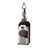
Siemens SIRIUS Operating Instructions Manual (9 pages)
Cable-operated switch with/without latching
Brand:
Siemens
| Category:
Switch
| Size: 11.2 MB
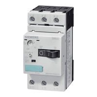
Siemens SIRIUS Operating Instructions Manual (8 pages)
Brand:
Siemens
| Category:
Circuit breakers
| Size: 0.99 MB
Siemens SIRIUS Operating Instructions (2 pages)
Mechanical Interlock for Reversing Contactor
Brand:
Siemens
| Category:
Circuit breakers
| Size: 0.77 MB
Advertisement
Related Products
Siemens SIROTEC
Siemens SIRIUS PROFINET
Siemens SIMATIC HMI
Siemens SIMOTION SCOUT
Siemens SIMODRIVE
Siemens SINAMICS CU240S PN-F
Siemens SINUMERIK Series
Siemens SIMOCODE pro V PB
Siemens SIMATIC PRO Extension Unit 12" Hardwired
Siemens SIMATIC PRO Extension Unit 12" PN Advanced
Siemens Categories
Industrial Equipment
Controller
Control Unit
Oven
Washer
More Siemens Manuals
Login
Sign In
OR
Sign in with Facebook
Sign in with Google
Upload manual
Upload from disk
Upload from URL