Sign In
Upload
Manuals
Brands
Siemens Manuals
Measuring Instruments
SITRANS FUH1010
Siemens SITRANS FUH1010 Manuals
Manuals and User Guides for Siemens SITRANS FUH1010. We have
3
Siemens SITRANS FUH1010 manuals available for free PDF download: Product Instruction Manual, Quick Start Manual
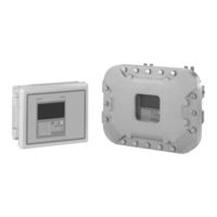
Siemens SITRANS FUH1010 Product Instruction Manual (264 pages)
LIQUID ULTRASONIC FLOWMETER / INTERFACE DETECTOR (IFD)
Brand:
Siemens
| Category:
Measuring Instruments
| Size: 18.18 MB
Table of Contents
Table of Contents
4
1 Introduction
10
Items Supplied
10
History
10
Further Information
11
2 Safety Notes
12
Warning Symbols
12
Laws and Directives
13
Lithium Batteries
14
Installation in Hazardous Area
14
Safety Notes
17
Certificates
21
3 Description
22
FUH1010 Features
22
NEMA 4X & NEMA 7 Transmitters
22
Figure 3-1 Typical Transmitter Label
23
Figure 3-2 NEMA 4X Transmitter Case
23
Applications
24
Figure 3-3 NEMA 7 Transmitter Enclosure with Graphic Display and Keypad
24
Theory of Operation
25
4 Installing/Mounting
32
Installation Safety Precautions
32
Determining a Location
32
Application Guidelines
33
Mounting the Transmitter
33
Figure 4-1 Pipe Mounting and Mounting Locations for Transmitter
34
5 Connecting
36
Safety Notes for Connecting
36
Transmitter Wiring
38
Connecting Power
38
Figure 5-1 Input Power (J10) Wiring
39
Wiring Temperature Sensor to Transmitter
40
Figure 5-2 Analog Input Module Access
41
Figure 5-3 Single Channel Temperature Sensor Inputs
42
Sensor Wiring
44
Wiring the Sensors
44
Figure 5-4 Sensor Cable Connections
45
Navigating the Menu
46
Figure 5-5 Software Version (XX.XX.XX)
46
Figure 5-6 Keypad
46
Programming the Transmitter
47
Table 5- 1 Keypad Function Chart
47
Figure 5-10 Sensor Installation
50
Sensor Installation
51
Preliminary Installation Procedures
51
Figure 5-7 Pipe Surface Preparation
52
Sensor Identification and Selection
53
Figure 5-8 Universal Sensor Label
54
Figure 5-9 Hi Precision Sensor Label
55
Reflect Mount
57
Direct Mount
59
Figure 5-11 Sensor
59
Figure 5-12 Mylar Spacing Guide
60
Figure 5-13 Wrap Strap under Pipe and Attach to Adjusting Screw
61
Figure 5-14 Wrapping the Mylar Spacing Guide Around the Pipe (End View)
62
Figure 5-15 Finding the Halfway Distance
63
1012T Mounting Tracks
64
Figure 5-17 Reflect Mount with Model 1012TN Mounting Track (Side View)
66
Figure 5-18 Direct Mount 180° Opposed with Mounting Tracks
68
Figure 5-19 Track Rail Alignment
70
Figure 5-20 REF and Number Index Pin Locations
71
Mounting Temperature Sensors
72
Table 5- 2 Temperature Sensors
72
6 Commissioning
74
General Requirements
74
Empty Pipe Set
76
Installation Menus
79
7 Functions
84
Setting Liquid Parameters
84
Table 7- 1 Common Liquid Classes
87
Table 7- 2 Liquid Table Data
87
Selecting Flow Units
90
Table 7- 3 Totalizer Modes
91
Table 7- 4 Totalizer Controls (the "N" in <Fn> = Channel Number)
94
Span Data
95
Table 7- 5 Input/Output Wiring (TB2) - 7ME39400AL03 Expanded I/O Module
97
Table 7- 6 Open Collector User Resistor Recommendations
98
Analog out Setup
100
Table 7- 7 Analog Outputs
100
Table 7- 8 Analog out Setup Data Categories
100
Analog Input Setup
102
Table 7- 9 I/O Data Control Menu
102
Expanded I/O Option
105
Table 7- 10 Typical 2-Channel Flow Meter Expanded I/O Option Connections
107
Logger Control
109
Table 7- 11 Logger Control Menu Option List
109
Setting Thermal Coefficient and Modulus of Elasticity
112
Operation Adjust Menu Settings
114
Setting Relays
116
Table 7- 12 Relay Option List
117
Memory Control
119
Table 7- 13 Memory Control Menu
119
Analog Output Trim
120
Table 7- 14 Analog out Trim Menu Structure
120
Resistive Temperature Device (RTD) Calibration
123
Table 7- 15 RTD Calibrate Menu Structure
123
SONILOCATOR Operation
126
8 Alarm, Error and System Messages
130
Alarm Codes
130
Alarms
131
9 Service and Maintenance
134
Maintenance
134
Technical Support
134
Transportation and Storage
135
Repair
136
Unit Repair
136
Return and Disposal
137
Return Procedures (Incl Lithium Batteries)
137
Battery Disposal
138
Disposal
139
10 Troubleshooting
140
F4 Reset Procedure
142
Test Facilities Graph Screen
143
Figure 10-2 Setting Digital Damping Factor
147
Figure 10-3 Setting the Mindamp Factor
148
Table 10- 2 Description of Graph Screen Text Display Parameters
151
Table 10- 3 Hot Key Summary
152
Site Setup Data
153
Force Transmit
158
11 Technical Data
162
A Appendix A
164
A.1 Ordering
164
I/O Connections and Wiring
164
Ordering
164
Figure A-1 7ME39400AL00 and 7ME39400AL01 I/O Module
165
Table A- 2 Input/Output Wiring (TB2) - 7ME39400AL00 and 7ME39400AL01 I/O Module
166
Table A- 3 Input/Output Wiring (TB3) - 7ME39400AL00 and 7ME39400AL01 I/O Module
167
Figure A-2 7ME39400AL03 and 7ME39400AL04 Expanded I/O Module
169
Table A- 5 Input/Output Wiring (TB2) - 7ME39400AL03 and 7ME39400AL04 Expanded I/O Module
170
Table A- 6 Input/Output Wiring (TB3) - 7ME39400AL03 and 7ME39400AL04 Expanded I/O Module
171
Table A- 7 Input/Output Wiring (TB4) - 7ME39400AL03 and 7ME39400AL04 Expanded I/O Module
172
Figure A-3 7ME39400AL04 Expanded I/O Module
174
Table A- 9 Input/Output Wiring (TB2) - 7ME39400AL04 Expanded I/O Module
175
Table A- 10 Open Collector User Resistor Recommendations
176
Table A- 12 Input/Output Wiring (TB4) - 7ME39400AL04 Expanded I/O Module
177
A.3 RS-232 Connection
178
RS-232 Connection
178
Flowrate Calibration and Calibration Tables
187
B Appendix B
192
Installation/Outline Drawings
192
Glossary
194
Index
260
Advertisement
Siemens SITRANS FUH1010 Quick Start Manual (224 pages)
IP65 NEMA 7 Interface Detector
Brand:
Siemens
| Category:
Measuring Instruments
| Size: 12.74 MB
Table of Contents
English
5
Table of Contents
5
Introduction
7
Items Supplied
7
Safety Notes
8
Installation
15
Application Guidelines
15
Mounting the Transmitter
15
Commissioning
19
Connecting Power
19
RS-232 Connection
21
Navigating the Menu
24
Programming the Transmitter
25
General Information
34
Sensor Installation
34
Installing the Sensors (Reflect Mount)
35
Final Setup
38
Troubleshooting
41
Alarm Letter Codes
44
Appendix
45
I/O Connections and Wiring
45
Technical Data
50
Deutsch
57
Einleitung
59
Lieferumfang
59
Sicherheitshinweise
59
Einbau
67
Montage des Messumformers
67
Wichtige Hinweise zur Anwendung
67
Anschließen an die Netzspannung
71
Inbetriebnahme
71
RS-232-Anschluss
74
Navigation IM Menü
77
Programmieren des Messumformers
79
Allgemeine Informationen
88
Messaufnehmer-Installation
88
Installation der Messaufnehmer (Reflekt-Montage)
89
Abschluss der Installation
94
Fehlerbehebung
95
Fehlerbehebung
97
Alarmbuchstabencodes
99
Anhang
101
E/A-Anschlüsse und -Verdrahtung
101
Tabelle
101
Tabelle A- 1 Teilenummern und Anschlusspläne
101
Tabelle A- 2 FUS1010X Eingangs-/Ausgangsverdrahtung (TB1)
102
Tabelle A- 3 FUS1010X Eingangs-/Ausgangsverdrahtung (TB2)
103
Tabelle A- 4 Teilenummern und Anschlusspläne
104
Français
113
Eléments Fournis
115
Introduction
115
Notes Relatives à la Sécurité
115
Installation
123
Instructions à Suivre
123
Montage du Transmetteur
123
Figure 2-1 Montage de Conduite et Emplacements du Support de Montage
124
Mise en Service
127
Raccordement de L'alimentation
127
Figure 3-1 Câblage du Connecteur D'alimentation (P8)
129
Figure 3-2 Ecran du Menu de Programmation du Port Série
130
Figure 3-3 Câblage du Câble D'interface RS-232
132
Navigation Dans le Menu
133
Figure 3-4 Pointe Magnétique et Écran LCD
134
Programmation du Transmetteur
135
Figure 3-5 Etiquette de Capteur Universel
141
Figure 3-6 Etiquette de Capteur Haute Précision
142
Informations Générales
144
Installation des Capteurs
144
Installation des Capteurs (Montage Réflexion)
144
Figure 3-7 Montage Réflexion Avec Châssis de Montage et Entretoise
145
Figure 3-8 Capteur
146
Figure 3-9 Installation des Capteurs
147
Figure 3-10 Raccordement des Capteurs au Débitmètre
148
Configuration Finale
149
Diagnostic D'erreurs
151
4.1 Diagnostic D'erreurs
152
Codes D'alarme
155
Annexe
157
Connexions et Câblage des Entrées/Sorties
157
Tableau A- 1 Numéros de Référence et Schémas de Connexion
157
Tableau A- 2 Câblage Entrée/Sorties X FUS1010 (TB1)
158
Tableau A- 3 Câblage Entrée/Sortie X FUS1010 (TB2)
159
Tableau A- 4 Numéros de Référence et Schémas de Connexion
160
Tableau A- 5 Câblage Entrées/Sorties FUS1010DX (TB1)
161
Tableau A- 6 Câblage des Entrées/Sorties FUS1010DX (TB2)
162
Español
169
Elementos Suministrados
171
Indicaciones de Seguridad
171
Introducción
171
Directrices de Aplicación
179
Instalación
179
Montaje del Transmisor
179
Conexión de la Alimentación Eléctrica
183
Puesta en Marcha
183
Conexión RS-232
185
Tabla 3- 1 Códigos de Colores
185
Navegar por el Menú
188
Tabla 3- 2 Diagrama de Funciones del Lector Magnético
189
Programación del Transmisor
190
Tabla 3- 3 Definiciones Referentes a la Lista de Opciones para la Configuración del Tubo
195
Información General
199
Instalación del Sensor
199
Instalación de Los Sensores (Modo "Reflejar")
200
Ajuste Final
204
Localización Averías
205
Localización de Averías
205
Tabla 4- 1 Recomendaciones para Localizar Averías
205
Códigos de Alarma
209
Anexo
211
Conexiones y Cableado de E/S
211
Números de Piezas y Esquemas de Conexiones
211
Tabla a
211
Tabla a
212
Tabla A- 2 Cableado de Entrada/Salida (TB1) del FUS1010X
212
Cableado de Entrada/Salida (TB2) del FUS1010X
213
Números de Piezas y Esquemas de Conexiones
214
Tabla a
214
Datos Técnicos
216
Índice Alfabético
217
Siemens SITRANS FUH1010 Quick Start Manual (88 pages)
Ultrasonic flowmeters
Brand:
Siemens
| Category:
Measuring Instruments
| Size: 2.32 MB
Table of Contents
Table of Contents
5
Introduction
9
Items Supplied
9
Safety Notes
10
Installing/Mounting
17
Application Guidelines
17
Mounting the Transmitter
17
Connecting
21
Safety Notes for Connecting
21
Transmitter Wiring
23
Wiring Temperature Sensor to Transmitter
27
Navigating the Menu
30
Table 3- 1 Keypad Function Chart
31
Programming the Transmitter
33
Table 3- 2 Pipe Configuration Option List Definitions
36
Sensor Installation
41
General Information
41
Reflect Mount
41
Mounting Temperature Sensors
45
Table 3- 3 Temperature Sensors
45
Sensor Wiring
47
Commissioning
49
Troubleshooting
51
Alarm Codes
53
Appendix
55
I/O Connections and Wiring
55
Technical Data
74
Advertisement
Advertisement
Related Products
Siemens SITRANS FUH1010PVDX
Siemens SITRANS FUH1010PVX
Siemens FUH1010 IP65 NEMA 7 Compact
Siemens Sitrans FUG1010
Siemens SITRANS FUP1010
Siemens SITRANS FUS380
Siemens SITRANS FUE380
Siemens FUS1010
Siemens FUS1010 IP65 NEMA 4X
Siemens SITRANS FUT1010 IP65 NEMA 4X
Siemens Categories
Industrial Equipment
Controller
Control Unit
Oven
Washer
More Siemens Manuals
Login
Sign In
OR
Sign in with Facebook
Sign in with Google
Upload manual
Upload from disk
Upload from URL