Sign In
Upload
Manuals
Brands
Toro Manuals
Paint Sprayer
Multi Pro 5800
Toro Multi Pro 5800 Manuals
Manuals and User Guides for Toro Multi Pro 5800. We have
5
Toro Multi Pro 5800 manuals available for free PDF download: Service Manual, Operator's Manual
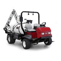
Toro Multi Pro 5800 Service Manual (501 pages)
Brand:
Toro
| Category:
Paint Sprayer
| Size: 15.77 MB
Table of Contents
This Page Is Intentionally Blank.
3
Table of Contents
3
Safety Instructions
6
Before Operating
6
While Operating
7
Maintenance and Service
8
Jacking Instructions
8
Jacking Instructions
9
Safety and Instruction Decals
9
Chapter 2 Product Records and Maintenance
11
Equivalents and Conversions
12
Product Records
12
Torque Specifications
13
Fastener Identification
13
Using a Torque Wrench with an Offset Wrench
13
Standard Torque for Dry, Zinc Plated and Steel Fasteners (Inch Series Fasteners)
14
Standard Torque for Dry, Zinc Plated and
15
Other Torque Specifications
16
Conversion Factors
16
Chapter 3 Kubota Diesel Engine
17
Chapter 4 − Kubota Gasoline Engine
17
General Information
17
Specifications
18
General Information
19
Operator's Manual
19
Kubota Workshop Manual
19
Chapter 6 − Electrical System
19
Adjustments
19
Adjustments
20
Adjust Throttle Cable
20
Service and Repairs
22
Fuel System
22
Air Cleaner
24
Exhaust System
26
Radiator
28
Removal
28
Installation
30
Flywheel Coupler
38
Chapter 4 Kubota Gasoline Engine
41
Chapter 7 − Excelarate Spray System
41
Troubleshooting
41
Specifications
42
General Information
43
Operator's Manual
43
Kubota Workshop and Troubleshooting Manuals
43
Kubota Gasoline Engine
43
Kubota Gasoline Engine Electronic Control Module (ECM)
44
Service and Repairs
46
Fuel System
46
Air Cleaner
50
Exhaust System
52
Radiator
54
Engine
58
Engine Removal
59
Flywheel Coupler
62
Chapter 5 Hydraulic System
65
Specifications
67
General Information
68
Operator's Manual
68
Traction Circuit Component Failure
68
Hydraulic Hoses
69
Hydraulic Hose and Tube Installation
70
Hydraulic Fitting Installation
71
Hydraulic Schematic
73
Hydraulic Flow Circuits
74
Traction Circuit
75
Steering Circuit
77
Spray Pump Drive Circuit
79
Spray Boom Lift Circuit
81
Special Tools
82
Troubleshooting
86
Testing
90
Adjustments
91
Traction Circuit Charge Pressure Test
92
Charge Pump Flow Test
94
Wheel Motor Efficiency Test
96
Hydraulic System
96
Traction (Piston) Pump Flow and Relief Pressure Test
100
Steering/Boom Lift Circuit
104
Steering Control Valve and Steering Cylinder Test
108
Chapter 8 − Geolink Spray System
91
Chapter 1 − Safety
109
Chapter 2 − Product Records and Maintenance
109
Chapter 3 − Kubota Diesel Engine
109
Service and Repairs
109
Boom Lift Cylinder Internal Leakage Test
110
Spray Pump Circuit Gear Pump P1 Flow Test (Using Tester with Flow Meter and Pressure Gauge)
112
Adjustments
114
Adjust Traction Pedal for Neutral
114
Service and Repairs
115
General Precautions for Removing and Installing Hydraulic System Components
115
Check Hydraulic Lines and Hoses
115
Priming Hydraulic Pumps
116
Flush Hydraulic System
117
Filtering Closed- Loop Traction Circuit
118
Charging Hydraulic System
119
Gear Pump
120
Gear Pump Service
122
Piston (Traction) Pump
128
Wheel Motors
132
Wheel Motor Service
134
Spray Pump Drive Motor and Control Manifold Assembly
136
Spray Pump Drive Motor Service
138
Spray Pump Control Manifold Service
140
Steering Control Valve
142
Steering Control Valve Service
144
Steering Cylinder
146
Steering Cylinder Service
148
Boom Lift Manifold
150
Boom Lift Manifold Service
152
Boom Lift Cylinders
154
Boom Lift Cylinder Service
156
Oil Cooler
158
Hydraulic Reservoir
160
Chapter 6 Electrical System
163
General Information
164
Operator's Manual
164
Toro Electronic Controller (TEC)
164
Kubota Gasoline Engine
165
CAN- Bus Communications
165
Electrical Drawings
166
Special Tools
167
Infocenter Display
171
Infocenter Display Screens Excelarate Spray System
172
Infocenter Display Screens Geolink Spray System
173
Splash Screen
174
Operator's Information
175
Spray Areas
176
Main Menu
177
Set Rates
178
Settings
179
Calibration
183
Service
184
Diagnostics
186
About
191
Troubleshooting
192
Starting Problems
192
Operator Advisories
195
Machine Faults
199
Engine Faults (Gasoline Engines Only)
200
Electrical System Quick Checks
201
Battery Test (Open Circuit Test)
201
Charging System Test
201
Glow Plug System Test
201
Check Operation of Interlock Switches
202
Adjustments
203
Brake Pedal Switch
203
Component Testing
204
Fusible Links
205
Service and Repairs
205
Fuses (Gasoline Engines Only)
206
Engine Fuses
208
Toro Electronic Controller (TEC)
209
Ignition Switch
211
Indicator Lights (Diesel Engines Only)
212
Headlight Switch (Standard)
213
Spray Mode Switch (Excelarate Spray Systems Only)
214
Speed Lock Switch
215
Application Rate Switch
216
Boom Lift Switches
217
Spray Pump Enable and Agitation Switches
218
Master Boom (Spray Enable) Switch
219
Boom Control Switches
220
Speed Lock Coil
221
Brake Pedal Switch
222
Relays with Four (4) Terminals
223
Relays with Five (5) Terminals
224
Engine Relays (Gasoline Engines Only)
225
Traction Speed Sensor
227
Hydraulic Valve Solenoid Coils
228
Neutral Switch
229
Glow Plug Controller (Diesel Engines Only)
231
Fuel Pump (Gasoline Engines Only)
232
Fuel Pump (Diesel Engines Only)
234
Fuel Level Sender (Gasoline Engines Only)
235
Coolant Temperature Sender
238
Oil Pressure Switch
239
CAN- Bus Terminator Resistors
240
Diode Assemblies
241
Resistor Assemblies
242
Spray System Valve Actuators
243
Operator Seat Switch
244
Audible Alarm
245
Throttle Assembly (Gasoline Engines Only)
246
Flow Meter Sensor
247
Pressure Transducer
248
Horn Button (Optional)
249
Tank Clean Rinse Pump Switch (Optional)
250
Foam Marker ON/OFF Switch (Optional)
251
Foam Marker Control Switch (Optional)
252
Electric Hose Reel Motor Switch (Optional)
253
Electric Hose Reel Rate Switch (Optional)
254
Road Headlight Switch (Optional)
255
Hazard Light Switch (Optional)
256
Service and Repairs
257
Headlights
257
Traction Speed Sensor
258
Flow Meter Sensor
259
Speed Lock Coil
260
Battery Storage
261
Battery Care
261
Battery Service
262
Chapter 7 Excelarate Spray System
265
Specifications
266
General Information
267
User Manuals
267
Precautions Concerning Chemicals Used in Spray System
267
Precautions for Removing or Adjusting Spray System Components
267
Special Tools
268
Excelarate Spray System Diagram
270
Excelarate Spray System Operation
271
Infocenter Display
273
Infocenter Display Screens
274
Splash Screen
275
Operator's Information
276
Spray Areas
277
Main Menu
278
Set Rates
279
Settings
280
Calibration
282
Service
283
Diagnostics
285
About
289
Troubleshooting
290
Spray System Problems
290
Operator Advisories
292
Using the Infocenter Display for Troubleshooting
293
Machine Faults
294
Service and Repairs
295
Spray Pump
295
Spray System Components
295
Spray Pump Service
299
Pressure Relief Valve
303
Spray Control Manifold Assembly
304
Agitation Valve Assembly
306
Boom Section Valve Assembly
307
Boom Section Valve and Agitation Valve Service
308
Agitation Bypass Valve Service
309
Boom Section Bypass Valve Service
310
Boom Section Bypass Shut−Off Valve and Agitation Throttle Valve Service
311
Flow Meter
312
Flow Meter Service
314
Suction Line
316
Agitation Line
318
Drain Line
320
Turret Bodies
322
Turret Body Service
324
Boom Hinge
326
Spray Tank
328
Chapter 8 Geolink Spray System
331
Specifications
332
General Information
333
User Manuals
333
Geolink Spray System Service and Support
333
Precautions Concerning Chemicals Used in Spray System
333
Precautions for Removing or Adjusting Spray System Components
333
Geolink Terminology
334
Special Tools
335
Geolink Spray System Diagram
336
Geolink Spray System Operation
337
Geolink Components
338
X25 and X30 Control Console Screens
341
Operation Screen
341
Setup Screen
353
Infocenter Display
357
Splash Screen
359
Operator's Information
360
Main Menu
361
Settings
362
Service
363
Diagnostics
364
About
368
Troubleshooting
369
Automatic Section Control Override
369
Remote Assistance (X30 Consoles Only)
370
X25 or X30 Control Console Error Messages
371
Crash Reports
371
Guidance and Rate Management System
372
Operator Advisories (Infocenter Display)
373
Using the Infocenter Display for Troubleshooting
374
Machine Fault (Infocenter Display)
375
Product Handling System
376
Adjustments
378
Compass Calibration
378
Flow Meter Calibration
379
Service and Repairs
381
GPS Antenna (AGI−4)
381
Modem (Machines with RTK Correction)
382
Inertial Measurement Unit (IMU) (Machines with RTK Correction)
383
X25 or X30 Control Console
386
Can−Bus Terminator Resistors
388
Fuses
388
Material Handling "Wet" Components
389
Spray Pump
389
Spray Pump Service
394
Pressure Relief Valve
398
Spray Control Manifold Assembly
400
Agitation Valve Assembly
402
Nozzle Valve Assembly
404
Nozzle Valve and Agitation Valve Service
406
Agitation Bypass Valve Service
407
Agitation Throttle Valve Service
408
Flow Meter
409
Flow Meter Service
410
Suction Line
412
Agitation Line
414
Drain Line
416
Turret Body Service
420
Spray Boom Hinge
422
Spray Tank
424
Chapter 9 Chassis
427
General Information
428
Operator's Manual
428
Wheel Assemblies
430
Tie Rod
431
Front Wheel Hubs
432
Front Spindles
434
Front Suspension
436
Planetary Drive Assembly
438
Planetary Drive Service
440
Brake Cables
443
Brake Assembly
444
Brake Inspection and Repair
447
Console Assembly
450
Specifications
428
Chapter 10 Ultra Sonic Boom Kit (Optional)
453
General Information
454
Installation Instructions
454
Parts Catalog
454
System Configuration
454
Can−Bus Communications
455
Precautions Concerning Chemicals Used in Spray System
455
Precautions for Removing or Adjusting Spray System Components
455
Hydraulic Schematic
456
Electrical Schematic
457
Ultra Sonic Boom System Operation
458
Sprayer Operation on Level Turf
459
Rise in Turf Encountered
463
Boom Level Changed by Operator During Automatic Operation
465
Manual Boom Operation
467
Troubleshooting
468
Ultra Sonic Boom Calibration
468
Ultra Sonic Boom Light
468
Troubleshooting Chart
469
Ultra Sonic Boom Fuses
471
Service and Repairs
471
Ultra Sonic Boom Switch
472
Sonic Sensors
473
Toro Electronic Controller (TEC)
475
Wire Harness Drawings
475
Can−Bus Termination Resistors
476
Ultra Sonic Boom Lift Manifold Service
478
Electrical Drawing Designations
482
Wire Color
482
Wire Size
482
Hydraulic Schematic
483
Multi Pro 5800- D
484
Multi Pro 5800- G
486
Geolink Spray System (Optional)
488
Ultra Sonic Boom Kit (Optional)
489
Wire Harness Drawings
500
Ultra Sonic Boom Kit (Optional) Wire Harness
500
Advertisement
Toro Multi Pro 5800 Service Manual (294 pages)
Brand:
Toro
| Category:
Paint Sprayer
| Size: 20.88 MB
Table of Contents
Safety
11
Table of Contents
11
Before Operating
12
Chapter 1
12
Safety Instructions
12
While Operating
12
Maintenance and Service
13
Jacking Instructions
14
Safety and Instruction Decals
14
Product Records and Maintenance
15
Chapter 2
16
Equivalents and Conversions
16
Product Records
16
Torque Specifications
17
Fastener Identification
17
Using a Torque Wrench with an Offset Wrench
17
Standard Torque for Dry, Zinc Plated and Steel Fasteners (Inch Series Fasteners)
18
Standard Torque for Dry, Zinc Plated and Steel Fasteners (Metric Fasteners)
19
Other Torque Specifications
20
Conversion Factors
20
Kubota Diesel Engine
21
Chapter 3
22
Specifications
22
Adjustments
23
Fuel System
24
Air Cleaner
26
Exhaust System
28
Radiator
30
Engine
32
Engine Removal
33
Engine Installation
34
Flywheel Coupler
36
Hydraulic System
39
Specifications
41
General Information
42
Operator's Manual
42
Check Hydraulic Fluid
42
Towing Sprayer
42
Traction Circuit Component Failure
43
Hydraulic Hoses
44
Hydraulic Hose and Tube Installation
45
Hydraulic Fitting Installation
46
Hydraulic Schematic
48
Hydraulic Flow Circuits
50
Traction Circuit
51
Steering Circuit
53
Spray Pump Drive Circuit
55
Spray Boom Lift Circuit
57
Special Tools
58
Troubleshooting
62
Testing
66
Traction Circuit Charge Pressure Test
68
Traction Circuit Relief Pressure Test
70
Wheel Motor Efficiency
72
Charge Pump Flow Test
76
Piston (Traction) Pump Flow Test
78
Steering/Boom Lift Circuits Relief Pressure Test
80
Steering/Boom Lift Circuits Gear Pump Flow Test
82
Steering Cylinder Internal Leakage Test
84
Boom Lift Cylinder Internal Leakage Test
86
Spray Pump Circuit Gear Pump Flow Test
88
Adjustments
90
Adjust Traction Pedal for Neutral
90
Chapter 4
91
General Precautions for Removing and Installing Hydraulic System Components
91
Service and Repairs
91
Check Hydraulic Lines and Hoses
92
Flush Hydraulic System
93
Filtering Closed--Loop Traction Circuit
94
Charge Hydraulic System
95
Gear Pump
96
Gear Pump Service
98
Piston (Traction) Pump
100
Piston (Traction) Pump Service
104
Wheel Motors
106
Wheel Motor Service
108
Spray Pump Drive Motor
110
Spray Pump Drive Motor Service
114
Steering Control Valve
120
Steering Control Valve Service
122
Steering Cylinder
124
Steering Cylinder Service
126
Boom Lift Control Manifold
128
Boom Lift Control Manifold Service
130
Boom Lift Cylinder
132
Boom Lift Cylinder Service
134
Oil Cooler
136
Hydraulic Reservoir
138
Electrical System
141
General Information
142
Electrical Drawings
142
Operator's Manual
142
Special Tools
143
Troubleshooting
144
Starting Problems
144
General Run Problems
145
Electrical System Quick Checks
146
Battery Test (Open Circuit Test)
146
Charging System Test
146
Glow Plug System Test
146
Neutral Switch Operation
147
Component Testing
148
Ignition Switch
148
Indicator Lights
149
Hour Meter
150
Headlight Switch
151
Speed Lock Switch
152
Pressure Rate Switch
153
Boom Lift Switches
154
Spray Pump, Agitation and Boom Control Switches
155
Chapter 5
156
Master Boom (Foot) Switch
156
Speed Lock Coil
157
Brake Pedal Switch
158
Spray System Relays
159
Main, Glow and Speed Lock Relays
160
Traction Speed Sensor
161
Hydraulic Valve Solenoid Coils
162
Manual Interface Module
163
Neutral Switch
164
Fuel Stop Solenoid
165
Glow Plug Controller
166
Fuel Pump
167
Temperature Sender
168
Fusible Links
169
Diode Assemblies
170
Headlights
171
Service and Repairs
171
Traction Speed Sensor
172
Speed Lock Coil
173
Battery Care
174
Battery Storage
174
Battery Service
175
Spray System
179
Specifications
180
General Information
181
Operator's Manual
181
Precautions Concerning Chemicals Used in Spray System
181
Precautions for Removing or Adjusting Spray System Components
181
Spray System Flow Diagram
182
Spray System Operation
183
Troubleshooting
184
Service and Repairs
186
Spray Pump
186
Spray Pump Service
190
Agitation Supply
194
Chapter 6
194
Pressure Relief Valve
196
Spray Control Assembly
198
Boom Manifold Valve Assembly
200
Agitation Valve Assembly
202
Boom and Agitation Valve Motor Service
204
Tank Suction
206
Tank Drain Valve
208
Turret Bodies
210
Turret Body Service
212
Boom Hinge
214
Pro Control XP Spray System (Optional)
216
Chassis
217
Specifications
218
Chapter 7 Operator's Manual
219
General Information
219
Adjustments
220
Planetary Drive Assembly Endplay
220
Service and Repairs
221
Tie Rod Ends
221
Front Wheels and Hubs
222
Spindles
224
Front Suspension
226
Brake Assembly
228
Brake Inspection and Repair
232
Brake Cables
233
Planetary Drive Assembly
234
OPH−2 Series Planetary Drive Service
236
VH02 Series Planetary Drive Service
240
Console Assembly
244
.1 Ultra Sonic Boom System (Optional Kit)
247
General Information
248
Installation Instructions
248
Precautions Concerning Chemicals Used in Spray System
248
Precautions for Removing or Adjusting Spray System Components
248
Special Tools
249
Hydraulic Schematic
250
Electrical Schematic
251
Ultra Sonic Boom System Operation
252
Sprayer Operation on Level Turf
253
Downward Slope in Turf Encountered
255
Rise in Turf Encountered
257
Boom Level Changed by Operator During Automatic Operation
259
Manual Boom Operation
261
Troubleshooting
263
Sonic Boom Light
263
Sonic Boom Calibration
263
Diagnostic Lamp
264
Diagnostic Display
266
Troubleshooting Chart
270
Service and Repairs
272
Fuses
272
Sonic Boom Switch
273
Sonic Sensors
274
Toro Electronic Controller (TEC)
276
Boom Lift Control Manifold
283
Hydraulic Schematic
283
Chapter 8
284
Vehicle Electrical Schematic
284
Spray System Electrical Schematic
285
Glow Plug Circuit
286
Start Circuit
287
Run Circuit
288
Speed Lock Circuit
289
Front Wire Harness
290
Rear Wire Harness
292
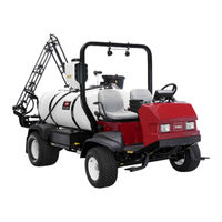
Toro Multi Pro 5800 Operator's Manual (64 pages)
Turf Sprayer
Brand:
Toro
| Category:
Farm Equipment
| Size: 2.2 MB
Table of Contents
Table of Contents
2
Safety
4
Safe Operating Practices
4
Chemical Safety
4
Before Operating
5
While Operating
5
Maintenance
7
Sound Power
7
Sound Pressure
7
Hand-Arm Vibration
7
Whole Body Vibration
7
Safety and Instructional Decals
8
1 Checking the Boom Hinge Springs
12
Setup
12
2 Learning more about Your Product
13
Product Overview
14
Controls
15
Specifications
20
Operation
20
Think Safety First
20
Before Driving the Sprayer for the First Time
20
Pre-Starting Checks
22
Driving the Sprayer
22
New Sprayer Break-In
23
Operating the Sprayer
23
Filling the Fresh Water Tank
24
Filling the Spray Tank
24
Operating the Booms
24
Spraying
25
Turf Care Precautions While Operating in Stationary Modes
25
Spraying Tips
25
Unclogging a Nozzle
26
Selecting a Nozzle
26
Cleaning the Sprayer
26
Calibrating the Agitation Bypass Valve
27
Pump
28
Transporting the Sprayer
28
Towing the Sprayer
28
Maintenance
30
Recommended Maintenance Schedule(S)
30
Daily Maintenance Checklist
31
Notation for Areas of Concern
33
Pre-Maintenance Procedures
33
Jacking the Sprayer
33
Lubrication
34
Greasing the Sprayer
34
Greasing the Boom Hinges
34
Greasing the Actuator Rod Bearings
35
Engine Maintenance
36
Servicing the Air Cleaner
36
Servicing the Engine Oil
37
Fuel System Maintenance
39
Checking the Fuel Line and Connections
39
Bleeding the Fuel System
39
Bleeding Air from the Injectors
40
Draining the Fuel Tank
40
Servicing the Fuel Filters
41
Electrical System Maintenance
42
Replacing the Fuses
42
Servicing the Battery
42
Drive System Maintenance
44
Check the Tire Pressure
44
Inspecting the Wheels/Tires
44
Changing the Planetary Gearbox Fluid
44
Adjusting the Front Wheel Toe-In
45
Cooling System Maintenance
46
Checking the Coolant Level
46
Servicing the Cooling System
46
Brake Maintenance
48
Checking the Brakes
48
Adjusting the Brakes
48
Belt Maintenance
49
Servicing the Drive Belts
49
Hydraulic System Maintenance
49
Hydraulic Fluid Specification
49
Checking the Hydraulic Fluid
50
Servicing the Hydraulic Oil
50
Spray System Maintenance
52
Inspecting the Hoses
52
Pump Maintenance
53
Adjusting the Actuators
53
Inspecting the Nylon Pivot Bushings
54
Inspecting the Tank Straps
54
Cleaning
55
Cleaning the Suction Strainer
55
Storage
56
Troubleshooting
57
Schematics
60
Advertisement
Toro Multi Pro 5800 Operator's Manual (36 pages)
Turf Sprayer with ExcelaRate Spray System
Brand:
Toro
| Category:
Paint Sprayer
| Size: 5.07 MB
Table of Contents
Table of Contents
1
Introduction
1
Setup
1
Before You Begin Spraying
1
Product Overview
2
Controls
2
Operation
3
Before Operation
3
Accessing the Main Menu Screen
3
Infocenter Main Sub Menus
4
Calibrating the Sprayer
14
During Operation
26
Infocenter Spray Area Screens
26
Infocenter Advisories
28
Infocenter Fault Codes
29
Maintenance
30
Service Screens
30
Diagnostics Screens
31
About Screens
32
Toro Multi Pro 5800 Operator's Manual (20 pages)
Turf Sprayer, Precision Spray System
Brand:
Toro
| Category:
Paint Sprayer
| Size: 14.63 MB
Table of Contents
Table of Contents
2
Safety
3
Product Overview
4
Controls
4
Operation
6
Understanding the Different Display Modes
6
Starting the Display
6
Understanding the LED Lights
6
Using the Touch Screen
7
Using the Master Switch
7
Selecting the Correct Units of Measure
7
Using the Easy Mode
8
Recording Job Details
11
Exporting Job Information
12
Setting up the System
13
Initially Testing the System
13
Operating Tips
14
Maintenance
15
Recommended Maintenance Schedule(S)
15
Cleaning the Flowmeter
15
Cleaning the Display Screen
15
Troubleshooting
16
Advertisement
Related Products
Toro Multi Pro 5500
Toro Multi Pro 5800-G
Toro Multi Pro 5800-D
Toro MULTI PRO 5600
Toro Multi Pro 1200
Toro Multi Pro 41188
Toro Multi Pro 41394
Toro Multi Pro 315000001
Toro Multi Pro 41240
Toro Multi Pro 41118
Toro Categories
Lawn Mower
Lawn Mower Accessories
Snow Blower
Lawn and Garden Equipment
Utility Vehicle
More Toro Manuals
Login
Sign In
OR
Sign in with Facebook
Sign in with Google
Upload manual
Upload from disk
Upload from URL