Sign In
Upload
Manuals
Brands
Toshiba Manuals
Laptop
EQUIUM L300D
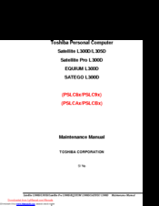
Toshiba EQUIUM L300D Manuals
Manuals and User Guides for Toshiba EQUIUM L300D. We have
2
Toshiba EQUIUM L300D manuals available for free PDF download: Maintenance Manual
Toshiba EQUIUM L300D Maintenance Manual (244 pages)
Maintenance Manual
Brand:
Toshiba
| Category:
Laptop
| Size: 13.83 MB
Table of Contents
Table of Contents
7
Hardware Overview
4
Troubleshooting
4
Table of Contents
15
Features
17
Figure 1-1 ID Parts Description Placement
21
Figure 1-2 Computer Block Diagram
22
Figure 1-3 System Board Configurations
23
Figure 1-4 System Unit Block Diagram
24
System Unit Components
24
Figure 1-5 SATA HDD
29
Inch HDD
29
Table 1-1 HDD Specifications
29
Hardware Overview
29
Combo CD-RW/DVD-ROM
30
Figure 1-6 Combo CD-RW/DVD-ROM Drive
30
Table 1-2 Combo CD-RW/DVD-ROM Drive Specifications
30
DVD Super Multi (+-R Double Layer)
31
Table 1-3 DVD Super Multi Drive Specifications
31
Power Supply
32
Batteries
33
Main Battery
33
Battery Charging Control
33
Table 1-4 Battery Specifications
33
RTC Battery
34
Table 1-5 Quick/Normal Charging Time
34
Troubleshooting
36
Outline
39
Basic Flowchart
40
Power Supply
44
Procedure 1 Power Icon Check
44
Procedure 2 Connection Check
44
Procedure 3 Replacement Check
44
System Board
47
Procedure 1 Message Check
47
Procedure 2 Test Program Check
48
Procedure 3 Replacement Check
48
Inch HDD
49
Procedure 1 Message Check
49
Procedure 2 Partition Check
49
Procedure 3 Format Check
49
Procedure 4 Test Program Check
49
Procedure 5 Connector Check and Replacement Check
49
Procedure 4 Test Program Check
51
Procedure 5 Connector Check and Replacement Check
52
Keyboard
53
Procedure 1 Test Program Check
53
Procedure 2 Connector Check and Replacement Check
53
Display
54
Procedure 1 External Monitor Check
54
Procedure 2 Test Program Check
54
Procedure 3 Connector Check and Replacement Check
54
ODD (Optical Disk Drive)
56
Procedure 1 ODD Cleaning Check
56
Procedure 2 Test Program Check
56
Procedure 3 Connector Check and Replacement Check
56
Lan
58
Procedure 1 Test Program Check
58
Procedure 2 Connector Check and Replacement Check
58
Audio Test
59
Procedure 1 Test Program Check
59
Procedure 2 Connector Check and Replacement Check
59
Cooling Module
60
Procedure 1 Test Program Check
60
Procedure 2 Connector Check and Replacement Check
60
Chapter Diagnostic Programs
63
General
66
Quick Start
68
Quick Test
68
Customization Test
68
Keyboard Layout Test
72
Hotkey Test
73
Audio Play Test
73
Audio Record Test
74
DMI Read
74
DMI Write
74
System Information
76
View Logs
77
Exit to )UHH DOS
78
The Diagnostics Screen Explanation
78
Options
81
Overview
81
Batch Parameters Configuration
82
Item's Parameters Configuration
84
Load Batch Parameters
85
Save Batch Parameters
86
LOG Parameters Setting
87
Specify LOG Viewer
88
Display LOG File
88
LOG Viewer
89
LOG File Sample
90
Subtests
92
System Test
95
Memory Test
100
Storage
106
Video
110
Communication (COMM)
120
Peripheral
121
Error Codes and Description
123
Quick Test Item List
128
Table of Contents
131
General
136
Safety Precautions
137
Before You Begin
139
Disassembly Procedures
140
Assembly Procedures
140
Tools and Equipment
141
Screw Tightening Torque
141
Colors of Screw Shanks
142
Symbols of Screws on the Computer Body
142
Symbol Examples
142
Removing the Battery Pack
143
Installing the Battery Pack
144
Removing the Optional PC Card
145
Installing the Optional PC Card
146
Removing the Momery Card
147
Installing the Momery Card
148
Removing the Optional Memory
149
Installing the Optional Memory
150
Hdd
151
Removing the HDD
151
Installing the HDD
153
ODD Bay Module
154
Removing the ODD Bay Module
154
Installing the ODD Bay Module
155
Keyboard
157
Removing the Keyboard
157
Installing the Keyboard
158
MDC Module
159
Removing the MDC Module
159
Installing the MDC Module
160
Wireless LAN Card
161
Removing the Wireless LAN Card
161
Installing the Wireless LAN Card
162
Top Cover
163
Removing the Top Cover
163
Installing the Top Cover
164
Display Assembly
165
Removing the Display Assembly
165
Installing the Display Assembly
166
System Board
167
Removing the System Board
167
Installing the System Board
168
CPU Cooling Module and Fan
169
Installing the CPU Cooling Module and Fan
172
Cpu
173
Removing the CPU
173
Installing the CPU
174
Display Mask
176
FL Inverter Board
178
Removing the FL Inverter Board
178
Installing the FL Inverter Board
179
Removing the LCD Module
180
Installing the LCD Module
182
CCD Board and MIC
183
Touch Pad and Button Board
186
Appendix A Handling the Lcd Module
193
Appendix B Board Layout
198
B.2 System Board Back View
200
AppendixC
201
CN1 Power Board Connector (4-Pin
201
CN2 Switch Board Connector (12-Pin
201
CN3 AC-In Cable Connector (4-Pin
201
CN4 CRT Cable Connector (14-Pin
201
Appendix C Pin Assignments
201
CN5 LCD/FL Inverter Cable Connector (40-Pin
202
CN6 Modem Module Connector (12-Pin
202
CN10 Internal Speaker Cable Connector (6-Pin
203
CN7 CCD Camera Cable Connector (5-Pin
203
CN8 Touch Pad Board Cable Connector (12-Pin
203
CN11 Wireless LAN Module Connector (52-Pin
204
CN12 Internal Keyboard Cable Connector (34-Pin
205
CN13 Express Card Module Connector (26-Pin
205
CN14 Internal MIC Phone Cable Connector (2-Pin
206
CN15 USB Port2 Board Cable Connector (5-Pin
206
CN16 PCMCIA Slot Module Connector (68-Pin
206
CN17 HDD Connector (22-Pin
207
CN500 Battery Pack Connector (9-Pin
208
CN501 FAN Connector (3-Pin
208
CN502 DDR2 DIMM0 Connector (200-Pin
208
CN503 DDR2 DIMM1 Connector (200-Pin
211
CN505 ODD Connector (50-Pin
214
CN506 USB Port0 & Port1 Connector (8-Pin
215
CN507 HDMI Connector (19-Pin
215
CN508 Bridge Media Slot Connector (21-Pin
216
CN510 Broadcom Decoder Connector (52-Pin
216
JACK500 RJ45 LAN Connector (12-Pin
217
JACK501 External MIC Connector (6-Pin
217
CN4000 USB Port2 Connector (4-Pin
218
CN5000 Touch Pad Module Connector (12-Pin
218
JACK502 Head Phone Connector (6-Pin
218
CN5001 Touch Pad Board Cable Connector (12-Pin
219
Appendix E Key Layout
228
Appendix F Bios Rewrite Procedures
243
Advertisement
Toshiba EQUIUM L300D Maintenance Manual (244 pages)
Brand:
Toshiba
| Category:
Laptop
| Size: 45.01 MB
Table of Contents
Table of Contents
15
Hardware Overview
13
Table of Contents
15
Features
17
Figure 1-1 ID Parts Description Placement
21
Figure 1-2 Computer Block Diagram
22
Figure 1-3 System Board Configurations
23
System Unit Components
24
Figure 1-4 System Unit Block Diagram
24
Inch HDD
29
Figure 1-5 SATA HDD
29
Table 1-1 HDD Specifications
29
Combo CD-RW/DVD-ROM
30
Figure 1-6 Combo CD-RW/DVD-ROM Drive
30
Table 1-2 Combo CD-RW/DVD-ROM Drive Specifications
30
DVD Super Multi (+-R Double Layer)
31
Table 1-3 DVD Super Multi Drive Specifications
31
Power Supply
32
Batteries
33
Main Battery
33
Battery Charging Control
33
Table 1-4 Battery Specifications
33
RTC Battery
34
Table 1-5 Quick/Normal Charging Time
34
Troubleshooting
35
Troubleshooting
36
Outline
39
Basic Flowchart
40
Power Supply
44
Procedure 1 Power Icon Check
44
Procedure 2 Connection Check
44
Procedure 3 Replacement Check
44
System Board
46
Procedure 2 Connection Check
46
Procedure 1 Message Check
47
System Board
47
Procedure 2 Test Program Check
48
Procedure 3 Replacement Check
48
Inch HDD
49
Procedure 1 Message Check
49
Procedure 2 Partition Check
49
Procedure 3 Format Check
49
Procedure 4 Test Program Check
49
Procedure 5 Connector Check and Replacement Check
49
Procedure 3 Format Check
50
Procedure 4 Test Program Check
51
Procedure 5 Connector Check and Replacement Check
52
Keyboard
53
Procedure 1 Test Program Check
53
Procedure 2 Connector Check and Replacement Check
53
Display
54
Procedure 1 External Monitor Check
54
Procedure 2 Test Program Check
54
Procedure 3 Connector Check and Replacement Check
54
ODD (Optical Disk Drive)
56
Procedure 1 ODD Cleaning Check
56
Procedure 2 Test Program Check
56
Procedure 3 Connector Check and Replacement Check
56
Lan
58
Procedure 1 Test Program Check
58
Procedure 2 Connector Check and Replacement Check
58
Audio Test
59
Cooling Module
60
Chapter Diagnostic Programs
63
General
66
Quick Start
68
Quick Test
68
Customization Test
68
Keyboard Layout Test
72
Hotkey Test
73
Audio Play Test
73
Audio Record Test
74
DMI Read
74
DMI Write
74
System Information
76
View Logs
77
Exit to )UHH DOS
78
The Diagnostics Screen Explanation
78
Options
81
Overview
81
Batch Parameters Configuration
82
Item's Parameters Configuration
84
Load Batch Parameters
85
Save Batch Parameters
86
LOG Parameters Setting
87
Specify LOG Viewer
88
Display LOG File
88
LOG Viewer
89
LOG File Sample
90
Subtests
92
System Test
95
Memory Test
100
Storage
106
Video
110
Communication (COMM)
120
Peripheral
121
Led Test
122
Error Codes and Description
123
Quick Test Item List
128
Table of Contents
131
General
136
Safety Precautions
137
Before You Begin
139
Disassembly Procedures
140
Assembly Procedures
140
Tools and Equipment
141
Screw Tightening Torque
141
Colors of Screw Shanks
142
Symbols of Screws on the Computer Body
142
Symbol Examples
142
Removing the Battery Pack
143
Installing the Battery Pack
144
Removing the Optional PC Card
145
Installing the Optional PC Card
146
Removing the Momery Card
147
Installing the Momery Card
148
Removing the Optional Memory
149
Installing the Optional Memory
150
Hdd
151
Removing the HDD
151
Installing the HDD
153
ODD Bay Module
154
Removing the ODD Bay Module
154
Installing the ODD Bay Module
155
Keyboard
157
Removing the Keyboard
157
Replacement Procedures
157
Installing the Keyboard
158
MDC Module
159
Removing the MDC Module
159
Installing the MDC Module
160
Wireless LAN Card
161
Removing the Wireless LAN Card
161
Installing the Wireless LAN Card
162
Top Cover
163
Removing the Top Cover
163
Installing the Top Cover
164
Display Assembly
165
Removing the Display Assembly
165
Installing the Display Assembly
166
System Board
167
Removing the System Board
167
Installing the System Board
168
CPU Cooling Module and Fan
169
Installing the CPU Cooling Module and Fan
172
Cpu
173
Removing the CPU
173
Installing the CPU
174
Display Mask
176
Fl Inverter Board
178
Lcd Module
180
CCD Board and MIC
183
Touch Pad and Button Board
186
Appendix A Handling the Lcd Module
193
Appendix B Board Layout
198
B.2 System Board Back View
200
Pin Assignments
201
AppendixC
202
CN5 LCD/FL Inverter Cable Connector (40-Pin
202
CN6 Modem Module Connector (12-Pin
202
CN10 Internal Speaker Cable Connector (6-Pin
203
CN8 Touch Pad Board Cable Connector (12-Pin
203
CN11 Wireless LAN Module Connector (52-Pin
204
CN17 HDD Connector (22-Pin
207
CN500 Battery Pack Connector (9-Pin
208
CN501 FAN Connector (3-Pin
208
CN502 DDR2 DIMM0 Connector (200-Pin
208
CN503 DDR2 DIMM1 Connector (200-Pin
211
CN505 ODD Connector (50-Pin
214
CN506 USB Port0 & Port1 Connector (8-Pin
215
CN507 HDMI Connector (19-Pin
215
CN508 Bridge Media Slot Connector (21-Pin
216
CN510 Broadcom Decoder Connector (52-Pin
216
JACK500 RJ45 LAN Connector (12-Pin
217
JACK501 External MIC Connector (6-Pin
217
CN4000 USB Port2 Connector (4-Pin
218
CN5000 Touch Pad Module Connector (12-Pin
218
Touch Pad Board
218
JACK502 Head Phone Connector (6-Pin
218
CN5001 Touch Pad Board Cable Connector (12-Pin
219
Appendix E Key Layout
228
Appendix F Bios Rewrite Procedures
243
Advertisement
Related Products
Toshiba EQUIUM L350
Toshiba EQUIUM L350D
Toshiba Equium A60
Toshiba E105-S1402
Toshiba Satellite E105-S1802
Toshiba E305-S1990X
Toshiba Qosmio E15
Toshiba Satellite E205
Toshiba Satellite E305
Toshiba Satelite E200
Toshiba Categories
Laptop
Air Conditioner
TV
LCD TV
All in One Printer
More Toshiba Manuals
Login
Sign In
OR
Sign in with Facebook
Sign in with Google
Upload manual
Upload from disk
Upload from URL