Table of Contents
Advertisement
Advertisement
Table of Contents

Related Manuals for Asus A8V-E


Summary of Contents for Asus A8V-E
- Page 1 A8V-E Deluxe...
- Page 2 Product warranty or service will not be extended if: (1) the product is repaired, modified or altered, unless such repair, modification of alteration is authorized in writing by ASUS; or (2) the serial number of the product is defaced or missing.
-
Page 3: Table Of Contents
How this guide is organized ... ix Where to find more information ... ix Conventions used in this guide ... x Typography ... x A8V-E Deluxe specifications summary ... xi Chapter 1: Product introduction Chapter 1: Product introduction Chapter 1: Product introduction... - Page 4 4.1.2 Updating the BIOS ... 4-2 4.1.3 Saving the current BIOS file ... 4-4 4.1.4 ASUS CrashFree BIOS 2 utility ... 4-5 4.1.5 ASUS EZ Flash utility ... 4-7 4.1.6 ASUS Update utility ... 4-8 BIOS setup program ... 4-11 4.2.1...
- Page 5 Contents Main menu ... 4-15 4.3.1 System Time ... 4-15 4.3.2 System Date ... 4-15 4.3.3 Language ... 4-15 4.3.4 Legacy Diskette A ... 4-15 4.3.5 Primary and Secondary IDE Master/Slave ... 4-16 4.3.6 Installed Memory ... 4-17 Advanced menu ... 4-18 4.4.1 CPU Configuration ...
- Page 6 5.2.1 Running the support CD ... 5-1 5.2.2 Drivers menu ... 5-2 5.2.3 Utilities menu ... 5-4 5.2.4 ASUS Contact information ... 5-6 5.2.5 Other information ... 5-6 Software information ... 5-9 5.3.1 ASUS MyLogo2™ ... 5-9 5.3.2 AI NET 2 ... 5-11 Using the Virtual Cable Tester™...
-
Page 7: Notices
Notices Federal Communications Commission Statement Federal Communications Commission Statement Federal Communications Commission Statement Federal Communications Commission Statement Federal Communications Commission Statement This device complies with Part 15 of the FCC Rules. Operation is subject to the following two conditions: • This device may not cause harmful interference, and •... -
Page 8: Safety Information
Safety information Electrical safety Electrical safety Electrical safety Electrical safety Electrical safety • To prevent electrical shock hazard, disconnect the power cable from the electrical outlet before relocating the system. • When adding or removing devices to or from the system, ensure that the power cables for the devices are unplugged before the signal cables are connected. -
Page 9: About This Guide
A S U S w e b s i t e s A S U S w e b s i t e s The ASUS website provides updated information on ASUS hardware and software products. Refer to the ASUS contact information. -
Page 10: Conventions Used In This Guide
Conventions used in this guide Conventions used in this guide Conventions used in this guide Conventions used in this guide Conventions used in this guide To make sure that you perform certain tasks properly, take note of the following symbols used throughout this manual. D A N G E R / W A R N I N G : D A N G E R / W A R N I N G : D A N G E R / W A R N I N G : Information to prevent injury to yourself... -
Page 11: A8V-E Deluxe Specifications Summary
A8V-E Deluxe specifications summary C P U C P U C P U C P U C P U Socket 939 for AMD Athlon™ 64FX/AMD Athlon™ 64 Supports AMD 64 architecture that enables simultaneous Supports AMD Cool ‘n’ Quiet! Technology... - Page 12 ASUS AI Overclocking (Intelligent CPU frequency tuner) ASUS C.P.R. (CPU Parameter Recall) ASUS JumperFree CPU, Memory, and chipset voltage adjustable Stepless Frequency Selection(SFS) from 200 MHz up...
- Page 13 A8V-E Deluxe specifications summary P o w e r P o w e r P o w e r P o w e r P o w e r ATX power supply (with 24-pin and 4-pin 12 V plugs) R e q u i r e m e n t...
- Page 14 x i v x i v x i v x i v x i v...
-
Page 15: Chapter 1: Product Introduction
This chapter describes the motherboard features and the new technologies it supports. Product introduction... - Page 16 Chapter summary Welcome! ... 1-1 Package contents ... 1-1 Special features ... 1-2 ASUS A8V-E Deluxe ASUS A8V-E Deluxe ASUS A8V-E Deluxe ASUS A8V-E Deluxe ASUS A8V-E Deluxe...
-
Page 17: Welcome
T h a n k y o u f o r b u y i n g a n A S U S The motherboard delivers a host of new features and latest technologies, making it another standout in the long line of ASUS quality motherboards! Before you start installing the motherboard, and hardware devices on it, check the items in your package with the list below. -
Page 18: Special Features
Special features 1.3.1 1.3.1 Product highlights Product highlights 1.3.1 1.3.1 1.3.1 Product highlights Product highlights Product highlights Latest processor technology Latest processor technology Latest processor technology Latest processor technology Latest processor technology The AMD Athlon™ 64FX and Athlon™ 64 desktop processors are based on AMD’s 64-bit and 32-bit architecture, which represents the landmark introduction of the industry’s first x86-64 technology. - Page 19 PCI Express™ interface PCI Express™ interface PCI Express™ interface PCI Express™ interface PCI Express™ interface The motherboard fully supports PCI Express, the latest I/O interconnect technology that speeds up the PCI bus. PCI Express features point-to-point serial interconnections between devices and allows higher clockspeeds by carrying data in packets.
-
Page 20: Asus Proactive Features
54 Mbps using the 2.4 GHz frequency band. ASUS provides full software application support and a user-friendly wizard to help you set up your wireless local area network effortlessly. The ASUS WiFi-g™ is backward compatible with IEEE 802.11b devices. See page 2-23. -
Page 21: Innovative Asus Features
ASUS Q-Fan 2 technology ASUS Q-Fan 2 technology ASUS Q-Fan 2 technology The ASUS Q-Fan 2 technology smartly adjusts the fan speeds according to the system loading to ensure quiet, cool, and efficient operation. See page 4-36 for details. ASUS POST Reporter™... - Page 22 ASUS Instant Music This unique feature allows you to playback audio files even without booting the system to Windows™. Just press the ASUS Instant Music special function keys and enjoy the music! See page 4-32 for details. 1 - 6...
-
Page 23: Chapter 2: Hardware Information
This chapter lists the hardware setup procedures that you have to perform when installing system components. It includes description of the jumpers and connectors on the motherboard. Hardware information... - Page 24 Before you proceed ... 2-1 Motherboard overview ... 2-2 Central Processing Unit (CPU) ... 2-6 System memory ... 2-10 Expansion slots ... 2-14 Jumpers ... 2-19 Connectors ... 2-22 ASUS A8V-E Deluxe ASUS A8V-E Deluxe ASUS A8V-E Deluxe ASUS A8V-E Deluxe ASUS A8V-E Deluxe...
-
Page 25: Before You Proceed
A8V-E DELUXE ® A8V-E DELUXE Onboard LED A S U S A 8 V - E D e l u x e A S U S A 8 V - E D e l u x e A S U S A 8 V - E D e l u x e... -
Page 26: Motherboard Overview
2 - 2 2 - 2 2 - 2 A8V-E DELUXE ® C h a p t e r 2 : H a r d w a r e i n f o r m a t i o n... -
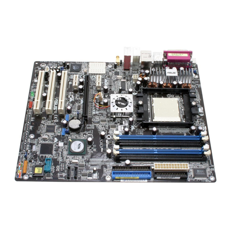
Page 27: Motherboard Layout
A S U S A 8 V - E D e l u x e A S U S A 8 V - E D e l u x e 24.5cm (9.6in) CHA_FAN2 CPU_FAN K8T890 PWR_FAN A8V-E DELUXE CLRTC CR2032 3V Lithium Cell CMOS Power USB56... -
Page 28: Layout Contents
2.2.4 2.2.4 2.2.4 2.2.4 2.2.4 Layout Contents Layout Contents Layout Contents Layout Contents Layout Contents S l o t s S l o t s S l o t s S l o t s S l o t s 1. - Page 29 I n t e r n a l c o n n e c t o r s I n t e r n a l c o n n e c t o r s I n t e r n a l c o n n e c t o r s I n t e r n a l c o n n e c t o r s I n t e r n a l c o n n e c t o r s 1.
-
Page 30: Central Processing Unit (Cpu)
Locate the CPU socket on the motherboard. A8V-E DELUXE ® A8V-E DELUXE CPU Socket 939 Before installing the CPU, make sure that the socket box is facing towards you and the load lever is on your left. 2 - 6... - Page 31 Unlock the socket by pressing the lever sideways, then lift it up to a 90 -100 angle. Make sure that the socket lever is lifted up to 90 -100 angle, otherwise the CPU does not fit in completely. Position the CPU above the socket such that the CPU corner with the gold triangle matches the socket corner with a small...
-
Page 32: Installing The Heatsink And Fan
2.3.3 2.3.3 Installing the heatsink and fan Installing the heatsink and fan 2.3.3 2.3.3 2.3.3 Installing the heatsink and fan Installing the heatsink and fan Installing the heatsink and fan The AMD Athlon™ 64FX or AMD Athlon 64™ processor require a specially designed heatsink and fan assembly to ensure optimum thermal condition and performance. - Page 33 Attach one end of the retention bracket to the retention module base. Align the other end of the retention bracket (near the retention bracket lock) to the retention module base. A clicking sound denotes that the retention bracket is in place. Make sure that the fan and heatsink assembly perfectly fits the retention mechanism...
-
Page 34: System Memory
The following figure illustrates the location of the sockets: A8V-E DELUXE ® A8V-E DELUXE 184-pin DDR DIMM sockets C h a n n e l C h a n n e l C h a n n e l C h a n n e l... -
Page 35: Memory Configurations
2.4.2 2.4.2 2.4.2 Memory Configurations Memory Configurations Memory Configurations 2.4.2 2.4.2 Memory Configurations Memory Configurations You may install 256 MB, 512 MB and 1 GB unbuffered ECC or non-ECC DDR DIMMs into the DIMM sockets using the memory configurations in this section. - Page 36 C C C C C - support for 4 modules inserted into the yellow and black slots as two pairs of Dual-channel memory configuration. Visit the ASUS website (www.asus.com) for the latest DDR400 Qualified Vendors List. 2 - 1 2...
-
Page 37: Installing A Dimm
2.4.3 2.4.3 Installing a DIMM Installing a DIMM 2.4.3 2.4.3 2.4.3 Installing a DIMM Installing a DIMM Installing a DIMM Make sure to unplug the power supply before adding or removing DIMMs or other system components. Failure to do so may cause severe damage to both the motherboard and the components. -
Page 38: Expansion Slots
Expansion slots In the future, you may need to install expansion cards. The following sub-sections describe the slots and the expansion cards that they support. Make sure to unplug the power cord before adding or removing expansion cards. Failure to do so may cause you physical injury and damage motherboard components. -
Page 39: Interrupt Assignments
2.5.3 2.5.3 Interrupt assignments Interrupt assignments 2.5.3 2.5.3 2.5.3 Interrupt assignments Interrupt assignments Interrupt assignments Standard interrupt assignments Standard interrupt assignments Standard interrupt assignments Standard interrupt assignments Standard interrupt assignments I R Q I R Q P r i o r i t y P r i o r i t y I R Q I R Q... -
Page 40: Pci Slots
2.5.4 2.5.4 PCI slots PCI slots 2.5.4 2.5.4 2.5.4 PCI slots PCI slots PCI slots The PCI slots support cards such as a LAN card, SCSI card, USB card, and other cards that comply with PCI specifications. The figure shows a LAN card installed on a PCI slot. -
Page 41: Jumpers
A8V-E DELUXE ® A8V-E DELUXE Clear RTC RAM You do not need to clear the RTC when the system hangs due to overclocking. For system failure due to overclocking, use the C.P.R. (CPU Parameter Recall) feature. Shut down and reboot the system so the BIOS can automatically reset parameter settings to default values. -
Page 42: Usb Device Wake-Up
USB ports. A8V-E DELUXE ® A8V-E DELUXE USB device wake-up • The USB device wake-up feature requires a power supply that can provide 500mA on the +5VSB lead for each USB port; otherwise, the system would not power up. - Page 43 A8V-E DELUXE ® A8V-E DELUXE Keyboard power setting A S U S A 8 V - E D e l u x e A S U S A 8 V - E D e l u x e A S U S A 8 V - E D e l u x e...
-
Page 44: Connectors
Connectors 2.7.1 2.7.1 Rear panel connectors Rear panel connectors 2.7.1 2.7.1 2.7.1 Rear panel connectors Rear panel connectors Rear panel connectors 1 . 1 . P a r a l l e l p o r t . P a r a l l e l p o r t . P a r a l l e l p o r t . - Page 45 W i F i - g ™ a n t e n n a p o r t . This port connects to the optional dipolar antenna for the onboard ASUS WiFi-g™ solution. ( Wireless Edition only ) 9 . 9 .
-
Page 46: Internal Connectors
DELUXE ® A8V-E DELUXE Floppy disk drive connector 2 . 2 . I D E c o n n e c t o r s ( 4 0 - 1 p i n P R I _ I D E , S E C _ I D E ) -
Page 47: Hard Disk Drives
A8V-E DELUXE A8V-E DELUXE SATA connectors I m p o r t a n t n o t e s o n S e r i a l A T A I m p o r t a n t n o t e s o n S e r i a l A T A... - Page 48 These are not jumpers! DO NOT place jumper caps on the fan connectors! • The ASUS Q-Fan2 function is supported using the CPU Fan (CPU_FAN) and Chassis Fan 1 (CHA_FAN1) connectors only. A8V-E DELUXE...
- Page 49 DELUXE ® A8V-E DELUXE COM port connector 6 . 6 . U S B c o n n e c t o r s ( 1 0 - 1 p i n U S B 5 6 , U S B 7 8 )
- Page 50 You must install a PSU with a higher power rating if you intend to install additional devices. A8V-E DELUXE ® A8V-E DELUXE ATX power connectors 2 - 2 8 2 - 2 8 2 - 2 8 2 - 2 8...
- Page 51 DELUXE ® A8V-E DELUXE Internal audio connectors 9 . 9 . G A M E / M I D I p o r t c o n n e c t o r ( 1 6 - 1 p i n G A M E )
- Page 52 A8V-E DELUXE ® A8V-E DELUXE Chassis alarm lead 1 1 . 1 1 . 1 1 . I E E E 1 3 9 4 c o n n e c t o r ( 1 0 - 1 p i n I E 1 3 9 4 _ 2 )
- Page 53 DELUXE ® A8V-E DELUXE Front panel audio connector 1 3 . 1 3 . D i g i t a l a u d i o c o n n e c t o r ( 4 - 1 p i n S P D I F ) 1 3 .
-
Page 54: System Panel Connector
This connector supports several chassis-mounted functions. A8V-E DELUXE ® A8V-E DELUXE System panel connector The sytem panel connector is color-coded for easy connection. Refer to the connector description below for details. • S y s t e m p o w e r L E D ( G r e e n 3 - p i n P L E D ) -
Page 55: Chapter 3: Powering Up
This chapter describes the power up sequence, the vocal POST messages, and ways of shutting down the system. Powering up... - Page 56 Chapter summary Starting up for the first time ... 3-1 Powering off the computer ... 3-2 ASUS POST Reporter™ ... 3-3 ASUS A8V-E Deluxe ASUS A8V-E Deluxe ASUS A8V-E Deluxe ASUS A8V-E Deluxe ASUS A8V-E Deluxe...
-
Page 57: Starting Up For The First Time
Starting up for the first time After making all the connections, replace the system case cover. Be sure that all switches are off. Connect the power cord to the power connector at the back of the system chassis. Connect the power cord to a power outlet that is equipped with a surge protector. -
Page 58: Powering Off The Computer
Powering off the computer 3.2.1 3.2.1 Using the OS shut down function Using the OS shut down function 3.2.1 3.2.1 3.2.1 Using the OS shut down function Using the OS shut down function Using the OS shut down function If you are using Windows Click the S t a r t S t a r t S t a r t... -
Page 59: Asus Post Reporter
ASUS POST Reporter™ This motherboard includes the Winbond speech controller to support a special feature called the ASUS POST Reporter™. This feature lets you hear vocal messages during POST that alerts you of system events and boot status. In case of a boot failure, you will hear the specific cause of the problem. - Page 60 Computer now booting from operating system You can enable or disable the ASUS POST Reporter™ in the S p e e c h C o n f i g u r a t i o n C o n f i g u r a t i o n C o n f i g u r a t i o n C o n f i g u r a t i o n option in the BIOS setup.
-
Page 61: Winbond Voice Editor
The Winbond Voice Editor software allows you to customize the vocal POST messages. You can install this application from the support CD. To avoid conflicts, do not run the Winbond Voice Editor while running the ASUS PC Probe application. Launching the Voice Editor Launching the Voice Editor... - Page 62 Y e s Y e s Y e s to confirm. Y e s The next time you boot your computer, the ASUS Post Reporter announces the messages in the selected language. 3 - 6 3 - 6 3 - 6...
- Page 63 Customizing your POST messages Customizing your POST messages Customizing your POST messages Customizing your POST messages Customizing your POST messages The Voice Editor application allows you to record your own POST messages if your language is not supported or if you wish to to replace the pre-installed wave files.
- Page 64 Select a POST event on the Voice Editor main window, then click the E d i t E d i t E d i t button. The E d i t E d i t E v e n t S o u n d E d i t o r E v e n t S o u n d E d i t o r window E v e n t S o u n d E d i t o r E v e n t S o u n d E d i t o r...
-
Page 65: Chapter 4: Bios Setup
This chapter tells how to change the system settings through the BIOS Setup menus. Detailed descriptions of the BIOS parameters are also provided. BIOS setup... - Page 66 BIOS setup program ... 4-11 Main menu ... 4-15 Advanced menu ... 4-18 Power menu ... 4-33 Boot menu ... 4-37 Exit menu ... 4-44 ASUS A8V-E Deluxe ASUS A8V-E Deluxe ASUS A8V-E Deluxe ASUS A8V-E Deluxe ASUS A8V-E Deluxe...
-
Page 67: Managing And Updating Your Bios
Save a copy of the original motherboard BIOS file to a bootable floppy disk in case you need to restore the BIOS in the future. Copy the original motherboard BIOS using the ASUS Update or AwardBIOS Flash utilities. 4.1.1 4.1.1... -
Page 68: Updating The Bios
AwardBIOS Flash Utility. Follow these instructions to update the BIOS using this utility. 1. Download the latest BIOS file from the ASUS web site. Rename the file to A 8 V - E . B I N A 8 V - E . B I N A 8 V - E . - Page 69 A S U S A 8 V - E D e l u x e A S U S A 8 V - E D e l u x e AwardBIOS Flash Utility for ASUS V1.01 (C) Phoenix Technologies Ltd. All Rights Reserved...
-
Page 70: Saving The Current Bios File
4 - 4 4 - 4 4 - 4 4 - 4 4 - 4 AwardBIOS Flash Utility for ASUS V1.01 (C) Phoenix Technologies Ltd. All Rights Reserved For K8T890-8237-A8V-E-00 Flash Type - PMC Pm49FL004T LPC/FWH File Name to Program: A8V-E.BIN... -
Page 71: Asus Crashfree Bios 2 Utility
ASUS CrashFree BIOS 2 utility ASUS CrashFree BIOS 2 utility The ASUS CrashFree BIOS 2 is an auto recovery tool that allows you to restore the BIOS file when it fails or gets corrupted during the updating process. You can update a corrupted BIOS file using the motherboard support CD or the floppy disk that contains the updated BIOS file. - Page 72 Restart the system after the utility completes the updating process. The recovered BIOS may not be the latest BIOS version for this motherboard. Visit the ASUS website (www.asus.com) to download the latest BIOS file. 4 - 6...
-
Page 73: Asus Ez Flash Utility
ASUS EZ Flash utility ASUS EZ Flash utility The ASUS EZ Flash feature allows you to update the BIOS without having to go through the long process of booting from a floppy disk and using a DOS-based utility. The EZ Flash utility is built-in the BIOS chip so it is accessible by pressing <Alt>... -
Page 74: Asus Update Utility
4.1.6 4.1.6 ASUS Update utility ASUS Update utility The ASUS Update is a utility that allows you to manage, save, and update the motherboard BIOS in Windows allows you to: • Save the current BIOS file • Download the latest BIOS file from the Internet •... - Page 75 Updating the BIOS through the Internet Updating the BIOS through the Internet To update the BIOS through the Internet: Launch the ASUS Update utility from the Windows S t a r t S t a r t S t a r t > P r o g r a m s...
- Page 76 A S U S U p d a t e A S U S U p d a t e. The ASUS Update main window appears. U p d a t e B I O S f r o m a...
-
Page 77: Bios Setup Program
• Visit the ASUS website (www.asus.com) to download the latest BIOS file for this motherboard and . A S U S A 8 V - E D e l u x e... -
Page 78: Bios Menu Screen
The BIOS setup screens shown in this chapter are for reference purposes only, and may not exactly match what you see on your screen. • Visit the ASUS website (www.asus.com) to download the latest BIOS information. 4 - 1 2 4 - 1 2... -
Page 79: Legend Bar
4.2.3 4.2.3 4.2.3 Legend bar Legend bar Legend bar 4.2.3 4.2.3 Legend bar Legend bar At the bottom of the Setup screen is a legend bar. The keys in the legend bar allow you to navigate through the various setup menus. The following table lists the keys found in the legend bar with their corresponding functions. -
Page 80: General Help
Boot Exit 15 : 30 : 36 Wed, Sep 15 2004 [1.44M, 3.5 in.] Legacy Diskette A: [ST321122A] [ASUS CDS520/A] Disabled ... [ ] [None] 360K , 5.25 in..[ ] [None] 1.2M , 5.25 in..[ ] [Disabled] 720K , 3.5 in. -
Page 81: Main Menu
A S U S A 8 V - E D e l u x e Boot Exit : 30 : 36 Wed, Sep 15 2004 [English] [1.44M, 3.5 in.] [ST321122A] [ASUS CDS520/A] [None] [None] [Disabled] 256MB -/+: Change Value Enter: Select Sub-menu Select Menu... -
Page 82: Primary And Secondary Ide Master/Slave
4.3.5 4.3.5 4.3.5 Primary and Secondary IDE Master/Slave Primary and Secondary IDE Master/Slave Primary and Secondary IDE Master/Slave 4.3.5 4.3.5 Primary and Secondary IDE Master/Slave Primary and Secondary IDE Master/Slave While entering Setup, the BIOS automatically detects the presence of IDE devices. -
Page 83: Installed Memory
Capacity Capacity Capacity Capacity Capacity Displays the auto-detected hard disk capacity. This item is not configurable. Cylinder Cylinder Cylinder Cylinder Cylinder Shows the number of the hard disk cylinders. This item is not configurable. H e a d H e a d H e a d H e a d H e a d... -
Page 84: Advanced Menu
This feature requires the AMD CPU heatsink and fan assembly with monitor chip. If you purchased a separate heatsink and fan package, use the ASUS Q-Fan Technology feature to automatically adjust the CPU fan speed according to your system loading. -
Page 85: Chipset
4.4.2 4.4.2 Chipset Chipset 4.4.2 4.4.2 4.4.2 Chipset Chipset Chipset Phoenix-Award BIOS CMOS Setup Utility Advanced Chipset DRAM Configuration Upstream LDT Bus Width Downstream LDT Bus Width LDT Bus Frequency VLink Mode Selection PEG Data Scrambling PE0-PE3 Data Scrambling Init Display First Chipset Vcore Adjustment F1:Help : Select Item... - Page 86 CAS# latency (Tcl) [Auto] Controls the latency between the SDRAM read command and the time the data actually becomes available. Configuration options: [Auto] [2.0] [2.5] [3.0] RAS# to CAS# delay (Trcd) [Auto] Controls the latency between the DDR SDRAM active command and the read/write command.
-
Page 87: Pci Pnp
PE0-PE3 Data Scrambling [Enable] PE0-PE3 Data Scrambling [Enable] PE0-PE3 Data Scrambling [Enable] PE0-PE3 Data Scrambling [Enable] PE0-PE3 Data Scrambling [Enable] Disables or enables the PCI Express™ 0 to PCI Express™ 3 data scrambling. Configuration options: [Disable] [Enable] Init Display First [PCI Slot] Init Display First [PCI Slot] Init Display First [PCI Slot] Init Display First [PCI Slot]... - Page 88 When the item Resources Controlled By is set to [Auto], the item IRQ Resources is grayed out and not user-configurable. Refer to the section “IRQ Resources” for information on how to enable this item. IRQ Resources IRQ Resources IRQ Resources IRQ Resources IRQ Resources This sub-menu is activated only when the R e s o u r c e s C o n t r o l l e d B y...
-
Page 89: Onboard Devices Configuration
4.4.4 4.4.4 4.4.4 Onboard Devices Configuration Onboard Devices Configuration Onboard Devices Configuration 4.4.4 4.4.4 Onboard Devices Configuration Onboard Devices Configuration Phoenix-Award BIOS CMOS Setup Utility Advanced Onboard Device Configuration Onboard 1394 Controller Onboard PCIE GbE LAN Onboard LAN Boot ROM Onboard Wireless LAN OnChip SATA SATA Mode... - Page 90 Onboard AC97 Audio [Auto] Onboard AC97 Audio [Auto] Onboard AC97 Audio [Auto] Onboard AC97 Audio [Auto] Onboard AC97 Audio [Auto] Allows you to disable or set the onboard AC97 audio controller. Configuration options: [Disabled] [Auto] Serial Port1 Address [3F8/IRQ4] Serial Port1 Address [3F8/IRQ4] Serial Port1 Address [3F8/IRQ4] Serial Port1 Address [3F8/IRQ4] Serial Port1 Address [3F8/IRQ4]...
-
Page 91: Usb Configuration
4.4.5 4.4.5 4.4.5 USB Configuration USB Configuration USB Configuration 4.4.5 4.4.5 USB Configuration USB Configuration The items in this menu allows you to change the USB-related features. Select an item then press <Enter> to display the configuration options. Phoenix-Award BIOS CMOS Setup Utility Advanced USB Configuration OnChip USB Controller... -
Page 92: Jumperfree Configuration
Loads the optimal settings for the system. Loads the standard settings for the system. Loads overclocking profiles with optimal parameters for stability when overclocking. The ASUS AI Non-delay Overclocking System feature intelligently determines the system load and automatically boost the performance for the most demanding tasks. - Page 93 The following items are user-configurable only when the AI Overclocking item is set to [Manual]. Phoenix-Award BIOS CMOS Setup Utility Advanced JumperFree Configuration Overclock Profile x Overclock Options x N.O.S. Option Frequency Configuration CPU Multiplier Hammer Vid control Memory Voltage Adjustment CPU Vcore Adjustment F1:Help : Select Item...
- Page 94 PCIEx clock Sync. to CPU [Enable] Enables or disables the PCI Express™ synchronous clock to the CPU. Configuration options: [Disabled] [Enabled] PCIEx Clock [XXX] (value is auto-detected) Allows you to set the PCI Express clock frequency. This item is user-configurable only when the P C I E x c l o c k S y n c . t o C P U set to Disabled.
- Page 95 Hammer Vid control [Startup] Hammer Vid control [Startup] Hammer Vid control [Startup] Hammer Vid control [Startup] Hammer Vid control [Startup] Sets the Hammer Voltage ID control. Configuration options: [Startup] [1.5625v] [1.550 v] [1.5375v] [1.525 v] [1.5125v] [1.500 v] [1.4875v] [1.475 v] [1.4625v] [1.450 v] [1.4375v] [1.425 v] [1.4125v] [1.400 v] [1.3875v] [1.375 v] [1.3625v] [1.350 v] [1.3375v] [1.325 v] [1.3125v] [1.300 v] [1.2875v] [1.275 v] [1.2625v] [1.250 v] [1.2375v] [1.225 v] [1.2125v] [1.200 v] [1.1875v] [1.175 v] [1.1625v] [1.150 v] [1.1375v]...
-
Page 96: Lan Cable Status
4.4.7 4.4.7 4.4.7 LAN Cable Status LAN Cable Status LAN Cable Status 4.4.7 4.4.7 LAN Cable Status LAN Cable Status The items in this menu displays the status of the Local Area Network (LAN) cable. Advanced JumperFree Configuration POST Check LAN Cable Pair F1:Help : Select Item... -
Page 97: Speech Configuration
Speech IC Reporter [Enabled] Speech IC Reporter [Enabled] Speech IC Reporter [Enabled] Allows you to enable or disable the ASUS Speech POST Reporter™ feature. Configuration options: [Disabled] [Enabled] The following items appear only when Speech POST Reporter is set to Enabled. -
Page 98: Instant Music
Instant Music [Disabled] Instant Music [Disabled] Instant Music [Disabled] Instant Music [Disabled] Allows you to enable or disable the ASUS Instant Music feature. Configuration options: [Disabled] [Enabled] Enabling Instant Music automatically disables the PS/2 keyboard power up feature. Instant Music CD-ROM Drive [Primary Master]... -
Page 99: Power Menu
Power menu The Power menu items allow you to change the settings for the Advanced Configuration and Power Interface (ACPI) and the Advanced Power Management (APM). Select an item then press <Enter> to display the configuration options. Phoenix-Award BIOS CMOS Setup Utility Main Advanced Power... -
Page 100: Apm Configuration
4.5.3 4.5.3 4.5.3 APM Configuration APM Configuration APM Configuration 4.5.3 4.5.3 APM Configuration APM Configuration Power APM Configuration PS2KB Wakeup from S5 PS2MS Wakeup from S5 USB Resume from Power Up On PCI Devices Modem Ring Resume Power On By RTC Alarm x Date (of Month) x Resume Time (hh:mm:ss) Restore on AC Power Loss... - Page 101 Power On By RTC Alarm [Disabled] Power On By RTC Alarm [Disabled] Power On By RTC Alarm [Disabled] Power On By RTC Alarm [Disabled] Power On By RTC Alarm [Disabled] Allows you to enable or disable RTC to generate a wake event. When this item is set to Enabled, the items Date (of Month) and Resume Time (hh:mm:ss) become configurable with set values.
-
Page 102: Hardware Monitor
Q-FAN Function [Disabled] Q-FAN Function [Disabled] Q-FAN Function [Disabled] Q-FAN Function [Disabled] Q-FAN Function [Disabled] Allows you to disable or enable the ASUS Q-Fan function. Configuration options: [Disabled] [Enabled] 4 - 3 6 4 - 3 6 4 - 3 6... -
Page 103: Boot Menu
CPU Target Temperature [xxxºC/xxxºF] CPU Target Temperature [xxxºC/xxxºF] CPU Target Temperature [xxxºC/xxxºF] CPU Target Temperature [xxxºC/xxxºF] CPU Target Temperature [xxxºC/xxxºF] Allows you to set the CPU Q-Fan temperature threshold when the CPU fan speed is increased to lower the CPU temperature. Configuration options: [10ºC/50ºF] [15ºC/59ºF] [20ºC/68ºF] [25ºC/77ºF] [30ºC/86ºF] [35ºC/95ºF] [40ºC/104ºF] [45ºC/113ºF] [50ºC/122ºF] [55ºC/131ºF] [60ºC/140ºF] [65ºC/149ºF] [70ºC/158ºF] [75ºC/167ºF]... -
Page 104: Boot Device Priority
4.6.1 4.6.1 4.6.1 4.6.1 4.6.1 Boot Device Priority Boot Device Priority Boot Device Priority Boot Device Priority Boot Device Priority Power Boot Device Priority 1st Boot Device 2nd Boot Device 3rd Boot Device 4th Boot Device F1:Help : Select Item ESC: Exit : Select Menu 1st ~ xxth Boot Device [Removable]... -
Page 105: Hard Disk Drives
4.6.3 4.6.3 4.6.3 Hard Disk Drives Hard Disk Drives Hard Disk Drives 4.6.3 4.6.3 Hard Disk Drives Hard Disk Drives Phoenix-Award BIOS CMOS Setup Utility Hard Disk Drives 1. 1st Master: XXXXXXXXX 2. Bootable Add-in Cards F1:Help : Select Item ESC: Exit : Select Menu 1. -
Page 106: Boot Settings Configuration
4.6.5 4.6.5 4.6.5 Boot Settings Configuration Boot Settings Configuration Boot Settings Configuration 4.6.5 4.6.5 Boot Settings Configuration Boot Settings Configuration Boot Settings Configuration Case Open Warning Quick Boot Boot Up Floppy Seek Bootup Num-Lock Typematic Rate Setting x Typematic Rate (Chars/Sec) x Typematic Delay (Msec) OS Select For DRAM >... - Page 107 Allows you to enable or disable the full screen logo display feature. Configuration options: [Disabled] [Enabled] Make sure that the above item is set to [Enabled] if you want to use the ASUS MyLogo2™ feature. Halt On [All, But Keyboard] Halt On [All, But Keyboard]...
-
Page 108: Security
4.6.6 4.6.6 4.6.6 4.6.6 4.6.6 Security Security Security Security Security Boot Settings Configuration Supervisor Password User Password Password Check F1:Help : Select Item ESC: Exit : Select Menu Supervisor Password Supervisor Password Supervisor Password Supervisor Password Supervisor Password User Password User Password User Password User Password... - Page 109 A n o t e a b o u t p a s s w o r d s A n o t e a b o u t p a s s w o r d s A n o t e a b o u t p a s s w o r d s A n o t e a b o u t p a s s w o r d s A n o t e a b o u t p a s s w o r d s The Supervisor password is required to enter the BIOS Setup program...
-
Page 110: Exit Menu
Exit menu The Exit menu items allow you to load the optimal or failsafe default values for the BIOS items, and save or discard your changes to the BIOS items. Main Advanced Power Exit & Save Changes Exit & Discard Changes Load Setup Default Discard Changes F1:Help... - Page 111 Load Setup Defaults Load Setup Defaults Load Setup Defaults Load Setup Defaults Load Setup Defaults This option allows you to load the default values for each of the parameters on the Setup menus. When you select this option or if you press <F5>, a confirmation window appears.
- Page 112 4 - 4 6 4 - 4 6 4 - 4 6 4 - 4 6 4 - 4 6 C h a p t e r 4 : B I O S s e t u p C h a p t e r 4 : B I O S s e t u p C h a p t e r 4 : B I O S s e t u p C h a p t e r 4 : B I O S s e t u p C h a p t e r 4 : B I O S s e t u p...
- Page 113 This chapter describes the contents of the support CD that comes with the motherboard package. Software support...
- Page 114 Support CD information ... 5-1 Software information ... 5-9 RAID configurations ... 5-18 Creating a RAID driver disk ... 5-26 Cool ‘n’ Quiet!™ Technology ... 5-27 ASUS A8V-E Deluxe ASUS A8V-E Deluxe ASUS A8V-E Deluxe ASUS A8V-E Deluxe ASUS A8V-E Deluxe...
-
Page 115: Installing An Operating System
The support CD that came with the motherboard package contains the drivers, software applications, and utilities that you can install to avail all motherboard features. The contents of the support CD are subject to change at any time without notice. Visit the ASUS website(www.asus.com) for updates. 5.2.1 5.2.1 5.2.1... -
Page 116: Drivers Menu
5.2.2 5.2.2 5.2.2 Drivers menu Drivers menu Drivers menu 5.2.2 5.2.2 Drivers menu Drivers menu The drivers menu shows the available device drivers if the system detects installed devices. Install the necessary drivers to activate the devices. VIA 4 in 1 drivers VIA 4 in 1 drivers VIA 4 in 1 drivers VIA 4 in 1 drivers... - Page 117 ASUS Wireless LAN adapter Drivers and Utility ASUS Wireless LAN adapter Drivers and Utility ASUS Wireless LAN adapter Drivers and Utility Installs the driver, utilities, and setup wizard for the ASUS WiFi-g™ wireless solution. Refer to the WiFi-g™ documentation for details. USB 2.0 Driver USB 2.0 Driver...
-
Page 118: Utilities Menu
See page 5-11 for details. AI Booster AI Booster AI Booster AI Booster AI Booster The ASUS AI Booster application allows you to overclock the CPU speed in a Windows ® environment. ASUS PC Probe ASUS PC Probe... - Page 119 Winbond Voice Editor Winbond Voice Editor This program is for recording and customizing wave files for the ASUS POST Reporter™. Use this program to change the default vocal POST messages. See section “3.3 Vocal POST Messages” for a list of the default messages.
-
Page 120: Asus Contact Information
C o n t a c t C o n t a c t C o n t a c t tab to display the ASUS contact information. You can C o n t a c t also find this information on the inside front cover of this user guide. - Page 121 Technical support Form Technical support Form Technical support Form Displays the ASUS Technical Support Request Form that you have to fill out when requesting technical support. A S U S A 8 V - E D e l u x e...
- Page 122 Filelist Filelist Filelist Filelist Filelist Displays the contents of the support CD and a brief description of each in text format. 5 - 8 5 - 8 5 - 8 5 - 8 5 - 8 C h a p t e r 5 : S o f t w a r e s u p p o r t C h a p t e r 5 : S o f t w a r e s u p p o r t C h a p t e r 5 : S o f t w a r e s u p p o r t C h a p t e r 5 : S o f t w a r e s u p p o r t...
-
Page 123: Software Information
ASUS MyLogo2™ ASUS MyLogo2™ ASUS MyLogo2™ The ASUS MyLogo2™ utility lets you customize the boot logo. The boot logo is the image that appears on screen during the Power-On Self-Tests (POST). The ASUS MyLogo2™ is automatically installed when you install the A S U S U p d a t e A S U S U p d a t e utility from the support CD. - Page 124 R a t i o box. R a t i o When the screen returns to the ASUS Update utility, flash the original BIOS to load the new boot logo. 10. After flashing the BIOS, restart the computer to display the new boot logo during POST.
-
Page 125: Ai Net 2
5.3.2 5.3.2 5.3.2 5.3.2 5.3.2 AI NET 2 AI NET 2 AI NET 2 AI NET 2 AI NET 2 The Marvell ® Virtual Cable Tester™ (VCT) is a cable diagnostic utility that reports LAN cable faults and shorts using the Time Domain Reflectometry (TDR) technology. -
Page 126: Audio Configurations
5.3.3 5.3.3 Audio configurations Audio configurations 5.3.3 5.3.3 5.3.3 Audio configurations Audio configurations Audio configurations The Realtek ® ALC850 AC ‘97 audio CODEC provides 8-channel audio capability to deliver the ultimate audio experience on your PC. The software provides Jack-Sensing function (Line-In, Line-Out, Mic-In), S/PDIF out support and interrupt capability. - Page 127 To set the sound effect options: From the Realtek Audio Control Panel, click the S o u n d E f f e c t button. Click the shortcut buttons to change the acoustic environment, adjust the equalizer, or set the karaoke to your desired settings. The audio settings take effect immediately after you click on the buttons.
- Page 128 Speaker Configuration Speaker Configuration Speaker Configuration Speaker Configuration Speaker Configuration This option allows you to set your speaker configuration. To set the speaker configuration: From the Realtek Audio Control Panel, click the S p e a k e r C o n f i g u r a t i o n C o n f i g u r a t i o n C o n f i g u r a t i o n button.
- Page 129 AI Audio feature AI Audio feature AI Audio feature AI Audio feature AI Audio feature The AI Audio feature works through the connector sensing option that allows you to check if your audio devices are connected properly. To start the connector sensing: From the Realtek Audio Control Panel, click the C o n n e c t o r S e n s i n g button.
- Page 130 If there are detected problems, make sure that your audio cables are connected to the proper audio jack and repeat connector sensing. Click the X X X X X button to exit EZ-connection dialog box. Click the Exit (X X X X X ) button on the upper-right hand corner of the window to exit audio control panel.
- Page 131 General settings General settings General settings General settings General settings This option shows the audio settings and allows you to change the language setting or toggle the SoundEffect icon display on the Windows taskbar. To display the general settings: From the Realtek Audio Control Panel, click the G e n e r a l Click the option button to enable or disable the icon display on the Windows taskbar.
-
Page 132: Raid Configurations
RAID configurations The motherboard comes with the VIA VT8237R Southbridge RAID controller that allows you to configure Serial ATA hard disk drives as RAID sets. The motherboard supports the following RAID configurations. R A I D 0 R A I D 0 (Data striping) optimizes two identical hard disk drives to read and R A I D 0 R A I D 0 R A I D 0... -
Page 133: Via Raid Configurations
5.4.2 5.4.2 5.4.2 5.4.2 5.4.2 VIA RAID configurations VIA RAID configurations VIA RAID configurations VIA RAID configurations VIA RAID configurations The motherboard includes a high performance IDE RAID controller integrated in the VIA VT8237R southbridge chipset. It supports RAID 0 and RAID 1 with two independent Serial ATA channels. - Page 134 Create Array Create Array Create Array Create Array Create Array From the VIA RAID BIOS utility main menu, select C r e a t e A r r a y < E n t e r > < E n t e r > press <...
- Page 135 Press <Y> to confirm or <N> to return to the configuration options. If you selected <Y>, proceed to step 9. Select S e l e c t D i s k D r i v e s S e l e c t D i s k D r i v e s, then press <Enter>. Use arrow keys to S e l e c t D i s k D r i v e s S e l e c t D i s k D r i v e s S e l e c t D i s k D r i v e s...
- Page 136 From this point, you can auto-configure the RAID array by selecting A u t o S e t u p f o r D a t a S e c u r i t y A u t o S e t u p f o r D a t a S e c u r i t y A u t o S e t u p f o r D a t a S e c u r i t y A u t o S e t u p f o r D a t a S e c u r i t y A u t o S e t u p f o r D a t a S e c u r i t y or manually configure the RAID...
- Page 137 RAID Span for capacity RAID Span for capacity RAID Span for capacity RAID Span for capacity RAID Span for capacity 1. From the create array menu, select A r r a y M o d e The supported RAID configurations appear on a pop-up menu. RAID 0 for performance RAID 1 for data protection RAID 0/1...
- Page 138 10. Press <Y> to confirm or <N> to return to the configuration options. 11. Press <Esc> to go back to main menu. Delete Array Delete Array Delete Array Delete Array Delete Array From the VIA RAID BIOS utility main menu, select D e l e t e A r r a y press <Enter>.
- Page 139 Serial Number View Serial Number View Serial Number View Serial Number View Serial Number View From the VIA RAID BIOS utility main menu, select S e r i a l N u m b e r V i e w V i e w V i e w V i e w...
-
Page 140: Creating A Raid Driver Disk
Creating a RAID driver disk A floppy disk with the RAID driver is required when installing Windows 2000/XP operating system on a hard disk drive that is included in a RAID set. To create a RAID driver disk: Place the motherboard support CD into the CD-ROM drive. D r i v e r s D r i v e r s When the D r i v e r s... -
Page 141: Cool 'N' Quiet!™ Technology
Cool ‘n’ Quiet!™ Technology The motherboard supports the AMD Cool ‘n’ Quiet!™ Technology that dynamically and automatically change the CPU speed, voltage, and amount of power depending on the task the CPU performs. 5.6.1 5.6.1 5.6.1 5.6.1 5.6.1 Enabling Cool ‘n’ Quiet!™ Technology Enabling Cool ‘n’... -
Page 142: Launching The Cool 'N' Quiet!™ Software
5.6.2 5.6.2 5.6.2 5.6.2 5.6.2 Launching the Cool ‘n’ Quiet!™ software Launching the Cool ‘n’ Quiet!™ software Launching the Cool ‘n’ Quiet!™ software Launching the Cool ‘n’ Quiet!™ software Launching the Cool ‘n’ Quiet!™ software The motherboard support CD includes the Cool ‘n’ Quiet!™ software that enables you to view your system’s real-time CPU Frequency and voltage.