Asus A8V User Manual
Hide thumbs
Also See for A8V:
- User manual (144 pages) ,
- Quick setup manual (10 pages) ,
- Update manual (2 pages)
Table of Contents
Advertisement
Advertisement
Table of Contents

Related Manuals for Asus A8V


Summary of Contents for Asus A8V
- Page 1 User Guide...
- Page 2 Product warranty or service will not be extended if: (1) the product is repaired, modified or altered, unless such repair, modification of alteration is authorized in writing by ASUS; or (2) the serial number of the product is defaced or missing.
-
Page 3: Table Of Contents
How this guide is organized ..........ix Where to find more information ..........ix Conventions used in this guide ..........x Typography ................x A8V specifications summary ............xi Chapter 1: Product introduction 1.1 Welcome! ................1-1 1.2 Package contents ............... 1-1 1.3 Special features .............. - Page 4 Using AFUDOS to update the BIOS ...... 4-2 4.1.3 Using AFUDOS to copy BIOS from PC ....4-3 4.1.4 Using ASUS EZ Flash to update the BIOS .... 4-4 4.1.5 Recovering the BIOS with CrashFree BIOS 2 ..4-5 4.1.6 ASUS Update ............
- Page 5 Drivers menu ............5-2 5.2.3 Utilities menu ............5-3 5.2.4 Manuals menu ............5-4 5.2.5 ASUS Contact information ........5-4 5.2.6 Other information ........... 5-5 5.3 Software Information ............5-7 ASUS MyLogo2™ .............. 5-7 5.4 AI Net feature ..............5-9 5.5 Audio configurations ............
- Page 6 Contents 5.8 Cool ‘n’ Quiet!™ Technology ..........5-21 5.8.1 Enabling Cool ‘n’ Quiet!™ Technology ....5-21 5.8.2 Launching the Cool ‘n’ Quiet!™ software ..... 5-23...
-
Page 7: Notices
Notices Federal Communications Commission Statement This device complies with Part 15 of the FCC Rules. Operation is subject to the following two conditions: • This device may not cause harmful interference, and • This device must accept any interference received including interference that may cause undesired operation. -
Page 8: Safety Information
Safety information Electrical safety • To prevent electrical shock hazard, disconnect the power cable from the electrical outlet before relocating the system. • When adding or removing devices to or from the system, ensure that the power cables for the devices are unplugged before the signal cables are connected. -
Page 9: About This Guide
Refer to the following sources for additional information and for product and software updates. 1. ASUS websites The ASUS website provides updated information on ASUS hardware and software products. Refer to the ASUS contact information. 2. Optional documentation Your product package may include optional documentation, such as warranty flyers, that may have been added by your dealer. -
Page 10: Conventions Used In This Guide
Conventions used in this guide To make sure that you perform certain tasks properly, take note of the following symbols used throughout this manual. DANGER/WARNING: Information to prevent injury to yourself when trying to complete a task. CAUTION: Information to prevent damage to the components when trying to complete a task. -
Page 11: A8V Specifications Summary
CPU, Memory, and AGP voltage adjustable Features SFS (Stepless Frequency Selection) from 200 MHz up to 300 MHz at 1 MHz increment ASUS JumperFree ASUS C.P.R. (CPU Parameter Recall) Special features ASUS EZ Flash ASUS CrashFree BIOS 2 ASUS MyLogo2™... - Page 12 A8V specifications summary 2 x USB 2.0 connectors for 4 additional USB ports Internal I/O CPU/Chassis/Power fan connectors 20-pin/4-pin ATX 12V power connectors CD/AUX connectors GAME/MIDI connector Front panel audio connector System panel connector 4Mb Flash EEPROM BIOS features AMI BIOS with enhanced ACPI, PnP, DMI2.0, Green PCI 2.2, USB 2.0/1.1...
-
Page 13: Chapter 1: Product Introduction
Chapter 1 This chapter describes the motherboard features and the new technologies it supports. Product introduction... - Page 14 Chapter summary Welcome! ............1-1 Package contents .......... 1-1 Special features ..........1-2 ASUS A8V...
-
Page 15: Welcome
® The motherboard delivers a host of new features and latest technologies, making it another standout in the long line of ASUS quality motherboards! Before you start installing the motherboard, and hardware devices on it, check the items in your package with the list below. -
Page 16: Special Features
Special features 1.3.1 Product highlights Latest processor technology The AMD Athlon™ 64FX and Athlon™ 64 desktop processors are based on AMD’s 64-bit and 32-bit architecture, which represents the landmark introduction of the industry’s first x86-64 technology. These processors provide a dramatic leap forward in compatibility, performance, investment protection, and reduced total cost of ownership and development. - Page 17 480 Mbps on USB 2.0 - supporting up to eight USB 2.0 ports. The higher bandwidth of USB 2.0 allows connection of devices such as high resolution video conferencing cameras, next generation scanners and printers, and fast storage units. USB 2.0 is backward compatible with USB 1.1. See pages 2-21. ASUS A8V...
-
Page 18: Unique Asus Features
See page 4-32. CrashFree BIOS 2 This feature allows you to restore the original BIOS data from the ASUS support CD in case when the BIOS codes and data are corrupted. This protection eliminates the need to buy a replacement ROM chip. See page 4-5. - Page 19 ASUS EZ Flash BIOS With the ASUS EZ Flash, you can easily update the system BIOS even before loading the operating system. No need to use a DOS-based utility or boot from a floppy disk. See page 4-4.
- Page 20 Chapter 1: Product introduction...
-
Page 21: Chapter 2: Hardware Information
Chapter 2 This chapter lists the hardware setup procedures that you have to perform when installing system components. It includes description of the jumpers and connectors on the motherboard. Hardware information... - Page 22 Chapter summary Before you proceed ........2-1 Motherboard overview ........2-2 Central Processing Unit (CPU) ..... 2-6 System memory ..........2-11 Expansion slots ........... 2-15 Jumpers ............2-18 Connectors ........... 2-20 ASUS A8V motherboard...
-
Page 23: Before You Proceed
The illustration below shows the location of the onboard LED. SB_PWR ® Standby Powered Power A8V Onboard LED ASUS A8V... -
Page 24: Motherboard Overview
Motherboard overview Before you install the motherboard, study the configuration of your chassis to ensure that the motherboard fits into it. Unplug the power cord before installing or removing the motherboard. Failure to do so can cause you physical injury and damage motherboard components. -
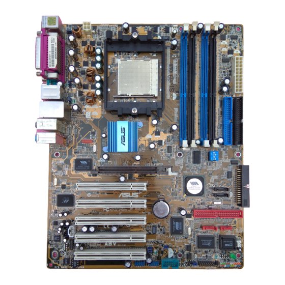
Page 25: Motherboard Layout
CMOS Power Normal Clear CMOS (Default) PCI3 Speaker Connector Power LED PCI4 Realtek Super ALC850 4Mbit BIOS CLRTC USBPWR56 PCI5 SB_PWR FP_AUDIO USBPWR78 Reset SW GAME USB78 USB56 PANEL ATX Power IDE_LED Switch* Requires an ATX power supply. ASUS A8V... -
Page 26: Layout Contents
2.2.4 Layout Contents Slots Page 1. DDR DIMM slots 2-11 2. PCI slots 2-17 3. AGP slot 2-17 Jumpers Page 1. Clear RTC RAM (3-pin CLRTC) 2-18 2. Keyboard power (3-pin KBPWR) 2-19 3. USB device wake-up (3-pin USBPWR12, USBPWR34, USBPWR56, USBPWR78) 2-19 Rear Panel Connectors... - Page 27 15. System panel connector (20-pin PANEL) 2-28 - System power LED (Green 3-pin PLED) - System warning speaker (Orange 4-pin SPEAKER) - Reset switch (Blue 2-pin RESET) - ATX Power switch (Yellow 2-pin PWRSW) - Hard Disk activity LED (Red 2-pin IDE_LED) ASUS A8V...
-
Page 28: Central Processing Unit (Cpu)
Gold triangle 2.3.2 Installing the CPU Follow these steps to install a CPU. 1. Locate the 939-pin ZIF socket on the motherboard. ® Gold Arrow A8V CPU Socket 939 Chapter 2: Hardware information... - Page 29 CPU! 5. When the CPU is in place, push down the socket lever to secure the CPU. The lever clicks on the side tab to indicate that it is locked. ASUS A8V...
-
Page 30: Installing The Heatsink And Fan
2.3.3 Installing the heatsink and fan The AMD Athlon™ 64FX or AMD Athlon 64™ processor require a specially designed heatsink and fan assembly to ensure optimum thermal condition and performance. Make sure that you use only qualified heatsink and fan assembly. Follow these steps to install the CPU heatsink and fan. - Page 31 4. Push down the retention bracket lock on the retention mechanism to secure the heatsink and fan to the module base. ASUS A8V...
-
Page 32: Connecting The Cpu Fan Cable
CPU_FAN. CPU_FAN ® A8V CPU fan connector Do not forget to connect the CPU fan connector! CPU overheating and hardware monitoring errors may occur if you _ to plug this connector. 2-10... -
Page 33: System Memory
Memory Module (DIMM) sockets. The following figure illustrates the location of the sockets. ® A8V 184-pin DDR DIMM sockets 2.4.2 Memory configurations You may install 64MB, 128MB, 256MB, 512MB, and 1GB unbuffered ECC and non-ECC DDR DIMMs into the DIMM sockets using the memory configurations in this section. - Page 34 Table 1 Recommended memory configurations Sockets Mode DIMM_A1 DIMM_A2 DIMM_B1 DIMM_B2 Single-channel — — Populated — Dual-channel* (1) Populated — Populated — (2) Populated Populated Populated Populated * Use only identical DDR DIMM pairs. * For dual-channel configuration (3), you may: •...
-
Page 35: Ddr Qualified Vendors List
C* - Supports 4 modules inserted into both the blue and black slots as two pairs of Dual-channel memory configuration. Visit the ASUS website (www.asus.com) for the latest DDR 400 Qualified Vendor List for this motherboard. Obtain DDR DIMMs only from ASUS qualified vendors for better system performance. -
Page 36: Installing A Dimm
2.4.3 Installing a DIMM Make sure to unplug the power supply before adding or removing DIMMs or other system components. _ure to do so may cause severe damage to both the motherboard and the components. 1. Unlock a DIMM socket by DDR DIMM NOTCH pressing the retaining clips outward. -
Page 37: Expansion Slots
1. Turn on the system and change the necessary BIOS settings, if any. See Chapter 4 for information on BIOS setup. 2. Assign an IRQ to the card. Refer to the tables on the next page. 3. Install the software drivers for the expansion card. ASUS A8V 2-15... -
Page 38: Interrupt Assignments
2.5.3 Interrupt assignments Standard Interrupt Assignments Priority Standard Function System Timer Keyboard Controller Programmable Interrupt IRQ Holder for PCI Steering Communications Port (COM1) Sound Card (sometimes LPT2) Floppy Disk Controller Printer Port (LPT1) System CMOS/Real Time Clock ACPI Mode when used IRQ Holder for PCI Steering IRQ Holder for PCI Steering PS/2 Compatible Mouse Port... -
Page 39: Pci Slots
Install only 1.5V AGP cards on this motherboard! 3.3V AGP cards are not supported in this motherboard. ® Keyed for 1.5v A8V Accelerated Graphics Port (AGP) ® If installing the ATI 9500 or 9700 Pro Series VGA cards, use only the card version PN xxx-xxxxx-30 or later, for optimum performance and overclocking stability. -
Page 40: Jumpers
CLRTC ® Normal Clear CMOS A8V Clear RTC RAM (Default) You do not need to clear the RTC when the system hands due to overclocking. For system failure due to overclocking, use the C.P.R. (CPU Parameter Recall) feature. Shut down and reboot the system so the BIOS can automatically reset the parameter settings to the default values. - Page 41 (Default) USBPWR56 ® USBPWR78 +5VSB A8V USB device wake up (Default) • The USB device wake-up feature requires a power supply that can provide 500mA on the +5VSB lead for each USB port. Otherwise, the system would not power up.
-
Page 42: Connectors
Connectors 2.7.1 Rear panel connectors 1. PS/2 mouse port. This green 6-pin connector is for a PS/2 mouse. 2. Parallel port. This 25-pin port connects a parallel printer, a scanner, or other devices. 3. RJ-45 port. This port allows connection to a Local Area Network (LAN) through a network hub. - Page 43 12. Serial connector. This 9-pin COM1 port is for serial devices. 13. S/PDIF coaxial out port. This port connects to external audio output devices with coaxial cable connectors. 14. PS/2 keyboard port. This purple connector is for a PS/2 keyboard. ASUS A8V 2-21...
-
Page 44: Internal Connectors
(Pin 5 is removed to prevent incorrect insertion when using ribbon cables with pin 5 plug). PIN 1 FLOPPY NOTE: Orient the red markings on the floppy ribbon cable to PIN 1. ® A8V Floppy disk drive connector 2-22 Chapter 2: Hardware information... - Page 45 SATA2 SATA1 ® A8V SATA connectors Important notes on Serial ATA solution: • The Serial ATA cable is smaller and more flexible, allowing easier routing inside the chassis. The lower pin count of the Serial ATA cable eliminates the problem caused by the wide, flat ribbon cables of the Parallel ATA interface.
- Page 46 These connectors allow you to receive stereo audio input from sound sources such as a CD-ROM, TV tuner, or MPEG card. CD (Black) AUX (White) Left Audio Channel ® Ground Right Audio Channel A8V Internal audio connectors 2-24 Chapter 2: Hardware information...
- Page 47 The system may become unstable or might not boot up, if the power is inadequate. ATXPWR ATX12V +3.3VDC +3.3VDC -12.0VDC +3.3VDC +12V DC +12V DC PS_ON# +5.0VDC +5.0VDC ® -5.0VDC PWR_OK +5.0VDC +5VSB +5.0VDC +12.0VDC A8V ATX power connectors ASUS A8V 2-25...
- Page 48 You must install the driver before you can use the USB 2.0 capability. ® USB78 USB56 A8V USB 2.0 connectors NEVER connect a 1394 cable to any of the USB (blue) connectors. Doing so will damage the motherboard! 2-26 Chapter 2: Hardware information...
- Page 49 +5VA MICPWR AGND MIC2 A8V Front panel audio connector 9. GAME/MIDI connector (16-1 pin GAME) This connector supports a GAME/MIDI module. If a GAME/MIDI module is available, connect the GAME/MIDI cable to this connector. The GAME/MIDI port on the module connects a joystick or a game pad for playing games, and MIDI devices for playing or editing audio files.
- Page 50 PWRSW IDE_LED Requires an ATX power supply. A8V System panel connector The System Panel connector is color-coded for easy and foolproof connection. Take note of the specific connector colors as described. • System Power LED Lead (Green 3-1 pin PLED) This 3-1 pin connector connects to the system power LED.
-
Page 51: Chapter 3: Powering Up
Chapter 3 This chapter describes the power up sequence, the vocal POST messages and ways of shutting down the system. Powering up... -
Page 52: Chapter Summary
Chapter summary Starting up for the first time ......3-1 Powering off the computer ......3-2 ASUS A8V... -
Page 53: Starting Up For The First Time
30 seconds from the time you turned on the power, the system may have failed a power-on test. Check the jumper settings and connections or call your retailer for assistance. 7. At power on, hold down <Del> to enter BIOS Setup. Follow the instructions in Chapter 4. ASUS A8V... -
Page 54: Powering Off The Computer
Powering off the computer 3.2.1 Using the OS shut down function If you are using Windows ® 98SE/ME/2000: 1. Click the Start button then click Shut Down... 2. Make sure that the Shut down option button is selected, then click the OK button to shut down the computer. -
Page 55: Chapter 4: Bios Setup
Chapter 4 This chapter tells how to change the system settings through the BIOS Setup menus. Detailed descriptions of the BIOS parameters are also provided. BIOS setup... - Page 56 Chapter summary Managing and updating your BIOS ....4-1 BIOS Setup program ........4-9 Main menu ............ 4-12 Advanced menu ........... 4-15 Power menu ..........4-29 Boot menu ............ 4-33 Exit menu ............4-38 ASUS A8V...
-
Page 57: Managing And Updating Your Bios
1. ASUS AFUDOS - Updates the BIOS using a bootable floppy disk in DOS mode. 2. ASUS EZ Flash - Updates the BIOS using a floppy disk during POST. 3. ASUS CrashFree BIOS 2 - Updates the BIOS using a bootable floppy disk or the motherboard support CD. -
Page 58: Using Afudos To Update The Bios
4.1.2 Using AFUDOS to update the BIOS To update the BIOS using the AFUDOS.EXE utility: 1. Visit the ASUS website to download the latest BIOS file for your motherboard. Save the BIOS file to a bootable floppy disk. Write the BIOS file name on a piece of paper. You need to type the exact BIOS file name at the prompt. -
Page 59: Using Afudos To Copy Bios From Pc
Main filename Extension name A:\>afudos /oMYBIOS03.ROM AMI Firmware Update Utility - Version 1.10 Copyright (C) 2002 American Megatrends, Inc. All rights reserved. Reading flash ..0x0008CC00 (9%) ASUS A8V... -
Page 60: Using Asus Ez Flash To Update The Bios
4.1.4 Using ASUS EZ Flash to update the BIOS The ASUS EZ Flash feature allows you to easily update the BIOS without having to go through the long process of booting from a diskette and using a DOS-based utility. The EZ Flash is built-in to the BIOS firmware so it is accessible by simply pressing <Alt + F2>... -
Page 61: Asus Crashfree Bios 2 Utility
Flashed successfully. Rebooting. 4.1.5 ASUS CrashFree BIOS 2 utility The ASUS CrashFree BIOS 2 is an auto recovery tool that allows you to restore the BIOS file when it fails or gets corrupted during the updating process. You can update a corrupted BIOS file using the motherboard support CD or the floppy disk that contains the updated BIOS file. - Page 62 When found, the utility reads the BIOS file and starts flashing the corrupted BIOS file. Award BootBlock BIOS v1.0 Copyright (c) 2000, Award Software, Inc. BIOS ROM checksum error Detecting IDE ATAPI device... Found CDROM, try to Boot from it... Pass DO NOT shut down or reset the system while updating the BIOS! Doing so can cause system boot failure! 4.
-
Page 63: Asus Update
Visit the ASUS website (www.asus.com) to download the latest BIOS file. 4.1.6 ASUS Update The ASUS Update is a utility that allows you to update the motherboard BIOS in Windows ® environment. This utility is available in the support CD that comes with the motherboard package. - Page 64 3. If you select updating/ downloading from the Internet, select the ASUS FTP site nearest you to avoid network traffic, or choose Auto Select. Click Next. 4. From the FTP site, select the BIOS version that you wish to download. Click Next.
-
Page 65: Bios Setup Program
The BIOS setup screens shown in this chapter are for reference purposes only, and may not exactly match what you see on your screen. • Visit the ASUS website (www.asus.com) to download the latest product and BIOS information. ASUS A8V... -
Page 66: Bios Menu Screen
[1.44M, 3.5 in] Use [+] or [-] to configure system Primary IDE Master : [ST320413A] time. Primary IDE Slave : [ASUS CD-S340] Secondary IDE Master : [Not Detected] Secondary IDE Slave : [Not Detected] System Information Sub-menu items Navigation keys 4.2.2 Menu bar... -
Page 67: Menu Items
Press Up/Down arrow keys or PageUp/ PageDown keys to display the other items on the screen. 4.2.9 General help At the top right corner of the menu screen is a brief description of the selected item. ASUS A8V 4-11... -
Page 68: Main Menu
Legacy Diskette A [1.44M, 3.5 in] Use [+] or [-] to Primary IDE Master : [ST320413A] configure system Primary IDE Slave : [ASUS CD-S340] time. Secondary IDE Master : [Not Detected] Secondary IDE Slave : [Not Detected] System Information 4.3.1 System Time [xx:xx:xxxx] Allows you to set the system time. -
Page 69: Primary And Secondary Ide Master/Slave
When set to Disabled, the data transfer from and to the device occurs one sector at a time. Configuration options: [Disabled] [Auto] ASUS A8V 4-13... -
Page 70: System Information
PIO Mode [Auto] Selects the PIO mode. Configuration options: [Auto] [0] [1] [2] [3] [4] DMA Mode [Auto] Selects the DMA mode. Configuration options: [Auto] [SWDMA0] [SWDMA1] [SWDMA2] [MWDMA0] [MWDMA1] [MWDMA2] [UDMA0] [UDMA1] [UDMA2] [UDMA3] [UDMA4] [UDMA5] SMART Monitoring [Auto] Sets the Smart Monitoring, Analysis, and Reporting Technology. -
Page 71: Advanced Menu
4.4.1 CPU Configuration The items in this menu show the CPU-related information auto-detected by BIOS. HyperTransport(HT) Configuration HyperTransport Configuration Memory Configuration Options AMD Cool & Quiet Configuration Processor Type : AMD Athlon(tm) 64 Processor 3400+ Speed : 2200MHz ASUS A8V 4-15... - Page 72 HyperTransport Configuration HyperTransport Configuration K8 CPU to AGP HyperTransport Frequency Selection HT Frequency [1000 MHz] HT DATA Width (Upstream) [16 BIT] HT DATA Width (Downstream) [16 BIT] HT Frequency [1000 MHz] Allows frequency selection of HyperTransport transfer from K8 CPU to AGP.
- Page 73 Sets the TRCD. Configuration options: [Auto] [2 CLK] [3 CLK] [4 CLK] [5 CLK] [6 CLK] TWR [Auto] Sets the TWR. Configuration options: [Auto] [2 CLK] [3 CLK] TRWT [Auto] Sets the TRWT. Configuration options: [Auto] [1 CLK] [2 CLK] [3 CLK] [4 CLK] [5 CLK] [6 CLK] ASUS A8V 4-17...
- Page 74 TRAS [Auto] Sets the TRAS. Configuration options: [Auto] [5 CLK] [6 CLK] [7 CLK] [8 CLK] [9 CLK] [10 CLK] [11 CLK] [12 CLK] [13 CLK] [14 CLK] [15 CLK] TRP [Auto] Sets the TRP. Configuration options: [Auto] [2 CLK] [3 CLK] [4 CLK] [5 CLK] [6 CLK] TWCL [Auto] Sets the TWCL.
-
Page 75: Ecc Configuration
Sets the system to correct DRAM ECC errors immediately when they occur, even if background scrubbing is on. Configuration options: [Disabled] [Enabled] ECC Chip Kill [Disabled] Enables or disables the ECC chip kill feature. Configuration options: [Disabled] [Enabled] ASUS A8V 4-19... - Page 76 This feature requires the AMD CPU heatsink and fan assembly with monitor chip. If you purchased a separate heatsink and fan package, use the ASUS Q-Fan Technology feature to automatically adjust the CPU fan speed according to your system loading.
-
Page 77: Chipset
This allows you to select the type of Primary VGA in case of multiple video controllers. Configuration options: [PCI] [AGP] Search for MDA Resources [Yes] Sets whether to allow search for MDA resources. Configuration options: [Yes] [No] VLink 8X Supported [Enabled] Enables or disables VLink 8X support. Configuration options: [Disabled] [Enabled] ASUS A8V 4-21... -
Page 78: Southbridge Configuration
AGP Mode [AGP 8X] Allows you to set the data throughput of your AGP graphics card. This motherboard supports the AGP 8X interface that transfers video data at 2.12GB/s. The default and configuration options vary depending on the speed of AGP card you installed. If you installed an AGP 8X graphics card, the configuration options are as follows: [8X] [4X] or if you installed an AGP 4X graphics card, the configuration options are as follows: [4X] [2X]. -
Page 79: Usb Configuration
USB support is disabled. Configuration options: [Disabled] [Enabled] [Auto] USB 2.0 Controller Mode [FullSpeed] Allows you to configure the USB 2.0 controller in HiSpeed (480 Mbps) or Full Speed (12 Mbps). Configuration options: [HiSpeed ] [Full Speed] ASUS A8V 4-23... -
Page 80: Onboard Devices Configuration
4.4.3 Onboard Devices Configuration Onboard AC’97 Audio [Enabled] OnChip SATA BOOTROM [Enabled] OnBoard LAN [Enabled] OnBoard LAN Boot ROM [Disabled] Serial Port1 Address [3F8/IRQ4] Parallel Port Address [378] Parallel Port Mode [Normal] Parallel Port IRQ [IRQ7] OnBoard Game/MIDI Port [Disabled] OnBoard AC’97 Audio [Enabled] [Auto] allows the BIOS to detect whether you are using any audio device. - Page 81 Parallel Port Mode is set to EPP. Configuration options: [1.9] [1.7] Parallel Port IRQ [IRQ7] Configuration options: [IRQ5] [IRQ7] Onboard Game/MIDI Port [Disabled] Enables or disables the onboard Game/MIDI port. Configuration options: [Disabled] [Enabled] ASUS A8V 4-25...
-
Page 82: Pci Pnp
4.4.4 PCI PnP The PCI PnP menu items allow you to change the advanced settings for PCI/PnP devices. The menu includes setting IRQ and DMA channel resources for either PCI/PnP or legacy ISA devices, and setting the memory size block for legacy ISA devices. Take caution when changing the settings of the PCI PnP menu items. -
Page 83: System Frequency/Voltage Configuration
Selecting a very high CPU frequency may cause the system to become unstable! If this happens, revert to the default setting. CPU Speed/Voltage Setting [Auto] Allows you to set a specific VCore offset voltage. Configuration options: [Auto] [Manual] ASUS A8V 4-27... - Page 84 CPU Multiplier [11.0] Allows you to manually set the CPU speed. The configuration options vary depending on the speed of the processor installed. This item appears only when the CPU Speed/Voltage Setting item is set to Manual. CPU Voltage [1.450 V] Allows you to manually set the CPU voltage.
-
Page 85: Power Menu
Configuration options: [No] [Yes] 4.5.4 ACPI APIC Support [Enabled] Enables or disables the ACPI support in the ASIC. When set to Enabled, the ACPI APIC table pointer is included in the RSDT pointer list. Configuration options: [Disabled] [Enabled] ASUS A8V 4-29... -
Page 86: Apm Configuration
4.5.5 APM Configuration Power Management/APM [Enabled] Power Button Mode [On/Off] Suspend Power Saving Type [C3] Restore on AC Power Loss [Last State] Suspend Time Out [Disabled] Video Power Down Mode [Suspend] Power On By RTC Alarm [Disabled] Power On External Modems [Disabled] Power On PCI Device [Disabled]... - Page 87 When set to [Enabled], this parameter allows you to use the PS/2 mouse to resume the system. This feature requires an ATX power supply that provides at least 1A on the +5VSB lead. Configuration options: [Disabled] [Enabled] ASUS A8V 4-31...
-
Page 88: Hardware Monitor
4.5.6 Hardware Monitor Hardware Monitor CPU Temperature CPU Temperature [48ºC/118ºF] MB Temperature [35ºC/95ºF] Power Temperature [57ºC/134.5ºF] CPU Fan Speed [3260RPM] Chassis Fan Speed [N/A] Power Fan Speed [N/A] CPU Q-Fan Control [Disabled] VCORE Voltage [ 1.504V] 3.3V Voltage [ 3.360V] 5V Voltage [ 5.160V] 12V Voltage... -
Page 89: Boot Menu
These items specify the boot device priority sequence from the available devices. The number of device items that appear on the screen depends on the the number of devices installed in the system. Configuration options: [xxxxx Drive] [Disabled] ASUS A8V 4-33... -
Page 90: Boot Settings Configuration
Allows you to enable or disable the full screen logo display feature. Configuration options: [Disabled] [Enabled] Make sure that the above item is set to [Enabled] if you want to use the ASUS MyLogo2™ feature. Add On ROM Display Mode [Force BIOS] Sets the display mode for option ROM. -
Page 91: Security
3. Confirm the password when prompted. The message “Password Installed” appears after you have successfully set your password. The Supervisor Password item now shows Installed. To change the supervisor password, follow the same steps as in setting a user password. ASUS A8V 4-35... - Page 92 To clear the supervisor password, select the Change Supervisor Password then press <Enter>. The message “Password Uninstalled” appears. If you forget your BIOS password, you can clear clear it by erasing the CMOS Real Time Clock (RTC) RAM. See section “2.6 Jumpers” for information on how to erase the RTC RAM.
- Page 93 Setup utility. When set to [Always], BIOS checks for user password both when accessing Setup and booting the system. Configuration options: [Setup] [Always] Boot Sector Virus Protection [Disabled] Allows you to enable or disable the boot sector virus protection. Configuration options: [Disabled] [Enabled] ASUS A8V 4-37...
-
Page 94: Exit Menu
Exit menu The Exit menu items allow you to load the optimal or failsafe default values for the BIOS items, and save or discard your changes to the BIOS items. Exit system setup Exit Options after saving the changes. Exit & Save Changes Exit &... - Page 95 Setup menus. When you select this option or if you press <F5>, a confirmation window appears. Select Yes to load default values. Select Exit Saving Changes or make other changes before saving the values to the non-volatile RAM. ASUS A8V 4-39...
- Page 96 4-40 Chapter 4: BIOS Setup...
-
Page 97: Chapter 5: Software Support
Chapter 5 This chapter describes the contents of the support CD that comes with the motherboard package. Software support... - Page 98 Installing an operating system ..... 5-1 Support CD information ........ 5-1 Software Information ........5-7 AI Net feature ..........5-9 Audio configurations ........5-10 RAID configurations ........5-11 Creating a RAID driver disk ......5-20 Cool ‘n’ Quiet!™ Technology ...... 5-21 ASUS A8V...
-
Page 99: Installing An Operating System
The contents of the support CD are subject to change at any time without notice. Visit the ASUS website for updates. 5.2.1 Running the support CD To begin using the support CD, simply insert the CD into your CD-ROM drive. -
Page 100: Drivers Menu
5.2.2 Drivers menu The drivers menu shows the available device drivers if the system detects installed devices. Install the necessary drivers to activate the devices. VIA 4 in 1 drivers This item installs the following drivers: - VIA Registry (INF) driver - VIA AGP VxD driver - VIA ATAPI vendor support driver - VIA PCI IRQ Miniport driver. -
Page 101: Utilities Menu
This utility helps you keep your computer in healthy operating condition. ASUS Update Allows you to download the latest version of the BIOS from the ASUS website. Before using the ASUS Update, make sure that you have an Internet connection so you can connect to the ASUS website. -
Page 102: Manuals Menu
Reader from the Utilities menu to open the manual files in PDF. 5.2.5 ASUS Contact information Clicking the ASUS Contact Information tab displays as stated. You can also find this information on the inside front cover of this user guide. Chapter 5: Software support... -
Page 103: Other Information
CD. Click an icon to display the specified information. Motherboard Info Displays the general specifications of the motherboard. Browse this CD Displays the support CD contents in graphical format. ASUS A8V... - Page 104 Technical Support Form Displays the ASUS Technical Support Request Form that you have to fill out when requesting technical support. Filelist Displays the contents of the support CD and a brief description of each in text format. Chapter 5: Software support...
-
Page 105: Software Information
ASUS MyLogo2™ The ASUS MyLogo2™ is automatically installed when you install the ASUS Update utility from the software menu. See section “5.2.3 Utilities menu”. Before using ASUS MyLogo2™ feature, use the AFUDOS utility to make a copy of your original BIOS file, or obtain the latest BIOS version from the ASUS website. - Page 106 Your system boots with the new boot logo. Instead of starting from ASUS Update, you can also launch ASUS MyLogo2™ directly from the Windows Start menu to change your BIOS boot logo. After you have modified the BIOS file with the new logo, use the ASUS Update utility to upload the new BIOS.
-
Page 107: Ai Net Feature
XP and Windows 2000 operating systems only. • The Virtual Cable Tester™ (VCT) feature works in Gigabit LAN only. • The Run button on the VCT Tester dialogue box is disabled if no problem is detected on the network. ASUS A8V motherboard... -
Page 108: Audio Configurations
Audio configurations ® The Realtek ALC850 AC ‘97 audio CODEC provides 8-channel audio capability to deliver the ultimate audio experience on your PC. The software provides Jack-Sensing function (Line-In, Line-Out, Mic-In), S/PDIF out support and interrupt capability. The ALC850 also includes the ®... -
Page 109: Raid Configurations
If you use either Windows XP or Windows 2000 operating system (OS), copy first the RAID driver from the support CD to a floppy disk before creating RAID configurations. Refer to section “5.7 Creating a RAID driver disk” for details. ASUS A8V motherboard 5-11... -
Page 110: Installing Hard Disks
5.6.1 Installing hard disks The motherboard supports UltraDMA 133/100/66 and Serial ATA hard disk drives. For optimal performance, install identical drives of the same model and capacity when creating a disk array. • If you are creating a RAID 0 (striping) array for performance, use two new drives. -
Page 111: Via Raid Configurations
The message describes the function of each menu item. The following lists the keys found in the legend box with their corresponding functions. <F1> View Array/Disk Status ↑, ↓ Move to the next item <Enter> Confirm the selection <ESC> Exit ASUS A8V motherboard 5-13... -
Page 112: Create Array
Create Array 1. From the VIA RAID BIOS utility main menu, select Create Array then press <Enter>. The main menu items on the upper-left corner of the screen are replaced with create array menu options. VIA Tech. RAID BIOS Ver 1.xx Create a RAID array with Auto Setup For Data Security the hard disks attached to... -
Page 113: Raid 1 For Data Protection
The supported RAID configurations appear on a pop-up menu. RAID 0 for performance RAID 1 for data protection RAID 1 for data protection RAID 0/1 RAID SPAN for capacity 2. Select RAID 1 for data protection then press <Enter>. ASUS A8V motherboard 5-15... - Page 114 3. From this point, you can auto-configure the RAID array by selecting Auto Setup for Data Security or manually configure the RAID array for mirrored sets. If you want to auto-configure, proceed to the next step, otherwise, skip to step 6. 4.
- Page 115 8. If you select <Y>, the utility will save your disk data on Span 0 disk then configure the RAID set. Proceed to step 11. 9. If you select <N>, the following confirmation message appears. The data on the selected disks will be destroyed. Continue? (Y/N) ASUS A8V motherboard 5-17...
-
Page 116: Delete Array
10. Press <Y> to confirm or <N> to return to the configuration options. 11. Press <Esc> to go back to main menu. Delete Array 1. From the VIA RAID BIOS utility main menu, select Delete Array then press <Enter>. VIA Tech. RAID BIOS Ver 1.xx Create Array Create a RAID array with Delete Array... -
Page 117: Serial Number View
Enter : Confirm the selection : Exit Channel Drive Name Array Name Mode Size(GB) Status Serial_Ch0 Master XXXXXXXXXXX ARRAY 0 SATA 999.99 XXXXXXX Serial_Ch0 Master Serial_Ch1 Master XXXXXXXXXXX ARRAY 0 SATA 999.99 XXXXXXX Serial Number: XXXXXXXX ASUS A8V motherboard 5-19... -
Page 118: Creating A Raid Driver Disk
Creating a RAID driver disk A floppy disk with the RAID driver is required when installing Windows ® XP/2000 operating system. You can create a RAID driver disk using Makedisk.exe utility. To create a RAID driver disk: 1. Insert the motherboard support CD into the CD-ROM drive and locate the Makedisk.exe utility in “\Drivers\VIARAID\6420RAID\Makedisk.exe”... -
Page 119: Cool 'N' Quiet!™ Technology
5. From the Power schemes combo list box, select Minimal Power Management. 6. Click OK to effect settings. Make sure to install the Cool ‘n’ Quiet!™ driver and application before using this feature. ASUS A8V motherboard 5-21... - Page 120 AMD heatsink and fan assembly with monitor chip. • If you purchased a separate heatsink and fan package, use the ASUS Q-Fan Technology feature to automatically adjust the CPU fan speed according to your system loading. 5-22 Chapter 5: Software support...
-
Page 121: Launching The Cool 'N' Quiet!™ Software
To launch the Cool ‘n’ Quiet!™ program: ® 1. If you are using Windows 98SE/ME/2000, click the Start button. Select Programs > ASUS > Cool & Quiet > Cool & Quiet. 2. If you are using Windows ® XP, click the Start button. Select All Programs >... - Page 122 5-24 Chapter 5: Software support...