Table of Contents
Advertisement
Quick Links
QQ
3 7 63 1515 0
TE
L 13942296513
www
.
PA
011697
PW5000: 200307-480000
http://www.xiaoyu163.com
CONTENTS
SPECIFICATIONS
PANEL LAYOUT
DIMENSIONS
CIRCUIT BOARD LAYOUT
DISASSEMBLY PROCEDURE
IC BLOCK DIAGRAM
CIRCUIT BOARDS
INSPECTIONS
PARTS LIST
POWER SUPPLY UNIT REPAIR MANUAL
(電源ユニット修理マニュアル)
BLOCK & CONNECTOR CIRCUIT DIAGRAM
(ブロック&コネクター回路図)
x
ao
u163
CIRCUIT DIAGRAM
y
i
http://www.xiaoyu163.com
2 9
8
POWER SUPPLY
SERVICE MANUAL
Q Q
3
6 7
1 3
1 5
(目次)
(総合仕様)
................................................... 3
(パネルレイアウト)
(寸法図)
............................................................ 5
(ユニットレイアウト)
(分解手順)
(ICブロック図)
(シート基板図)
(検査)
....................................................... 19/22
co
(回路図)
.
Copyright (c) Yamaha Corporation. All rights reserved.
9 4
2 8
0 5
8
2 9
9 4
2 8
.................................... 4
................. 6
.............................. 7
.................................. 12
....................................... 13
m
HAMAMATSU, JAPAN
PW5000
9 9
9 9
1
'03.09
Advertisement
Table of Contents

Related Manuals for Yamaha pw 5000


Summary of Contents for Yamaha pw 5000
-
Page 1: Power Supply
CIRCUIT BOARDS ........13 (検査) INSPECTIONS ............19/22 PARTS LIST POWER SUPPLY UNIT REPAIR MANUAL (電源ユニット修理マニュアル) BLOCK & CONNECTOR CIRCUIT DIAGRAM (ブロック&コネクター回路図) u163 (回路図) CIRCUIT DIAGRAM 011697 HAMAMATSU, JAPAN PW5000: 200307-480000 Copyright (c) Yamaha Corporation. All rights reserved. ’03.09 http://www.xiaoyu163.com... - Page 2 IMPOR TANT NOTICE This manual has been provided for the use of authorized Yamaha Retailers and their service personnel. It has been assumed that basic service procedures inherent to the industry, and more specifically Yamaha Products, are already known and under- stood by the users, and have therefore not been restated.
-
Page 3: Specifications
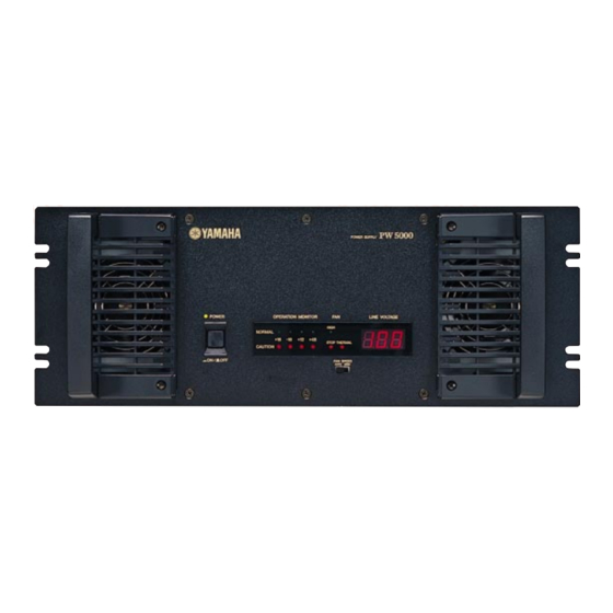
http://www.xiaoyu163.com PW5000 3 7 63 1515 0 (総合仕様) SPECIFICATIONS General Specifications U.S./Canada: 120 V, 60 Hz Power Supply Australia: 240 V, 50 Hz Other: 230 V, 50 Hz U.S./Canada: 1100 W, 1250 VA Power Consumption Other: 1100W Dimensions (W x H x D) 480 mm x 186 mm x 459 mm Weight 34 kg... - Page 4 http://www.xiaoyu163.com PW5000 3 7 63 1515 0 (パネルレイアウト) PANEL LAYOUT Front Panel (フロントパネル) POWER SUPPLY POWER OPERATION MONITOR LINE VOLTAGE HIGH NORMAL STOP THERMAL CAUTION FAN SPEED AUTO HIGH q [POWER ON/OFF] Switch ([POWER ON/OFF] スイッチ) w OPERATION MONITOR (OPERATION MONITOR) e [HIGH] Indicator ([HIGH] インジケーター)...
- Page 5 http://www.xiaoyu163.com PW5000 3 7 63 1515 0 (寸法図) DIMENSIONS L 13942296513 Units: mm (単位) u163 http://www.xiaoyu163.com...
- Page 6 http://www.xiaoyu163.com PW5000 3 7 63 1515 0 (ユニットレイアウト) CIRCUIT BOARD LAYOUT <Top view> AC 1/3 DC unit Power supply unit (電源ユニット) (DCユニット) L 13942296513 AC 3/3 AC 2/3 PN 1/2 <Left side view> <Front view> PN 1/2 PN 2/2 PN 2/2 u163 http://www.xiaoyu163.com...
- Page 7 http://www.xiaoyu163.com PW5000 3 7 63 1515 0 (分解手順) DISASSEMBLY PROCEDURE Top Cover トップカバー (所要時間:約 2 分) (Time required: About 2 minutes) [270A]のネジ 11 本を外し、トップカバーを外しま Remove the eleven (11) screws marked [270A]. The す。 (図 1) top cover can then be removed. (Fig.1) <Rear view>...
- Page 8 http://www.xiaoyu163.com PW5000 3 7 63 1515 0 Front Panel Assembly フロントパネル Ass’ y (所要時間:約 2 分) (Time required: About 2 minutes) [120]のネジ 6 本と[130]のネジ 6 本を外し、フロン Remove the six (6) screws marked [120] and the six トパネル Ass’ y を外します。 (図 1) (6) screws marked [130].
- Page 9 http://www.xiaoyu163.com PW5000 3 7 63 1515 0 Side Panel R サイドパネル R (所要時間:約 4 分) (Time required: About 4 minutes) トップカバーを外します。 (1 項参照) Remove the top cover. (See procedure 1.) [150]のネジ 8 本と[200B]のネジ 2 本を外し、マウン Remove the eight (8) screws marked [150] and the トサポートパネルと共にサイドパネル...
- Page 10 http://www.xiaoyu163.com PW5000 3 7 63 1515 0 <Front view> [40B] <Left side view> DC unit (DCユニット) DC unit (DCユニット) [40B] [40B] [40B] [40B] [60] [90] [60] [60] [40B]: Bind Head Screw (+バインド小ネジ) SP 3.0X8 MFZN2Y (EG330290) (+バインド小ネジ) [60]: Bind Head Screw SP 3.0X12 MFZN2Y (VB763800) [90]: Bind Head Tapping Screw-B...
- Page 11 http://www.xiaoyu163.com PW5000 3 7 63 1515 0 AC cable (ACケーブル) <Top view> AC 1/3 [70] [70] AC 2/3 K101 K102 AC 3/3 DS angle (DS金具) [160] [320] [160] L 13942296513 [70]: Bind Head Tapping Screw-B (+バインドBタイト) 3.0X6 MFZN2BL (EP600230) [160]: Bind Head Tapping Screw-B (+バインドBタイト)...
- Page 12 http://www.xiaoyu163.com PW5000 3 7 63 1515 0 (IC ブロック図) IC BLOCK DIAGRAM TC74HC04AP (IR000400) TC74HC08AP (IR000800) TC74HC14AP (IR001400) PW5K PN 1/2: IC307 PW5K PN 1/2: IC309,310,313,314 PW5K PN 1/2: IC312 Hex Inverter Quad 2 Input AND Hex Inverter SN74HC21N (IR002150) SN74HC563N (IR056350) SN74HC573N (IR057350) PW5K PN 1/2: IC311...
- Page 13 http://www.xiaoyu163.com PW5000 3 7 63 1515 0 CIRCUIT BOARDS (シート基板図) AC 1/3, 2/3, 3/3 Circuit Board (X2605B0) ........ 13/14 DC Circuit Board (X2607B0) ............. 15/16 PN 1/2, 2/2 Circuit Board (X2606B0) ........17/18 Note: See parts list for details of circuit board component parts. 注:シートの部品詳細はパーツリストをご参照ください。...
- Page 14 http://www.xiaoyu163.com PW5000 3 7 63 1515 0 AC 1/3 Circuit Board L 13942296513 Pattern side (パターン側) AC 2/3 Circuit Board AC 3/3 Circuit Board to Power transformer (±16V) to Power transformer (±16V) to Power transformer (±16V) to Power transformer (±16V) to DC-CN203 to DC-CN201 to DC-CN203...
-
Page 15: Nap-V994910-2
http://www.xiaoyu163.com PW5000 3 7 63 1515 0 DC Circuit Board to PN 1/2-CN306 to AC 2/3-K504 to AC 3/3-K508 to PN 1/2-CN305 to DC PARALLEL INPUT L 13942296513 to DC OUTPUT to Power transformer (±16V) to DC PARALLEL INPUT to DC OUTPUT to AC 2/3-K503 to AC 3/3-K507 u163... -
Page 16: Dc Circuit Board
http://www.xiaoyu163.com PW5000 3 7 63 1515 0 DC Circuit Board Connector assembly: WC414100 L 13942296513 Connector assembly: WC414200 u163 Pattern side (パターン側) 2NAP-V994910-2 http://www.xiaoyu163.com... - Page 17 http://www.xiaoyu163.com PW5000 3 7 63 1515 0 PN 1/2 Circuit Board to DC PARALLEL INPUT to DC-CN206 to AC 1/3-CN107 to FAN to AC 3/3-CN502 to DC OUTPUT to AC 1/3-CN112 to Power transformer to DC-CN209 to AC 1/3-CN109 to FAN (INDI) POWER ON/OFF LINE VOLTAGE...
- Page 18 http://www.xiaoyu163.com PW5000 3 7 63 1515 0 PN 1/2 Circuit Board L 13942296513 Pattern side (パターン側) PN 2/2 Circuit Board Pattern side (パターン側) u163 2NAP-V995010-2 http://www.xiaoyu163.com...
- Page 19 http://www.xiaoyu163.com PW5000 3 7 63 1515 0 INSPECTIONS Setup To make the PW5000 operation checks, setup the connector (shorting pins) shown in FIG. 1, and the voltage check connector as shown in FIG. 2. Short pin----- Connect to the DC OUTPUT (Solder terminal side) Connector (female) : VP012200 REMOTE...
-
Page 20: Dc Circuit Board
http://www.xiaoyu163.com PW5000 3 7 63 1515 0 Structure Power supply circuits ±16 volts, +12 volts, +48 volts · · Safeguard circuits · Primary power supply voltage (LINE VOLTAGE) display circuit (hereafter, listed as LV) Electrical Performance Checking operation 3-1-1 Check LV circuit operation Check that the LV is displayed simultaneous with turning the primary power on, regardless of whether the power supply switch is ON or OFF. -
Page 21: Http://Www.xiaoyu163.Com
http://www.xiaoyu163.com PW5000 3 7 63 1515 0 3-1-5 Check operation of +12 volt and +48 volt detector circuits 1. Check that about 4 ± 2 seconds after power is turned on while the power supply unit’s primary line (CN103 of AC 1/3 circuit board) is disconnected;... -
Page 22: Http://Www.xiaoyu163.Com
http://www.xiaoyu163.com PW5000 3 7 63 1515 0 検査 準備 PW5000の動作確認のため図1で示すコネクタ(ショートピン)と図2で示す電圧祖確認用のコネクタ を準備してください。 ショートピン・・・・・DC OUTPUTに接続します。 (ハンダ端子面側) コネクタ(メス):VP012200 REMOTE 3 : FG 6,11,16,21 :±16VGND 7,12,17,18 :+12VGND 8,13: REMOTE +48VGND L 13942296513 図1 電圧測定用コネクタ(測定ポイント)・・・・・DC PARALLEL INPUTに接続します。 (ハンダ端子面側) コネクタ(オス):VP012100 ±16VGND -16V +16V 1:-16V 6:±16VGND 9:+16V 18:-12VGND 19:+48V 24:+48VGND... -
Page 23: Http://Www.xiaoyu163.Com
http://www.xiaoyu163.com PW5000 3 7 63 1515 0 構成 ・± 16V、+12V、+48V 電源回路 ・プロテクション回路 ・一次電源電圧(LINE VOLTAGE)表示回路(以下 LV と記載します。 ) 電気的性能 動作確認 3-1-1 LV 回路動作確認 一次電源投入と同時に、電源スイッチの ON/OFF に関わらずに LV が表示されることを確認します。 3-1-2 無負荷動作確認 ① ショートピンは DC OUTPUT に接続しないで確認します。 ・電源スイッチを投入すると、 『POWER』LED(緑)が点灯し、FAN は回転しますが、パワーリレーの動作音は無く、 4 ± 2 秒後に『CAUTION(赤)』,『STOP(赤)』,『THERMAL(赤)』が全て(計 6ヶ)点灯することを確認します。 ②... -
Page 24: Http://Www.xiaoyu163.Com
http://www.xiaoyu163.com PW5000 3 7 63 1515 0 3-1-5 +12V、+48V 電源検出回路動作確認 1. 電源ユニットの一次線(AC 1/3 シートの CN103 )を外した状態で電源を投入すると、4 ± 2 秒後に電圧表示 LED 4 つのうち +12、+48 は『CAUTION』LED が点灯(+16、-16 は『NORMAL』LED が点灯)し、投入後 8 ± 2 秒後にシャッ トダウンし、 『CAUTION』LED 2 個(+12V,+48V)と『POWER』LED は点灯のままであることを確認します。 2. スイッチング電源の二次線 (AC 1/3 シートの CN110) を外した状態で電源を投入すると、 4 ± 2 秒後に電圧表示 LED 4つのうち... -
Page 25: Parts List
http://www.xiaoyu163.com 3 7 63 1515 0 POWER SUPPLY PARTS LIST (目次) CONTENTS (総組立) OVERALL ASSEMBLY ............2 (サブシャーシAss’ y) SUB CHASSIS ASSEMBLY ....... 6 (ボトムAss’ y) BOTTOM ASSEMBLY ........... 8 (DCユニット) DC UNIT ................ 10 (リアAss’ y) REAR ASSEMBLY ............11 (電気部品)... - Page 26 http://www.xiaoyu163.com PW5000 3 7 63 1515 0 (総組立) OVERALL ASSEMBLY Sub chassis section <Rear view> <Left side view> Sub chassis assembly: (サブシャーシAss'y) See page 6. Bottom assembly: See page 8. (ボトムAss'y) <Rear view> L 13942296513 <Front view> <Top view> Front panel section u163 http://www.xiaoyu163.com...
- Page 27 http://www.xiaoyu163.com PW5000 3 7 63 1515 0 <Rear view> Power cord <Right side view> DC unit: See page 10. Rear assembly: See page 11. <Top view> (DCユニット) (リアAss'y) L 13942296513 Accessories <Front view> u163 http://www.xiaoyu163.com...
- Page 28 http://www.xiaoyu163.com PW5000 3 7 63 1515 0 PART NO. DESCRIPTION 部 品 名 REMARKS REF NO. RANK OVERALL ASSEMBLY 総 組 立 PW5000 Power Supply Assembly 電 源 A s s ’ y (WA18100) 電 源 A s s ’ y Power Supply Assembly (WA18110) 電...
- Page 29 http://www.xiaoyu163.com PW5000 3 7 63 1515 0 PART NO. DESCRIPTION 部 品 名 REMARKS REF NO. RANK V 3 6 6 2 8 0 0 Cord Strap CS-180 コ ー ド ス ト ラ ッ プ L 13942296513 u163 : New Parts RANK: Japan only http://www.xiaoyu163.com...
- Page 30 http://www.xiaoyu163.com 3 7 6 3 1 5 1 5 0 <Top view> <Left side view> <Rear view> L 1 3 9 4 2 2 9 6 5 1 3 <Left side view> u 1 6 3...
- Page 31 http://www.xiaoyu163.com PW5000 3 7 63 1515 0 PART NO. DESCRIPTION 部 品 名 REMARKS REF NO. RANK SUB CHASSIS ASSEMBLY サ ブ シ ャ ー シ A s s ’ y PW5000 Sub Chassis Assembly サ ブ シ ャ ー シ A s s ’ y (WA18150) サ...
- Page 32 http://www.xiaoyu163.com 3 7 6 3 1 5 1 5 0 <Top view> <Front view> 60a 1/3 Power supply unit: (電源ユニット) See page 19. <Top view> <Top view> <Right sude view> L 1 3 9 4 2 2 9 6 5 1 3 Accessorise <Front view>...
- Page 33 http://www.xiaoyu163.com PW5000 3 7 63 1515 0 PART NO. DESCRIPTION 部 品 名 REMARKS REF NO. RANK BOTTOM ASSEMBLY ボ ト ム A s s ’ y PW5000 Bottom Assembly ボ ト ム A s s ’ y (WA18160) ボ ト ム A s s ’ y Bottom Assembly (WA18330) ボ...
- Page 34 http://www.xiaoyu163.com PW5000 3 7 63 1515 0 (DC ユニット) DC UNIT <Top view> <Front view> <Left side view> L 13942296513 PART NO. DESCRIPTION 部 品 名 REMARKS REF NO. QTY RANK DC UNIT D C ユ ニ ッ ト PW5000 DC Unit D...
- Page 35 http://www.xiaoyu163.com 3 7 6 3 1 5 1 5 0 <Top view> J Power code <Rear view> L 1 3 9 4 2 2 9 6 5 1 3 u 1 6 3...
- Page 36 http://www.xiaoyu163.com PW5000 3 7 63 1515 0 PART NO. DESCRIPTION 部 品 名 REMARKS REF NO. RANK REAR ASSEMBLY リ ア A s s ’ y PW5000 Rear Assembly リ ア A s s ’ y (WA18410) リ ア A s s ’ y Rear Assembly (WA18420) リ...
- Page 37 http://www.xiaoyu163.com PW5000 3 7 63 1515 0 (電気部品) ELECTRICAL PARTS PART NO. DESCRIPTION 部 品 名 REMARKS REF NO. RANK ELECTRICAL PARTS 電 気 部 品 PW5000 AAX49470 Circuit Board PW5K AC 1/3 A C 1 / 3 J シ ー ト J,U,V (V994990)(X2605B0) A...
- Page 38 http://www.xiaoyu163.com PW5000 3 7 63 1515 0 PART NO. DESCRIPTION 部 品 名 REMARKS REF NO. RANK F102 VM564000 Fuse T 8.00AL/250V S ヒ ュ ー ズ J,U,V F102 KB000790 Fuse T 4.00AL/250V S ヒ ュ ー ズ H,W,B,K,A ヒ ュ...
- Page 39 http://www.xiaoyu163.com PW5000 3 7 63 1515 0 PART NO. DESCRIPTION 部 品 名 REMARKS REF NO. RANK CN210 LB932020 Base Post Connector VH 2P TE ベ ー ス ポ ス ト CP201 WA068200 IC Protector ICP-N70 T104 I C プ ロ テ ク タ ー I...
- Page 40 http://www.xiaoyu163.com PW5000 3 7 63 1515 0 PART NO. DESCRIPTION 部 品 名 REMARKS REF NO. RANK R253 HF757220 Carbon Resistor 22.0K 1/4 J カ ー ボ ン 抵 抗 R254 HV755100 Flame Proof C. Resistor 100.0 1/4 J 不 燃 化 カ ー ボ ン 抵 抗 不...
- Page 41 http://www.xiaoyu163.com PW5000 3 7 63 1515 0 PART NO. DESCRIPTION 部 品 名 REMARKS REF NO. RANK -309 VD631600 Diode 1SS133,176,HSS104 ダ イ オ ー ド D310 VF195600 Diode 11ES4 TA1 ダ イ オ ー ド ダ イ オ ー ド...
- Page 42 http://www.xiaoyu163.com PW5000 3 7 63 1515 0 PART NO. DESCRIPTION 部 品 名 REMARKS REF NO. RANK R331 HF756470 Carbon Resistor 4.7K 1/4 J カ ー ボ ン 抵 抗 R332 VC330400 Metal Film Resistor 47.0K 1/4 F 金 属 被...
-
Page 43: Power Supply Unit
http://www.xiaoyu163.com PW5000 3 7 63 1515 0 PART NO. DESCRIPTION 部 品 名 REMARKS REF NO. RANK X3652A00 Power Transformer A (INDI) 電源トランス(INDI) X3656A00 Power Transformer UL,CSA A (INDI) 電源トランス(INDI) 電源トランス(INDI) X3659A00 Power Transformer H,B E (INDI) H,W,B,K,A 電源トランス (SUB12) X3654A00 Power Transformer A (SUB12) -
Page 44: Table Of Contents
http://www.xiaoyu163.com 3 7 63 1515 0 POWER SUPPLY UNIT ( PCU600 ) REPAIR MANUAL (目次) CONTENTS (ブロック図) BLOCK DIAGRAM ............2 FLOWCHART FOR DIAGNOSIS AND REPAIR (解析・修理フローチャート) ............3/4 (未再現試験項目) NON-REPRODUCIBLE FAILURE TESTS ....5/6 (分解手順) DISASSEMBLY PROCEDURE ..........7 L 13942296513 (付表)... -
Page 45: Block Diagram (ブロック図
http://www.xiaoyu163.com PW5000 3 7 63 1515 0 (ブロック図) BLOCK DIAGRAM PKG3 Motherboard (PKG3 マザーボード) PKG2 ︵ 入 Filter block (フィルターブロック) 力 CELL 1(AAX51970) ︶ 12.0V D/D block (12.0V D/Dブロック) PF600 (AAX51960) CELL 2(AAX51970) 12.0V D/D block PFC block (12.0V D/Dブロック) (PFCブロック)... -
Page 46: Flowchart For Diagnosis And Repair
http://www.xiaoyu163.com PW5000 3 7 63 1515 0 FLOWCHART FOR DIAGNOSIS AND REPAIR The breaker of the room is The information Refer to the decomposition procedure a trip at the time of repair. check of fault (7 pages) for how to remove. Appearance check (for any falling damages, dints, or fracture, trace of burnout, corrosion resulted from flooding, etc.) -
Page 47: 解析・修理フローチャート
http://www.xiaoyu163.com PW5000 3 7 63 1515 0 解析・修理フローチャート 修理時にその部屋の 不具合の情報確認 ※取り外し方は分解手順(7ページ)を参照 ブレーカがトリップ してください。 外観確認 (落下に伴う傷・へこみ・欠損及び焼損痕、水害による腐食等) AC電源入力 不良が発見されない場合 (OK) 出力確認 未再現試験項目実施(P6) OK? NO (NG) L 13942296513 全出力せず +48.0V 出力せず 12.0V ? ? がNG +48.0V(CELL6) PF600 (PFCブロック) ブロック交換 交換再通電 12.0V(CELL1~5) のパラ運転解除 全出力せず ?... -
Page 48: Non-Reproducible Failure Tests
http://www.xiaoyu163.com PW5000 3 7 63 1515 0 NON-REPRODUCIBLE FAILURE TESTS Printed circuit board, soldering, Visually check inside the power unit as * parts mounting, foreign materials required Verify normal output voltage for each * circuit. Check output When required, the half-fixation VR is voltage adjusted. - Page 49 http://www.xiaoyu163.com PW5000 3 7 63 1515 0 未再現試験項目 プリント基板 半田付け、部品実装、 必要に応じて電源内部の目視確認 * 異物等 * 各回路出力電圧が正常に出力されている事の 確認 出力電圧確認 必要な場合は半固定VRを調整 注1) AC入力 On/Off 動作にて出力が正常に動作 * Powe On/Off する事 Power On/Off, SW On/Off動作を行い信号送出 * 各種信号 が正常である事の確認 * オシロスコープにより出力電圧波形を観測し L 13942296513 出力リップル ながら振動加え、波形変動を確認 波形 外観確認 外観確認 *...
-
Page 50: Disassembly Procedure
http://www.xiaoyu163.com PW5000 3 7 63 1515 0 (分解手順) DISASSEMBLY PROCEDURE ショートバー Short bar (Time required: About 2 minutes) (所要時間:約 2 分) 1-1. Remove the ten (10) screws marked [A]. The two 1-1. [A]のネジ 10 本を外し、ショートバー 2 本を外しま す。 (写真 1) (2) short bars can then be removed. - Page 51 http://www.xiaoyu163.com PW5000 3 7 63 1515 0 CPU-CONT シート CPU-CONT Circuit Board (所要時間:約 4 分) (Time required: About 4 minutes) 3-1. トップカバーを外します。 (2 項参照) 3-2. 垂直方向に力を加えて、CPU-CONT シートを外し 3-1. Remove the top cover. (See procedure 2.) 3-2. Power is applied perpendicularly and a CPU-CONT ます。...
- Page 52 http://www.xiaoyu163.com PW5000 3 7 63 1515 0 PF600 PF600 (Time required: About 6 minutes) (所要時間:約 6 分) 6-1. Remove the short bar. (See procedure 1.) 6-1. ショートバーを外します。 (1 項参照) 6-2. トップカバーを外します。 (2 項参照) 6-2. Remove the top cover. (See procedure 2.) 6-3.
-
Page 53: Exhibit
http://www.xiaoyu163.com PW5000 3 7 63 1515 0 EXHIBIT Exhibit 1 12.0V D/D block check (Procedure for canceling the parallel operation) 1. Remove the short bar. (DISASSEMBLY PROCEDURE: See procedure 1) 2. Remove the top cover. (DISASSEMBLY PROCEDURE: See procedure 2) 3. - Page 54 http://www.xiaoyu163.com PW5000 3 7 63 1515 0 Exhibit 3 PCU600 SPECIFICATIONS 1) Input conditions Rated input voltage AC 100V - 240V Allowable range of input voltage AC 85-264V Input current ( * 1) 4A - 2A (max.) (AC100V - AC240V) Rated frequency 50/60Hz Allowable frequency range...
- Page 55 http://www.xiaoyu163.com PW5000 3 7 63 1515 0 付表 付表1 12.0V D/Dブロックのチェック(パラ運転解除方法) 1.ショートバーを外します。(分解手順:1項参照) 2.トップカバーを外します。(分解手順:2項参照) 3.CELL1∼CELL6を外します。(分解手順:4、5項参照) ※外したCELLを元に戻す際には、同じスロットに戻すようにしてください。 4.すべてのCELLを外した後、8個のジャンパーコネクタを外します。 L 13942296513 5.CELLを戻します。 3項の手順を逆から実施します。 6.出力電圧調整ボリュームをセンターに戻します。(CELL1∼CELL5) 付表2 不具合CELLを交換した後の再調整方法 ① ジャンパーコネクターを外したままで、交換したCELLが11∼13Vの範囲の出力であることを確認します。 ② 付表1の逆の手順で、ジャンパーコネクタを取り付けて、最後にショートバーを取り付けます。 ③ CELL 2∼5の半固定ボリュームはMAX(右回し切り)とし、CELL 1の半固定ボリュームで調整可能です。 u163 http://www.xiaoyu163.com...
- Page 56 http://www.xiaoyu163.com PW5000 3 7 63 1515 0 付表3 CPU600仕様 1) 入力条件 定格入力電圧 AC 100V-240V 入力電圧許容範囲 AC 85-264V 入力電流 ( * 1) 4A-2A (max.) (AC100V-AC240V) 定格周波数 50/60Hz 周波数許容範囲 47Hz ∼ 63Hz 突入電流 ( * 1)( * 2) 15A-35A (max.) (AC100V-AC240V) 効率 ( * 1) 70% (typ) 力率...
- Page 57 http://www.xiaoyu163.com 3 7 6 3 1 5 1 5 0 OUTSIDE DRAWING (PCU600) PW5000 Detail A-A CELL 1 CELL 2 CELL 3 CELL 4 CELL 5 CELL 6 Operation indicator (運転表示用LED) V. ADJ volume (出力電圧調整用ボリューム) "CN1" remote sensing terminal (リモートセンシング接続コネクタ) 4-M4 ...
- Page 58 http://www.xiaoyu163.com BLOCK DIAGRAM (PCU600) 3 7 6 3 1 5 1 5 0 PW5000 UCT-M210-8705-3 DF11-30DS-2DSA 2SC4304 0.01u/400 EP01C 1SS133 100k PKG1 220K 1SS133 2SC1815 330k 0.1u/50 MTZ J6.8 PKG2 220u/25 220u/25 2SC3225 AG01Y AG01Y 470p DF3-3S-2DSA (50) DF3-3S-2DSA (50) 2SC1815 470u/25 470u/25...
-
Page 59: Circuit Diagram
http://www.xiaoyu163.com 3 7 63 1515 0 POWER SUPPLY CIRCUIT DIAGRAM (目次) CONTENTS BLOCK DIAGRAM & CONNECTOR CIRCUIT DIAGRAM (ブロックダイアグラム&コネクター回路図) ......3 (回路図) CIRCUIT DIAGRAM AC 1/3 (002) ..............4 AC 2/3 (003) ..............5 AC 3/3 (003) ..............5 DC ..................6 PN 1/2 (002, 003) ............ - Page 60 http://www.xiaoyu163.com 3 7 6 3 1 5 1 5 0 PW5000 BLOCK DIAGRAM & CONNECTOR CIRCUIT DIAGRAM (PW5000) AC 1/3 AC 2/3 CN101 (3pin) Power transformer (±16V) CN202 (2pin) CN201 (3pin) CN205 (5pin) CN501 (3pin) CN204 (9pin) CN210 (2pin) CN503 (3pin) CN102 (3pin) Power transformer (±16V)
- Page 61 http://www.xiaoyu163.com AC 1/3 CIRCUIT DIAGRAM 002 (PW5000) 3 7 6 3 1 5 1 5 0 PW5000 TO SERVICE PERSONNEL Critical Components Information to PN 2/2-CN401 Components having special characteristics are marked and must be replaced with parts having specifications equal to those originally installed. T105: to Power transformer (INDI) to PN 1/2-CN302 REGULATOR +12V...
- Page 62 http://www.xiaoyu163.com 3 7 6 3 1 5 1 5 0 AC 2/3, 3/3 CIRCUIT DIAGRAM 003 (PW5000) PW5000 AC 2/3 to AC 3/3-CN503 to Power transformer to DC-CN201 (±16V) to DC-CN203 1 3 9 4 2 2 9 6 5 1 3 AC 3/3 to Power transformer to DC-CN201...
- Page 63 http://www.xiaoyu163.com DC CIRCUIT DIAGRAM (PW5000) 3 7 6 3 1 5 1 5 0 PW5000 to AC 3/3-K507 to DC OUTPUT +16V OUTPUT to DC OUTPUT -16V OUTPUT -16V OUTPUT 16V adj. OP AMP +16V OUTPUT Low adj. OP AMP to PN 1/2-CN305 1 3 9 4 2 2 9 6 5 1 3 to Power transformer...
- Page 64 http://www.xiaoyu163.com 3 7 6 3 1 5 1 5 0 PN 1/2, 2/2 CIRCUIT DIAGRAM 002 (PW5000) PW5000 PN 1/2 REGULATOR -5V REGULATOR +5V to Power transformer (INDI) LINE VOLTAGE 1 3 9 4 2 2 9 6 5 1 3 to AC 1/3-CN107 TO SERVICE PERSONNEL Critical Components Information...
- Page 65 http://www.xiaoyu163.com PN 1/2 CIRCUIT DIAGRAM 003 (PW5000) 3 7 6 3 1 5 1 5 0 PW5000 INVERTER to FAN INVERTER to FAN INVERTER to AC 1/3-CN109 to DC OUTPUT to DC-CN209 to DC PARALLEL INPUT +16VTr ALARM INVERTER to DC-CN206 -16VTr ALARM +16V OUTPUT ALARM -16V OUTPUT ALARM...