Panasonic aj-spd850p Operating Instructions Manual
Memory card recorder
Hide thumbs
Also See for aj-spd850p:
- Parts list (14 pages) ,
- Menu information (24 pages) ,
- Operating instructions manual (80 pages)

Related Manuals for Panasonic aj-spd850p


Summary of Contents for Panasonic aj-spd850p
- Page 1 Operating Instructions Memory Card Recorder Model No. Before operating this product, please read the instructions carefully and save this manual for future use. ENGLISH...
- Page 2 For AJ-SPD850P IMPORTANT “Unauthorized recording of copyrighted television programmes, video tapes and other materials may infringe the right of copyright owners and be contrary to copyright laws.” THIS APPARATUS MUST BE GROUNDED To ensure safe operation the three-pin plug must be inserted only into a standard three-pin power outlet which is effectively grounded through normal household wiring.
- Page 3 Operation at a voltage other than 120 V AC may require the use of a different AC plug. Please contact Notice (U.S.A. only): either a local or foreign Panasonic authorized service center for assistance in selecting an alternate AC This product has a fluorescent lamp that contains plug.
- Page 4 If you lose the fuse cover the plug must not be used until a replacement cover is obtained. Fuse A replacement fuse cover can be purchased from your local Panasonic Dealer. indicates safety information. – 4 –...
- Page 5 For AJ-SPD850E IMPORTANT “Unauthorized recording of copyrighted television programmes, video tapes and other materials may infringe the right of copyright owners and be contrary to copyright laws.” Operating precaution Operation near any appliance which generates strong magnetic fields may give rise to noise in the video and audio signals.
-
Page 6: Table Of Contents
Setup (Initial settings)........34 text.) Setup menus...........35 To obtain the source codes, go to the following home • SYSTEM menu ..........37 page:http://panasonic.biz./sav/ • USER menus ...........38 The manufacturer asks users to refrain from directing <BASIC> .............38 inquiries concerning the source codes they have <OPERATION>...........42... -
Page 7: Introduction
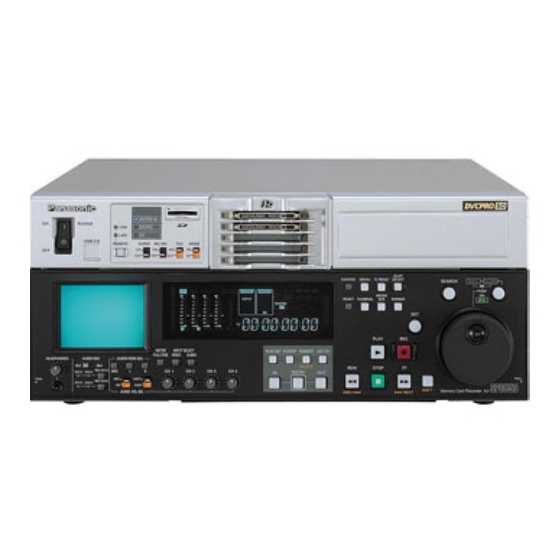
Introduction The AJ-SPD850 is a memory card recorder that has five You can also select and play parts of the video and audio slots for cards (such as the AJ-P2C002SG which is sold recorded on cards in the memory card recorder, in an order separately) that conform to the PC card type II standard. -
Page 8: Features
Features Recording and play of files on memory cards Multifunctional interface The memory card recorder can record to and play video • Analog video input/output and audio on memory cards (such as the AJ-P2C002SG Both composite and component signal inputs/outputs which is sold separately;... -
Page 9: Control Reference Guide
Control reference guide Front panel — Upper section DVCPRO 50 POWER DVCPRO USB 2.0 REMOTE SUPER REC INH MODE SLOT COUNTER MENU TC PRESET SELECT SEARCH SHTL SLOW PUSH MENU RESET THUMBNAIL MARKER PLAY METER INPUT SELECT PLAY LIST EVENT INSERT GO TO FULL/FINE VIDEO... - Page 10 Control reference guide (continued) Front panel DVCPRO 50 POWER — Under section (1/3) DVCPRO USB 2.0 REMOTE SUPER REC INH MODE SLOT COUNTER MENU TC PRESET SELECT SEARCH SHTL SLOW PUSH MENU RESET THUMBNAIL MARKER PLAY METER INPUT SELECT PLAY LIST EVENT INSERT GO TO FULL/FINE VIDEO...
- Page 11 Control reference guide (continued) Front panel — Under section (2/3) SLOT COUNTER MENU TC PRESET SELECT SEARCH SHTL SLOW PUSH MENU RESET THUMBNAIL MARKER PLAY METER INPUT SELECT PLAY LIST EVENT INSERT GO TO FULL/FINE VIDEO AUDIO HEADPHONES AUDIO MIX AUDIO MON SEL 1&2 3&4...
- Page 12 Control reference guide (continued) Front panel — Under section (3/3) SLOT COUNTER MENU TC PRESET SELECT SEARCH SHTL SLOW PUSH MENU RESET THUMBNAIL MARKER PLAY METER INPUT SELECT PLAY LIST EVENT INSERT GO TO FULL/FINE VIDEO AUDIO HEADPHONES AUDIO MIX AUDIO MON SEL 1&2 3&4...
- Page 13 Control reference guide (continued) When the AUDIO MIX switch is at the [3&4] CHROMA LEVEL dial and switch setting, the setting is switched by one step in the When ENC CONTROL is set to [LOCAL], you can adjust sequence of A → → B → → C each time the REC CH2/4 the chroma level.
-
Page 14: Display
Use the METER selector button to switch the audio level synchronized signal (REF VIDEO) is inside the display between FULL and FINE mode (See page 13). prescribed range. For AJ-SPD850P For AJ-SPD850E At all other times, the lamp is off. FULL mode... -
Page 15: Rear Panel
Control reference guide (continued) Rear Panel (1/2) AES/EBU ANALOG REMOTO ANALOG VIDEO CH1•2 AUDIO AC IN REMOTO IN 75Ω CH3•4 ACTIVE THROUGH REF VIDEO CH1•2 ENCODER REMOTE 75Ω CH3•4 AUDIO (SUPER) RS-232C DVCPRO/ (OPTION) 100BASE-TX (SUPER) SIGNAL SERVICE ONLY AC IN socket ANALOG AUDIO IN connectors Connect one end of the power cord supplied to this These are the analog audio input connectors. - Page 16 Control reference guide (continued) Rear Panel (2/2) AES/EBU ANALOG REMOTO ANALOG VIDEO CH1•2 AUDIO AC IN REMOTO IN 75Ω CH3•4 ACTIVE THROUGH REF VIDEO CH1•2 ENCODER REMOTE 75Ω CH3•4 AUDIO (SUPER) RS-232C DVCPRO/ (OPTION) 100BASE-TX (SUPER) SIGNAL SERVICE ONLY Cool the memory card recorder. If the fan stops, “E-10”...
-
Page 17: Recording And Playing
Recording and playing Inserting P2 cards Removing P2 cards Note: Do not remove a P2 card while it is being accessed or while Before using the unit for the first time, be absolutely sure it is being recognized after it has been inserted (while its to set the internal clock using setup menu item No.069 corresponding access LED is flashing orange). -
Page 18: Protecting Against A Possible Erasure
Recording and playing (continued) Protecting against a possible erasure P2 card access LEDs and P2 card status Switch the write-protect switch of the P2 card to P2 card [PROTECT]. P2 card status access LED Note: Green lighting Recording and play are possible. Any attempt to change the position of the write-protect Recording and play are possible. -
Page 19: Connections
Connections Example of the memory card recorder and DVCPRO VTR Source machine: Set the CONTROL switch on the front panel to [REMOTE] (the memory card recorder : AJ-SPD850). Recorder: Set the CONTROL switch on the front panel to [LOCAL] (VTR : AJ-SD955 or others). Reference signal generator Remote control signal (9 pin) -
Page 20: Jog/Shuttle (Search Dial)
Jog/Shuttle (Search dial) Locate the edit points. Each time it is pressed, it is set alternatively to the SHTL/SLOW mode or the JOG mode, and the JOG, SHTL or SLOW lamp lights. When the power is turned on, the search dial will not operate unless it is first returned to the STILL position. Jog mode Shuttle mode/Slow mode (1) Press the search dial so that it remains... -
Page 21: Graphic User Interface (Gui)
Graphic User Interface (GUI) Working with clip thumbnails A clip is a piece of data containing video and audio from a single video recording, as well as additional information such as voice memos and meta-data. The memory card recorder allows the user to perform the following operations using the search dial, SHIFT button, and SET button while viewing the clip thumbnails shown on the LCD. - Page 22 Graphic User Interface (GUI) (continued) Thumbnail screen Press the THUMBNAIL button to display the thumbnail screen on the LCD. Press the THUMBNAIL button again to return to the normal display. Press the MENU BAR button on the thumbnail screen to change the pointer to a menu bar.
- Page 23 Graphic User Interface (GUI) (continued) Menu bar Playing clips (1) Press the THUMBNAIL button. The menu bar contains menu items for performing clip operations, switching/setting the thumbnail display, etc. The thumbnail screen is displayed on the LCD. To use the menu bar, press the MENU BAR button on (2) Use the search dial to move the pointer to the the thumbnail screen.
- Page 24 Graphic User Interface (GUI) (continued) Switching the thumbnail display Shot marks It is possible to switch the thumbnail screen so that only The memory card recorder allows the user to add shot clips meeting certain conditions are displayed. marks to clip thumbnails in order to distinguish clips from (1) Press the THUMBNAIL button.
- Page 25 Graphic User Interface (GUI) (continued) (5) Use the search dial to move the pointer to the Voice memos still image associated with the voice memo you A voice memo is audio data which is separate from the original recorded audio and can be added to a clip want to play, and then press the SET button.
- Page 26 Graphic User Interface (GUI) (continued) Deleting clips Formatting a P2 card (1) Press the THUMBNAIL button. (1) Press the THUMBNAIL button. The thumbnail screen is displayed on the LCD. The thumbnail screen is displayed on the LCD. (2) Use the search dial, FF button or REW button (2) Press the MENU BAR button.
- Page 27 Graphic User Interface (GUI) (continued) Thumbnail display settings Network settings Thumbnail display options can be customized as suitable Perform the network settings. for the intended use. (1) Press the THUMBNAIL button. (1) Press the THUMBNAIL button. The thumbnail screen is displayed on the LCD. The thumbnail screen is displayed on the LCD.
- Page 28 Graphic User Interface (GUI) (continued) SHOOT: Displaying the clip properties [SHOOTER], [START DATE], [END DATE], From the menu bar, select [PROPERTY], then [CLIP [LOCATION]: Information on the altitude, longitude, PROPERTY]. latitude, source, place name, recording start date, The following screen is displayed. recording end date, etc.
-
Page 29: Play List
Play List The play list function enables only particular parts of the Switch and submenu selections images and sound recorded on five P2 cards to be selected and the selected parts to be played in any order using only Play list buttons the unit by operating the IN, OUT and ENTRY buttons on the front panel. - Page 30 The configuration of [SETTING] [OPERATION] on the menu bar is as follows. [SETTING] [REPLACE TC] [REPLACE] [ON] [OFF] [START TC] [TC] [START TC: [DF] [DF] [NDF] For AJ-SPD850P [OPERATION] [DELETE ALL] [NO] [YES] [IMPORT] [MEMORY] [SLOT1] [SLOT5] [SD CARD] [EXIT] [SELECTED CLIP]...
- Page 31 Play List (continued) Flow of operations in creating a play list (registering an event) Creating a play list Registering events (1) Press the PLAYLIST button in the stop mode to switch to the play list screen. (2) Move to the event number corresponding to the event you want to register.
- Page 32 Play List (continued) Changing events Moving events On the play list screen, move the pointer to the number of This button is used to change the sequence of events in the event to be changed, and press the EVENT button to the play list.
- Page 33 [REPLACE TC] → [START TC] → [TC] → [START [SD CARD]: The play list data stored on the SD memory card is selected. For AJ-SPD850P: [SELECTED CLIPS]: The clips selected on the thumbnail • Set [DF] or [NDF] for TC. screen are turned into play list Select [START TC] →...
-
Page 34: Setup (Initial Settings)
Setup (Initial settings) The memory card recorder’s main settings are performed while making selections using a system of menus. If a TV monitor has been connected to the VIDEO OUT 3 connector or SDI OUT 3 connector (optional) on the rear panel and the SUPER switch is set to [ON], the setting menus are displayed on the TV monitor. -
Page 35: Setup Menus
Setup menus The memory card recorder can hold five user files, each of Setting and releasing the lock mode which has its own specific menu settings, and one of these The lock mode can be set to protect the system file and files can be selected for use. - Page 36 Setup menus (continued) Loading user files Saving user files The contents of the USER2, USER3, USER4 or USER5 (1) Press the MENU button file can be copied (loaded) into the USER1 file. Also, the (2) Press the REW button or FF button while contents of the USER1 file can be copied (saved) into the holding down the DIAG button to select the USER2, USER3, USER4 or USER5 file.
-
Page 37: System Menu
Setup menus (continued) SYSTEM menu No./Item Description No./Item Description Coarse adjustment of system phase: 90 ° units This adjusts the audio output phase with respect to the video output: 20.8 µs steps SYS SC COAR. Note: 0000 AV PHASE –: The audio output phase is advanced If setting operation is 0001 with respect to the video output. -
Page 38: User Menus
Setup menus (continued) SYSTEM menu USER menu <BASIC> No./Item Description No./Item Description This sets the preroll time. This adjusts the brightness of the The preroll time can be set from 0 to 15 LCD monitor on the front panel. P-ROLL TIME seconds in 1-second increments. - Page 39 Setup menus (continued) USER menu <BASIC> No./Item Description No./Item Description This selects what information is to be This sets the position of the characters provided by the time code and other on the horizontal plane for the time DISPLAY SEL superimposed displays output from code and other superimposed displays CHARA H-POS...
- Page 40 Setup menus (continued) USER menu <BASIC> No./Item Description No./Item Description This sets the memory card recorder’s Sets the internal clock time. recording and playback format. SYS FORMAT CLOCK SET Note: 0000 50M : Press the STOP button to display a sub- DVCPRO50 (50 Mbps) is selected.
- Page 41 USER menu <BASIC> No./Item Description No./Item Description This selects the TV system. Sets the time difference from the world standard time. [525i system] [625i system] TV SYSTEM TIME ZONE 0000 0000 0000 00:00 0001 0001 0001 +00:30 0002 +01:00 0000: 0050 –00:30 The 525 interlace/59.94 Hz system is...
-
Page 42: Operation
Setup menus (continued) USER menu <OPERATION> No./Item Description No./Item Description This selects the memory card This selects the direct search dial operation. recorder mode in which the EE status is established when the MODE switch SEARCH ENA AUTO EE SEL 0000 DIAL : is set to EE. - Page 43 Setup menus (continued) USER menu <OPERATION> No./Item Description No./Item Description This selects the EE mode output This selects whether audio input signals. switching using the INPUT SELECT EE MODE SEL A IN SEL INH button is to be enabled or disabled. 0000 NORMAL : Signals are output with a delay 0000 OFF :...
-
Page 44: Interface
Setup menus (continued) USER menu <INTERFACE> No./Item Description No./Item Description These settings are for selecting the This selects whether the REMOTE none, odd or even for the RS-232C (9P) connector functions when the PARITY parity bit. 9P SEL REMOTE button is lit. 0000 NON : 0000 OFF : Parity bit is not used. -
Page 45: Edit
Setup menus (continued) USER menu <EDIT> No./Item Description No./Item Description This selects the mode after cue-up This selects STD or NON-STD in operation is complete. accordance with the composite input AFTER STD/NON-STD signal. CUE-UP 0000 STOP : STOP mode 0001 STILL : SHTL STILL mode 0000 AUTO : Standard/non-standard signals are... -
Page 46: Time Code
Setup menus (continued) USER menu <TIME CODE> No./Item Description No./Item Description This selects the time code to be used This selects whether to output the when an external time code is to be VITC signal at the positions selected EXT TC SEL used. -
Page 47: Video
Setup menus (continued) USER menu <TIME CODE> USER menu <VIDEO> No./Item Description No./Item Description This is used to switch the phase of This selects the internal signal. the time code, which is output from TC OUT REF the TIME CODE OUT connector, for INT SG 0001 BB :... - Page 48 Setup menus (continued) USER menu <VIDEO> No./Item Description No./Item Description This selects the operation mode for This selects whether to superimpose edge subcarrier reduction (ESR) in EDH onto the SDI output signals. ESR MODE the playback circuit. 0000 OFF : EDH is not superimposed. 0001 ON : EDH is superimposed.
- Page 49 SETUP 25 in the DVCPRO (25 Mbps) mode. SETUP 50 in the DVCPRO50 (50 Mbps) mode. (For AJ-SPD850P) When the STOP button is pressed, (For AJ-SPD850P) When the STOP button is pressed, operation is transferred to the sub-...
-
Page 50: Audio
Setup menus (continued) USER menu <VIDEO> USER menu <AUDIO> No./Item Description No./Item Description This selects whether or not to record This selects the audio input (CH1) the UMID information on the card. reference level switching. UMID REC CH1 IN LV 0000 OFF : 0000... - Page 51 Setup menus (continued) USER menu <AUDIO> No./Item Description No./Item Description This selects the audio monitor output This selects the CH1 and CH2 digital (Lch) reference level switching. input when USER SET has been selected MONIL OUT D IN SEL12 by pressing the memory card recorder’s 0000 AUDIO INPUT SELECT button.
-
Page 52: Blank
Setup menus (continued) USER menu <V BLANK> No./Item Description No./Item Description Used to select the number of AUDIO Sub-screen channels for DVCPRO (25 Mbps) or This selects the additional line where 25M REC DV (25 Mbps) recording. the signals are to be recorded. REC LINE1 0000 2CH:... - Page 53 Setup menus (continued) USER menu <V BLANK> No./Item Description No./Item Description This selects the mode for recording This selects the additional line where signals on additional lines. the signals are to be recorded. ADD LINE 50 REC LINE3 0000 OFF : [525i system] [625i system] No signals are recorded on additional lines.
- Page 54 Blanking is forcibly effected. 0000 MOJI : MOJI system 0001 THRU : No blanking is effected. LINE 10&273 (For AJ-SPD850P) 0001 NABTS : NABTS system Notes: • This menu option is not displayed in the LINE 21&284 625i system. • VITC signals are often mistakenly...
- Page 55 Setup menus (continued) USER menu <V BLANK> Number of lines which can be set for TELETEXT No./Item Description This selects the method used to • When 25 Mbps is the recording/playback format. detect the lines in which the teletext Number of lines which can be set signals are to be recorded.
-
Page 56: Menu
Setup menus (continued) USER menu <MENU> No./Item Description No./Item Description This selects the user file whose This loads the contents of the contents will be loaded into USER1. selected user file into USER1 and it LOAD P. ON LOAD starts operation with the USER1 0000 USER2 : settings when the power is turned on. -
Page 57: Time Code/User Bit
Time code/user bit Time code Setting the external time code The time code is used when the time code signal generated (1) Set the memory card recorder to stop mode by the time code generator (time code signal generator) is to (2) Select “TC”... -
Page 58: Superimpose Screen
Superimpose screen The control signals, time code, etc. are displayed using Characters displayed abbreviations. The background of characters superimposed on the display can be changed using setup menu No. 011 (CHARA TYPE). TV monitor TV monitor TV monitor Abbreviations: CTL : Control signal count value Display position TCR : Time code data recorded in the SBC area The position of the characters superimposed on the display... -
Page 59: Video Output Signals And Servo Reference Signal
Video output signals and servo reference signal This section explains how the output signals and servo Notes: reference signal are selected. Synchronization is determined as follows depending on the availability of the REF VIDEO input signal when External synchronization of video output signals “BB”, “CB100”... -
Page 60: Audio V Fade Function
Audio V fade function When editing cards, the edit point splicing selection (setup menu No. 727: PB FADE) information is recorded on the card. This information is then sensed during playback, etc., and V fade or cut processing is automatically performed for these sections. -
Page 61: Audio Recording Channel And Monitor Output Selection
Audio recording channel and monitor output selection Audio recording channel Monitor output channel The audio is selected as shown below by using the The monitor output channels are selected using the AUDIO MIX switch, REC CH1/CH3 and REC CH2/CH4 MONITOR SELECT and MONITOR MIX button as shown buttons on the front panel. -
Page 62: Rack Mounting
For the installation rails, it is recommended that the 18-inch rail and bracket (model number CC3061-99-0400) by Chassis Trak be used. (The complete slide rail and bracket deck is not available from Panasonic.) For further details, consult your dealer. (1) Attach the inner members of the slide rails Refer to the figure below for the locations where the screws are to be attached. -
Page 63: Condensation
Condensation Condensation occurs due to the same principle involved When moving the deck to locations such as these, leave it when droplets of water form on a window pane of a heated standing for about 10 minutes rather than switching on the room. -
Page 64: Error Messages
Error messages When a warning occurs in this unit, the error number is Displaying the DIAG menu indicated on the counter display. (1) Press the DIAG button. Open the DIAG menu to display a description of the error on The DIAG menu screen is displayed on the monitor, and the counter display or monitor TV. - Page 65 Error messages (continued) “WARNING” information display • A warning message is displayed whenever a warning occurs. When warnings have not been detected, “NO WARNING” is displayed. • When multiple warning occur, the descriptions for each warning can be checked by turning the search dial. If “T&S&M”...
- Page 66 Error messages (continued) If “E- ” lights up in the monitor display, the contents are displayed when the DIAG-MENU is opened. Monitor display Priority Description Deck operation Message Displayed when trouble has occurred in the video or audio during high E-21 REC WARNING recording.
-
Page 67: Rs-232C Interface
RS-232C interface The memory card recorder can be operated by commands Software specifications (Protocol) when the RS-232C interface is used. Communication parameters (See command table on pages 68, 69.) Communication Asynchronous, full duplex system Conditions for acknowledging commands Communication 300/600/1200/2400/4800/9600 from RS-232C interface speed •... - Page 68 RS-232C interface (continued) Return format Deck Return (completion) Send command → [memory card recorder controller (PC)] operation message The following responses are made to the command. If ↔ ↔ REWIND [STX] ORW [ETX] [STX] ORW [ETX] necessary, more than one response is made. This command is for rewinding.
- Page 69 RS-232C interface (continued) Commands relating to inquiries Notes: • As for the return (completion) message, [ACK] is first returned when data is received, and the execution message is subsequently returned. It is only the execution message which is listed in this table.
-
Page 70: Connector Signals
Connector signals VIDEO IN RS-422A REMOTE (9P) × × (REMOTE) SDI IN 2, Active through (DIGITAL) (Board, option) Pin No. Signal × × Y, PB, PR FRAME GROUND (ANALOG) (Board, option) TRANSMIT A × × 2, Loop-through, RECEIVE B VIDEO IN 75 Ω... -
Page 71: Specifications
Specifications GENERAL Component IN/component OUT Video bandwidth: For AJ-SPD850P Power supply: AC 100 – 240 V, 50 / 60 Hz : 30 Hz to 5.75 MHz (-2.0 dB) Power consumption: 80 W, 105 W (with all options) PB/PR : 30 Hz to 2.75 MHz (-2.0 dB) For AJ-SPD850E indicates safety information. - Page 72 Less than 0.05% (1 kHz, emphasis OFF, reference level) Crosstalk: Less than –80 dB (1 kHz, between 2 channels) Headroom: For AJ-SPD850P: 20 dB For AJ-SPD850E: 18 dB De-emphasis: T1 = 50 µsec, T2 = 15 µsec (auto on/off) Audio Input Connector Analog input (CH1, CH2, CH3, CH4): XLR x 4, 600 Ω/high impedance selectable (factory...
- Page 73 PANASONIC BROADCAST & TELEVISION SYSTEMS COMPANY UNIT COMPANY OF MATSUSHITA ELECTRIC CORPORATION OF AMERICA Executive Office: One Panasonic Way 4E-7, Secaucus, NJ 07094 (201) 348-7000 EASTERN ZONE: One Panasonic Way 4E-7, Secaucus, NJ 07094 (201) 348-7621 Southeast Region: 1225 Northbrook Parkway, Ste 1-160, Suwanee, GA 30024 (770) 338-6835...