Panasonic AJ-HPM100P Operating Instructions Manual
P2hd memory card portable recorder/player
Hide thumbs
Also See for AJ-HPM100P:
- Mechanical parts list (9 pages) ,
- Operating instructions manual (130 pages)
Table of Contents
Advertisement
Quick Links
DEUTSCH
Für Erlauterungen in Deutsch, konsultieren Sie bitte die mitgelieferte CD-ROM.
FRANÇAIS
Pour des explications en français, veuillez vous reporter au CD-ROM fourni.
ITALIANO
Per le istruzioni in italiano, vedere il CD-ROM in dotazione.
ESPAÑOL
Para la explicación en español, consulte el CD-ROM uministrado.
Before operating this product, please read the instructions carefully and save this manual for future use.
• AVC-Intra capability is available when the optional AVC-Intra Codec board AJ-YBX200G is installed to the unit.
S1106S2077 -P
D
Printed in Japan
Memory Card Portable Recorder/Player
Operating Instructions
AJ-HPM100P
Model No.
AJ-HPM100E
Model No.
ENGLISH
VQT1B57-2
Advertisement
Table of Contents

Related Manuals for Panasonic AJ-HPM100P


Summary of Contents for Panasonic AJ-HPM100P
-
Page 1: Operating Instructions
Before operating this product, please read the instructions carefully and save this manual for future use. • AVC-Intra capability is available when the optional AVC-Intra Codec board AJ-YBX200G is installed to the unit. S1106S2077 -P Printed in Japan Operating Instructions AJ-HPM100P Model No. AJ-HPM100E Model No. ENGLISH... -
Page 2: Read This First
U.S.A. and Canada. CAUTION: Operation at a voltage other than 120 V AC may require the use of a different AC plug. Please contact either a local or foreign Panasonic authorized service center for assistance in selecting an alternate AC plug. -
Page 3: Important Safety Instructions
Read this first! For AJ-HPM100P IMPORTANT SAFETY INSTRUCTIONS 1) Read these instructions. 2) Keep these instructions. 3) Heed all warnings. 4) Follow all instructions. 5) Do not use this apparatus near water. 6) Clean only with dry cloth. 7) Do not block any ventilation openings. Install in accordance with the manufacturer’s instructions. - Page 4 Responsible Party: Panasonic Corporation of North America One Panasonic Way, Secaucus, NJ07094 Support contact: Panasonic Broadcast & Television Systems Company 1-800-524-1448 This device complies with Part 15 of FCC Rules. Operation is subject to the following two conditions: (1)This device may not cause harmful interference, and (2) this device must accept any interference received, including interference that may cause undesired operation.
-
Page 5: Caution For Ac Mains Lead
If you lose the fuse cover the plug must not be used until a replacement cover is obtained. A replacement fuse cover can be purchased from your local Panasonic Dealer. indicates safety information. FOR U.K. ONLY How to replace the fuse 1.Open the fuse compartment with a screwdriver. - Page 6 Read this first! For AJ-HPM100E ■ THIS EQUIPMENT MUST BE EARTHED To ensure safe operation, the three-pin plug must be inserted only into a standard three-pin power point which is effectively earthed through normal household wiring. Extension cords used with the equipment must have three cores and be correctly wired to provide connection to the earth.
-
Page 7: Table Of Contents
Contents Introduction Clip Management Included Accessories ... 11 Optional Accessories ...12 Opening and Closing the Top Panel ... 13 Features ... 14 Control Reference Guide ... 17 Audio and Video Controller ...17 GUI Operations ...20 Panel Control Unit and Card Slots ...23 LCD Panel ...24 Rear Panel ...25 Side Panel ...28... - Page 8 Using Play List Preparing a Metadata Upload File ...52 Setup to Attach Metadata ...52 Loading Set Metadata Values ...54 Recording Clips Containing Metadata ...55 Formatting P2 Cards ... 57 Checking Card Status ... 58 Selecting Information to Display ...58 Displaying Card Status Information ...59 Play List Function ...
- Page 9 Using USB Connectors and SD/SDHC Memory Cards Setup Indicating Event Property ...91 Event Review ...92 Playing Back Play Lists ... 93 Setting the Playback Time Code (TC) ...93 Playing Back the Play List ...94 Creating New Clips From the Play List (Edit Copy) ... 95 Using USB Connectors ...
- Page 10 For Long and Trouble-Free Operation Condensation ... 137 Maintenance ... 137 Error Messages ... 138 WARNING information display ...139 “HOURS METER” information display ...144 List of Shortcuts ...145 Updating the Firmware in This Unit ... 147 Handling P2 Card Recording ... 148 Specifications ...
-
Page 11: Included Accessories
■ Panasonic makes no guarantees for your recordings Please understand that Panasonic makes no guarantees for your recordings in cases where images and/or sound were not re- corded as you intended due to problems with this unit or P2 cards. -
Page 12: Optional Accessories
Optional Accessories • AVC-Intra Codec board AJ-YBX200G ◆ NOTE: • Do not use optional boards other than the above product. Included Accessories... -
Page 13: Opening And Closing The Top Panel
Opening and Closing the Top Panel ◆NOTE • Take care to avoid pinching your fingers when opening and closing the top panel. • Check that the card lock is set to on before closing the top panel. Be sure to set the card lock to on before closing the top panel. -
Page 14: Introduction
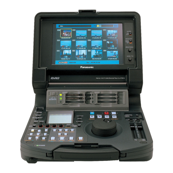
Introduction Features The AJ-HPM100 is a portable memory card recorder/player equipped with six P2 card (*) slots and a 9-inch color LCD monitor. Capability to record and play back audio and video in the compressed DVCPRO HD, DVCPRO50, DVCPRO/DV and AVC-Intra (option) formats on six P2 cards (*) allows you to use the unit like a conventional editing VTR player. - Page 15 ■ Connecting a P2 Card Camera A P2 card recorded in a P2 camera recorder plugs directly into a PC card slot for immediate access. The P2 card is a semiconductor memory card that Panasonic developed for professional AV use. <About P2 cards>...
- Page 16 ■ AVC-Intra Codec Option Supported The addition of an optional AVC-Intra Codec board AJ- YBX200G will enable use of the AVC-Intra Codec. Introduction: Features...
-
Page 17: Control Reference Guide
Control Reference Guide Audio and Video Controller Headphones connector POWER switch Turns the power on and off. METER (FULL/FINE) selector button Switches the scale of the audio level meter. FULL mode: Selects the standard scale (– ∞ to 0 dB range) FINE mode: Selects a scale divided into 0.5 dB increments. - Page 18 METER SELECT switch Switches to CH1-4 or CH5-8 in the audio meter and the monitor. INPUT SELECT buttons Switch between video and audio input signals. You can also switch the input signals to internal signals selected in setup menu No. 601 (VIDEO INT SG). VIDEO: Each press of the VIDEO button switches the input video signal in the following...
- Page 19 mode to check EE mode video and audio on the monitor (EE mode is not available during IEEE1394 input). Press the STOP button to return to the original video and audio. REW/PREV button Press to rewind. Select the speed in setup menu No. 102 (FF.
-
Page 20: Gui Operations
GUI Operations PLAY LIST button Press to create play lists or to play a created play list. The PLAY LIST button lights and the play list screen appears on LCD panel or on a monitor output image. Press again to exit the play list screen. The PLAY LIST button goes off. - Page 21 MENU/DIAG button MENU button Press this button to open the MENU. Press again to return to the previous screen. DIAG (SHIFT+MENU) button Press to show information about this unit. Press again to return to the previous screen. However, this function is not available while thumbnails or play lists are displayed.
- Page 22 GO TO/MOVE button Use this button to move the IN, OUT, or SPLIT point of events registered in a play list. It can also be used for CUE UP when the THUMBNAIL and PLAY LIST buttons are off. Hold down the IN/OUT button and press the GO TO button to move and cue up to the IN and OUT points.
-
Page 23: Panel Control Unit And Card Slots
Panel Control Unit and Card Slots OFF ON CARD LOCK 9-inch Color LCD Monitor Thumbnail screens facilitate video searches and checks. Card Lock This lever locks the cards in place when the top panel is closed. Set the lever to ON before closing the top panel. -
Page 24: Lcd Panel
LCD Panel Level meter Indicates the level of audio signals for CH1, CH2, CH3 and CH4. The input signal level of audio signals is indicated during recording and when EE is selected. During playback the meter indicates output signal levels. Use the METER selector button to switch the audio level display to FULL mode or FINE mode. -
Page 25: Rear Panel
Rear Panel SERIAL DIGITAL COMPONENT AUDIO and VIDEO IN/OUT connectors These connectors enable input and output of serial digital component audio and video signals. ◆ NOTE: • The input digital audio signals must be synchronized with the video input signals. Otherwise, the audio signals will be affected by noise. - Page 26 DC IN socket Connect a 12 V DC power supply here. Use an external 12 V DC, 4.3 A (15 A peak or more) DC power supply. When the voltage goes below approx. 10.6 V, the power supply of this unit shuts down (when menu No. 180 BATTERY SEL is not “TYPE-A”...
-
Page 27: Basic Setup
ANALOG COMPOSITE VIDEO IN connector Inputs analog composite video signals. ANALOG COMPONENT VIDEO OUT connectors Inputs analog composite video signals during output of HD signals. When SD is selected as the output signal, three composite signals are output. Setup menu 643 OUT MODE SEL determines the signals that are output. -
Page 28: Side Panel
• For the latest information not available in the Operating Instructions, visit the P2 support desk at the following Web sites. For English: https://eww.pavc.panasonic.co.jp/pro-av/ • The term “SD memory card” will be used below as a generic for SD and SDHC memory cards. -
Page 29: Moving Between Screens And Menu Operations
Moving Between Screens and Menu Operations Operating Modes This unit provide the three operating modes described below. Use the THUMBNAIL and PLAY LIST buttons to select these modes. Lamps indicate which mode is currently engaged. Recording and playback modes THUMBNAIL PLAY LIST TCR 00 : 00 : 20 : 29 Event register/edit modes... -
Page 30: Menu Operations
Menu Operations Press the MENU button in each mode to open the menu. Perform menu operations as described below. Introduction: Moving Between Screens and Menu Operations Press the MENU button to open the menu. Use the cursor buttons to place the cursor on menu items. -
Page 31: Using The On-Screen Keyboard
Using the On-screen Keyboard Using the Full Keyboard The full keyboard appears when necessary. Move the cursor to the character you want to enter and press the SET button. Use the cursor buttons to move the cursor. The keyboard keys have the functions listed below. Function Deletes one character Caps... -
Page 32: Recording, Playback And P2 Card Handling
Recording, Playback and P2 Card Handling Insert a P2 Card ◆ NOTE: • When you use this unit for the first time, be sure to set the internal clock in setup menu No. 069 (CLOCK SET). Turn on the POWER switch of this unit. Insert a P2 card in a P2 card slot, and push it in until the EJECT button pops out. -
Page 33: Removing P2 Cards
Removing P2 Cards ◆ NOTE: • Do not remove P2 cards during access or during recognition directly after insertion (when the P2 card access LED flashes orange). Press the STOP button. When the P2 card access LED of a card to be removed flashes orange, press the STOP button to stop the flashing. - Page 34 For the latest information on P2 cards and SD memory cards For the latest information not available in the Operating Instructions of P2 cards and SD memory cards, visit the P2 support desk at the following Web sites. For English: https://eww.pavc.panasonic.co.jp/pro-av/...
-
Page 35: Jog And Shuttle Operations Using The Search Dial
Jog and Shuttle Operations Using the Search Dial The search dial is used to search and check video. Each press of the dial alternates it between SHTL mode and JOG mode. Jog Mode Press the search dial so that it remains pressed in. The jog mode is now engaged. -
Page 36: Clip Management
Clip Management Thumbnail and Clip Management This unit provides a thumbnail screen for managing clips. A clip is a single data item that contains video, audio, metadata and other additional information. Normally, a clip is one shot generated from the start of recording until recording stops. However, when a shot spans multiple P2 cards, the video on each card is handled as an independent clip. -
Page 37: Thumbnail Screen Names And Functions
Thumbnail Screen Names and Functions Display status Display status indicates the type of thumbnails displayed on the screen. ALL: All clips SAME FORMAT: Clips with the same format as the system SELECT: Clips selected with the SET button MARKER: Clips with shot markers TEXT MEMO: Clips with text memo data SLOTn:... - Page 38 P2 card slot number and hard disk drive status 2 3 4 5 6 P2 card and USB hard disk drive status is indicated as described below. The number of the P2 card slot that contains a P2 card is indicated in white. (white) The number of the P2 card slot of the P2 card that contains the clip at the cursor...
-
Page 39: Changing Thumbnail Display
Changing Thumbnail Display The thumbnail screen can be customized to suit operating conditions and improve efficiency. Switching the Type of Information That is Displayed Open the thumbnail screen. Press the MENU button. Use the cursor buttons to select the clip type that should appear under [THUMBNAIL]. - Page 40 * The initial value for the AJ-HPM100P is “M-D-Y”, and for the AJ-HPM100E is “D-M-Y”. in one LCD monitor screen...
-
Page 41: Thumbnail Editing
Press the SET button. ◆ NOTE: • Selecting [THUMBNAIL INIT] opens a confirmation screen. Select [YES]. Press the MENU button to end processing. Thumbnail editing Attach a text memo to video you want to edit. ➝For details, refer to “Attaching Text Memos” (page 44). Change thumbnail display to text memo display. -
Page 42: Selecting Clips
Select clips for processing in the thumbnail screen as described below. Use the cursor buttons to place the yellow frame (cursor) on the desired clip. ◆ NOTE: • Hold down the SHIFT button and press the REW/FF button or the 4/5 buttons to move the cursor to the first or last clip. -
Page 43: Playing Back Clips
Playing Back Clips Open the thumbnail screen. Use the cursor buttons to select the clip you want to play back. ◆ NOTE: • The search dial can also move the cursor. • Hold down the SHIFT button and press the REW/FF button or the 4/5 buttons to move the cursor to the first or last clip. -
Page 44: Attaching Text Memos And Shot Marks
Attaching Text Memos and Shot Marks A text memo can be attached in a clip to mark a specific location. The user can attach shot marks to distinguish clips from each other. This function is not available on cards where the write protect switch has been set to PROTECT. -
Page 45: Attaching Shot Marks
When the cursor is in the lower half of the LCD monitor, use the right and left (b a) cursor buttons to go to the thumbnail text memo you want to play back and press the PLAY button. The clip is played back from the text memo time code location selected with the cursor. -
Page 46: Copying Clips
Clips can be copied to a P2 card in any slot. ◆ NOTE: • Take care not to turn off the power or remove a card during copying. Otherwise the copied clip may become bad. If the copied clip is bad, delete it and make a new copy. •... -
Page 47: Deleting Clips
Use the following procedure to delete a defective clip from a P2 card. Open the thumbnail screen. Select the clip to delete. Press the MENU button. Use the cursor buttons to choose [OPERATION] – [DELETE]. Select [YES] and press the SET button. This deletes all selected clips. -
Page 48: Repairing And Reconnecting Clips
Repairing and Reconnecting Clips Repairing Bad Clips This section describes how to restore bad clips that have been damaged due sudden power outages during recording or for other reasons. Such clips are marked by the bad clip indicator (yellow ). Use the following procedure to repair bad clips. -
Page 49: Viewing And Repairing Clip Information
Viewing and Repairing Clip Information Viewing Clip Information Detailed clip information can be displayed on the screen. Open the thumbnail screen. Place the cursor on the desired clip Press the MENU button. Or with the menu closed, hold down the SHIFT button and press the SPLIT button. -
Page 50: Revising Clip Metadata
GLOBAL CLIP ID: Global CLIP ID (This is a unique number. There is no clip anywhere in the world with the same number.) USER CLIP NAME: The name a user assigns to a clip. This normally includes a GLOBAL CLIP ID. VIDEO: Video signal system (FRAME RATE, PULL DOWN,... - Page 51 Select [OK] after revising (or press the ENTRY button). • This saves the revised metadata to the clip and the metadata display reappears. • Select [EXIT] to cancel the entry and return to the previous display. ◆ NOTE: • Latitude and longitude cannot be changed separately. To delete these entries, enter a blank for altitude.
-
Page 52: Attaching Metadata To Clips
P2 viewer allows you to use a PC for processing clips recorded on a P2 card. Download the latest version of P2 viewer from the URL given below. English: https://eww.pavc.panasonic.co.jp/pro-av/ Install P2 viewer on a PC, create a metadata upload file and write it to an SD memory card. - Page 53 Select [TYPE 1] or [TYPE 2] and press the SET button. Recording method USER CLIP NAME to be recorded Use clip metadata TYPE 1 Read metadata settings TYPE 2 Read metadata settings + COUNT value Do not use clip meta TYPE 1 Same as GLOBAL CLIP data *...
-
Page 54: Loading Set Metadata Values
■ Incrementing the COUNT value of the USER CLIP NAME for clips exceeding 4 GB In the following case, one shot is recorded as multiple clips and the COUNT value is automatically incremented and recorded for each shot. • When an 8 GB or larger P2 card is used in this unit and each continuous recording exceeds a preset time. -
Page 55: Recording Clips Containing Metadata
Use the cursor buttons to move the pointer and press the SET button. Use this function to check loaded metadata settings. While viewing metadata settings, use the cursor buttons to move the cursor to the setting you want to change and press the SET button. The on-screen keyboard appears. - Page 56 Select [ON] and press the SET button. This setting records the loaded metadata simultaneous with video recording. The USER CLIP NAME is attached to metadata as specified by the recording method. Press the MENU button to end setup. Record video on this unit. ◆...
-
Page 57: Formatting P2 Cards
Formatting P2 Cards Open the thumbnail screen. Press the MENU button. Use the cursor buttons to choose [OPERATION] – [FORMAT] – [SLOTn] (the number of the P2 card slot containing the card to format) and press the SET button. Select [YES] and press the SET button. The card is now formatted. -
Page 58: Checking Card Status
Use the following procedure to display P2 card slot status and P2 card usage and other card information on the screen for checking. Selecting Information to Display Select whether remaining capacity or used capacity should appear in the P2 card information. Open the thumbnail screen. -
Page 59: Displaying Card Status Information
Displaying Card Status Information After completing the settings described on the previous page, you can use the procedure described below to check the status of P2 cards in P2 card slots. Open the thumbnail screen. Press the MENU button. Use the cursor buttons to choose [PROPERTY] – [CARD STATUS] and press the SET button to display P2 card status. - Page 60 Card warning messages This warning appears when the following P2 cards are inserted. • [RUN DOWN CARD] The card has been overwritten the maximum number of times. • [DIR ENTRY NG CARD] Directory structure does not conform to standard specifications. Use Detailed P2 Card Status for more information.
-
Page 61: Using Play List
Using Play List The play list function allows you to create lists (play lists) that register clip sections recorded on P2 cards to continuously play them back in list order. List editing is fast and efficient since no actual data is involved. In normal playback, playback starts from the starting point and goes on until the last clip. -
Page 62: Play List Screen Names And Functions
Play List Screen Names and Functions Display status The following type of event screens are displayed. PLAYLIST: Event list EVENT PROPERTY: Detailed event information P2 / USED: Media information (amount of space used) P2 / REMAIN: Media information (amount of free space) Play list The play list shows a list of events. - Page 63 Filename Shows the number of the P2 card slot where the current play list is stored and its filename. P2 card slot number: Filename P2 cards slot and file name Normal are displayed in white: Filename is gray: The file can be loaded but not edited.
-
Page 64: Stop Mode Setup
Stop Mode Setup You can set whether pressing the STOP play list playback should return you to the play list after playback or not. Use the following procedure to make the desired setting. Open the play list screen. Press the MENU button. Use the cursor buttons to choose [SETTING] –... -
Page 65: Buttons Used In Play List Operations
Buttons Used in Play List Operations PLAY LIST button Press to switch to play list mode. This button lights in the play list mode. In the stop mode or when thumbnails are displayed, press this button to open the play list screen. To exit the play list mode, press this button (which is lit), the light goes out and the stop mode reappears. - Page 66 6.IN + 9.OUT buttons Pressing the IN and OUT buttons simultaneously will show the duration between the IN and OUT points. If an OUT point has not been registered, it will show the duration up to the current location. (In the playback screen) 10.SHIFT + 6.IN + 9.OUT buttons Holding down the SHIFT button and pressing the IN...
- Page 67 REVIEW button To review all events at the cursor position, hold down the SHIFT button and press the PLAY button. Playback starts 3 s before the IN point and stops 1 s after the OUT point. Any unfinalized events are also previewed in the overwrite edit mode regardless of cursor location.
-
Page 68: Creating Play Lists
The workflow for creating a play list is given below. A play list can be up to 24 hours long. Preparing New Play Lists This section describes how to delete a play list stored in the play list area of this unit and how to prepare a new play list. Select an edit format in the setup menu. -
Page 69: Audio Channel Replacement During Editing
Audio Channel Replacement During Editing Follow the steps below to replace audio channels after event registration. Select one or multiple events whose channels you want to replace in the play list screen. Press the MENU button, use the cursor buttons to choose [SETTING] –... -
Page 70: Registering Events From Video
Press the SET button. This registers an event where the start of the clip is the IN point and its end is the OUT point. ◆ NOTE: • When the selected clip has a different format from that of the current play list, an error occurs and the clip cannot be registered. -
Page 71: Importing And Adding To Existing Play List Files
Importing and Adding to Existing Play List Files This section describes how to import play lists stored on a P2 card and how to add an event at the cursor location. Open the play list screen. Use the cursor buttons to choose the location where you want to insert the event. -
Page 72: Saving Play Lists
Naming Play Lists Use the steps below to name play lists. Open the play list screen. Press the MENU button. Use the cursor buttons to choose [OPERATION] – [CHANGE PLAYLIST NAME] and press the SET button. Use the on-screen keyboard to enter a name and press OK. - Page 73 ◆ NOTE: • The filename is automatically generated and cannot be changed. Changing the filename on a PC will make it impossible to load. • Updated play list files cannot be loaded by older versions or devices. Store old versions of the play list in the unit before using them.
-
Page 74: Editing Play Lists
Play lists can be edited in a number of different ways. Opening an Existing Play List File Open the play list screen to view the play list in the play list area of memory in this unit. The procedure below describes how to load a play list stored on a P2 card or SD memory card to replace the play list in the play list area of memory in this unit. -
Page 75: Changing Event In And Out Points
Changing Event IN and OUT Points You can change the IN and OUT points for a play list event during video playback. Open the play list screen. Select the event you want to change. Press the EVENT button. This activates the event edit mode. Trimming Events You can change IN and OUT points for events in frame increments (in 4-frame increments at 24PN). -
Page 76: Changing Event Order
◆ NOTE: • Pressing the following buttons will also finalize a change. - Pressing the cursor buttons. - Pressing the SET button. • Performing any of the following operations will discard the changes and make you return to the play list screen. - Pressing the EXIT button. -
Page 77: Deleting Events
Deleting Events You can use the following procedure to delete events in the play list. Open the play list screen. Select the event to delete and press the SET button. The event is selected and appears in blue. This procedure can be repeated as necessary to select multiple events. -
Page 78: Saving Events
Saving Events While editing a loaded play list file or the play list file has been saved using [FILE] – [SAVE AS], the file can subsequently be saved using the following procedure. Use [SAVE AS] for the first save operation. Open the play list screen. -
Page 79: Overwrite Editing Of Play Lists
Overwrite Editing of Play Lists When an event is registered, an event can be overwritten on video and audio, or on EXTRA track. Overwrite editing is performed by specifying the IN and OUT points of the event that will be overwritten (recorder side) and the event that will overwrite it (player side). -
Page 80: Writing Event Audio To Extra Track
Setting Tracks for Overwriting Select tracks to overwrite. When V is selected, audio on the channel other than that selected by video and EXTRA is overwritten. When V and EXTRA TRACK are selected, all audio and video tracks are overwritten. Press the MENU button and use the cursor buttons to choose [SETTING] –... -
Page 81: Temporary Registration And Revision Of Events
Press STOP to return to the play list screen. The registered IN and OUT points appear as R IN ▼ (green) and R OUT ▼ (pink) at the top of the timeline. Registering Audio and Video for Importing Find audio and video to import. Press the INSERT button to find audio and video to import. -
Page 82: Previewing And Adjusting Sound Volume
Revising R IN/R OUT while Viewing Video Press the PLAY button in the play list screen to display video. Press the IN (OUT) + GOTO buttons or operation buttons and press the IN (OUT) + ENTRY buttons where the revision will be made to reregister. You can perform fine adjustment (trimming) by hold down the IN (OUT) button and pressing the TRIM (+/–) button. -
Page 83: Recalling Events
Recalling Events The IN and OUT points of a finalized event can be registered again to allow editing at the same location. (Recall function) Move the cursor to the event you want to recall. Press the REC button. Register the time code at the R IN/R OUT and P IN points of the selected event to clear the finalized status. -
Page 84: Audio Split Editing
Use audio split to shift the audio IN point relative to the video IN point (audio IN point split). Note that audio channels cannot be selected in this procedure. This function is performed on all channels together. Play list example 1 New play list event Preceding audio 6/A-... -
Page 85: Registering From Video
Registering From Video Use the following procedure to newly register an event containing an audio split. ◆ NOTE: • Refer to the “Adding and Registering Audio Split Point (Changing Registered Point)” section to add an audio split to a registered event. -
Page 86: Adding And Registering Audio Split Point (Changing Registered Point)
Adding and Registering Audio Split Point (Changing Registered Point) You can add an audio split to an event registered in the play list and change the audio split point. Trimming the Audio Split Point You can change audio split points in frame increments (in 4- frame increments at 24PN). -
Page 87: Cancelling An Audio Split Setting
Press the ENTRY button to finalize the change. ◆ NOTE: • Trimming cannot be performed beyond the start point of an original clip. • The IN, OUT and SPLIT buttons allow you to use the TRIM+/– button for trimming in the event register screen when the time code is displayed. -
Page 88: Simplified Voice-Over
This function allows you to make voice-overs and give priority to the voice-over during playback. Recording is performed on one or two channels. The channel input during recording can be mixed with the playback sound. ◆ NOTE: • The voice-over data is written to the same card storing the play list. Thus the play list must be saved before audio recording or an error will be generated and recording cannot be performed. -
Page 89: Voice-Over From Still Image Status
Voice-Over From Still Image Status Open the play list screen. Use the cursor buttons to select the event where you want to perform a voice-over. Voice-Over From Playback Status Open the play list screen. Find the location for the voice-over. Use the operation buttons or the search dial to find a location for a voice-over and press STILL Press the A.DUB button. -
Page 90: Displaying Voice-Over Events
Displaying Voice-Over Events The voice-over appears in the play list screen as shown below. Play List • The voice-over is added to the line after an event with an audio start point. • The “No.” column shows “EX*,” not an event number. •... -
Page 91: Viewing Event Information
Viewing Event Information Indicating Event Property You can use this function to view and confirm miscellaneous event information. Open the play list screen. Use the cursor buttons to select the event that you want information about. Press the MENU button. Use the cursor buttons to choose [PROPERTY] –... -
Page 92: Event Review
Event Review You can use this function to check the content of an event by playing if from its IN point to its OUT point. Open the play list screen. Use the cursor buttons to select the clip you want to review. -
Page 93: Playing Back Play Lists
Playing Back Play Lists Setting the Playback Time Code (TC) During play list playback, you can select whether the time code should be replaced and output as a continuous value or the time code of each clip should be output. You can set the time code start value when it is replaced at output. -
Page 94: Playing Back The Play List
Playing Back the Play List Use the following procedure to play back the play list. Open the play list screen. Use the cursor buttons to select the event you want to start playback. Set the playback time code as necessary. ➝... -
Page 95: Creating New Clips From The Play List (Edit Copy)
Creating New Clips From the Play List (Edit Copy) You can use the play list to create a new clip. This function is called edit copy. ◆ NOTE: • The playback time code setting allows you to start the time code from a set value after edit copy. -
Page 96: Using Usb Connectors And Sd/Sdhc Memory Cards
Use of P2 viewer, which can be downloaded from the following site, allows you to manipulate clips stored on a P2 card on a Windows PC. https://eww.pavc.panasonic.co.jp/pro-av/ ◆ NOTE: • For details regarding connections, refer to the Operating Instructions supplied with the PC and the application software. -
Page 97: Connecting A Pc To This Unit
Connecting a PC to This Unit Switching to USB Device Mode Press the PC button when this unit is idle. Select [USB DEVICE] in the confirmation screen and press the SET button. CONTROL REMOTE LOCAL UNITY UNITY “USB DEVICE” flashes on the LCD monitor to indicate that the unit is entering the USB host mode. -
Page 98: Using This Unit With A Hard Disk
• A hard disk is a precision instrument whose read and write functions may fail in some operating environments. Please note that Panasonic accepts no liability whatsoever for data loss or other losses either direct or indirect arising from hard disk damage or other defects. -
Page 99: Switching To Usb Host Mode
Switching to USB Host Mode Press the PC button when this unit is idle. ◆ NOTE: • In the play list mode, the PC button is not available during remote operation. Select [USB HOST] in the confirmation screen and press the SET button. USB HOST USB DEVICE CANCEL... -
Page 100: Exporting To A Hard Disk In Card Units
You may use the drive mount converter when there is un invisible partition because the drive overlaps an already assinged network. https://eww.pavc.panasonic.co.jp/pro-av/ When the export operation ends, “COPY COMPLETED!” appears. -
Page 101: Displaying Hard Disk Information (Explorer Screen)
Displaying Hard Disk Information (Explorer Screen) Use this function to view hard disk information. Switch to the USB host mode. Connect a USB hard disk. Open the thumbnail screen. Press the MENU button. Use the cursor buttons to choose [HDD] – [EXPLORE] and press the SET button. -
Page 102: Displaying Clip Thumbnails On A Hard Disk
Displaying Clip Thumbnails on a Hard Disk You can display thumbnails and manage clips stored on the hard disk in the same way as clips on P2 cards. Open the explorer screen. Use the cursor buttons to select the partition where you want to view thumbnails and press the SET button. -
Page 103: Importing Data From The Hard Disk To A P2 Card
Importing Data from the Hard Disk to a P2 Card Importing Data in Partition units from TYPE S Hard Disks and P2 Store You can import (loading data from a hard disk to a P2 card) data in partition units (card units) at high-speed to a P2 card that has the same capacity as the source card. -
Page 104: Using Sd/Sdhc Memory Cards
Using SD/SDHC Memory Cards This unit supports SD/SDHC memory cards. ◆ NOTE: • Current SETUP menu settings can be saved to and loaded from an SD memory card. For details, refer to page 128. Displaying Miscellaneous SD Memory Card Information Use the following procedure to display SD memory card status on screen for checking. - Page 105 ◆ NOTE: • Repeat the procedures in steps 2 to 4 to format P2 cards in other P2 card slots. Press the MENU button to end processing. Using USB Connectors and SD/SDHC Memory Cards: Using SD/SDHC Memory Cards...
-
Page 106: Setup
The settings for this unit consist of SYSTEM, BASIC, OPERATION, INTERFACE, TIME CODE, VIDEO, AUDIO, DIF and MENU. The SYSTEM setting values are stored in the SYSTEM file. The other setting values are stored in the user setting file. Up to five user files (USER1 to USER5) can be saved. -
Page 107: Changing Settings
The menus on the LCD monitor or a monitor (when the SUPER switch on the right side of the LCD monitor is set to “ON”) connected to the ANALOG COMPOSITE MONITOR OUT connector make it possible to change settings. Change Operations Press the MENU button. -
Page 108: Using A Lock To Protect The User Setting File
Assign a setting item to the PF button and perform the following operation to change setting values. ➝For details on how to assign items to the PF button, refer to “Setup menu No. A04 to A06 (PF1 ASSIGN to PF3 ASSIGN)” (page 127). -
Page 109: Item Settings
0002 0003 0000 0032 SCH FINE(SD) 0064 0000 –128 0128 AV PHASE 0255 For AJ-HPM100P 0000 59.94 0001 SYSTEM FREQ For AJ-HPM100E 0000 59.94 0001 Item Settings Settings and brief function description Adjusts system phase of analog component (HD) output and HD SDI output (in 13.5 ns steps). - Page 110 Item SUPER DISP. 0000 0001 HD SYS H ADV 0000 MENU LOCK 0001 Setup: Item Settings Setting SUPER DISP. Specifies whether or not HD output should advance 90H phase relative to SD REF input during SD REF input. 0: Outputs HD at the same phase as SD REF. 1: HD output is output at a phase that is 90H advanced relative to SD REF.
-
Page 111: Basic
BASIC This menu sets buttons available on the key panel in REMOTE mode, switches display of the CTL counter display between 12 and 24-hour clock display, sets superimposed display, character displays in superimposed display, SETUP-MENU and other displays, sets recording formats, sets the formats that can be added to the play list and sets the time of the internal clock. Item Setting SUPER... - Page 112 Item SUPER DISP. When set to 59.94 Hz Specifies the vertical character position output via the VIDEO MON connector or displayed 0000 0020 0022 CHARA V-POS When set to 50 Hz 0000 0022 0028 0000 0001 CHARA TYPE When set to 59.94 Hz Specifies the recording format used by this unit. 0000 0001 0002...
- Page 113 Item Setting SUPER SUPER DISP. DISP. 0000 NORMAL 0001 SLTC REC REF 0000 P.ON GUI THUMB 0001 CLOCK SET Subscreen 0000 2000 YEAR 0030 2030 0001 MONTH 0012 0001 0031 0000 HOUR 0023 0000 MINUTE 0059 0000 00:00 0001 +00:30 0002 +01:00 TIME ZONE...
-
Page 114: Operation
Time difference City/Region +07:00 Bangkok +07:30 +08:00 Beijing +08:30 +09:00 Tokyo +09:30 Darwin Islands +10:00 Guam +10:30 Lord Howe Island +11:00 Solomon Islands +11:30 Norfolk Islands +12:00 New Zealand +12:45 Chatham Islands +13:00 –12:00 Kwajalein Atoll –11:30 –11:00 Midway Islands –10:30 –10:00 Hawaii... - Page 115 During IEEE1394 signal input, the EE mode is invoked regardless of this menu setting. Select whether recording and stopping should be performed automatically according to the Recording Marks in the HD SDI input signals from Panasonic camera-recorders. 0: No automatic recording/stopping 1: Recording and stopping is performed automatically according to the Recording Marks in the LTC information attached to HD SDI signals.
- Page 116 TYPE-A END 0034 0000 0023 TYPE-B NEAR 0044 0000 0018 TYPE-B END 0034 Panasonic camera-recorders, recording formats and Recording Mark Model Recording format AJ-HDC27F,H 720/**p over 60p AJ-HDX400P AJ-HDX400E 1080/25p over 50i 720/23.98p over 59.94p 720/29.97p over 59.94p 1080/23.98p over 59.94i AJ-HDX900 1080/29.97p over 59.94i...
-
Page 117: Interface
2: ORIG NOTE: • Select [OTHER] for ID data for a VTR other than a DVCPRO. • Select [ORIG] only when specific Panasonic controllers (such as AJ-A850, separately sold accessory) are connected. Settings and brief function description Specifies whether or not a VITC signal will be output at the positions selected in menu No. - Page 118 Item SUPER DISP. 0000 0001 RUN MODE 0000 0001 TCG REGEN 0002 0001 0002 0003 EXT TC SEL 0000 0001 0002 0003 BINARY GP 0004 0005 0006 0007 0000 0001 PHASE CORR 0000 TCG CF FLAG 0001 0000 0001 DF MODE 0000 0001 TC OUT REF...
-
Page 119: Video
Item Setting SUPER SUPER DISP. DISP. 0000 HD EMBD LTC 0001 0000 0001 VITC GEN 0000 0001 F_RATE UB OUT SEL Definition of terms: SBC (Sub Code Data) area: This area, which is separate from video and audio data area on a P2 card, stores SMPTE/ EBU compliant time code, recording dates and other information. - Page 120 Item SUPER DISP. 0000 D/C ENH H 0001 0000 D/C ENH V 0001 When set to 59.94 Hz Specifies the video signal output from the video output connector. 0000 0001 0002 0003 OUT MODE SEL When set to 50 Hz 0000 0001 0002...
- Page 121 Item Setting SUPER SUPER DISP. DISP. 0000 0.0% 1000 100.0% Pb LVL(SD) 1413 141.3% 0000 0.0% 1000 100.0% Pr LVL(SD) 1413 141.3% 0050 –10.0% BK LVL(SD) 0150 0.0% 0250 +10.0% 0000 0.0% 1000 100.0% V LEVEL 2000 200.0% 0000 0.0% 1000 100.0% C LEVEL...
- Page 122 Item SUPER DISP. 0000 0001 0002 0003 LCD ASPECT 0000 0001 CC (F1) BLANK 0000 0001 CC (F2) BLANK 0000 EDH(SD) 0001 0000 0001 ESR MODE(SD) 0000 0001 CC REC 0000 0001 COMP MODE 0000 UMID REC 0001 0000 0001 UMID GEN Setup: Item Settings Setting...
-
Page 123: Audio
Item Setting SUPER SUPER DISP. DISP. 0000 BLANK 0001 0006 UMID POS 0008 AUDIO This menu is used for audio settings. Item Setting SUPER SUPER DISP. DISP. 0000 0001 CH1 IN LV 0002 –3dB 0003 –20dB 0000 0001 CH2 IN LV 0002 –3dB 0003... - Page 124 REC CH4 0003 0004 0005 0000 0001 PB FADE 0000 0001 EMBEDDED AUD 0000 0001 25M REC CH For AJ-HPM100P 0000 0001 0002 REF LEVEL For AJ-HPM100E 0000 0001 0002 Setup: Item Settings Setting SUPER DISP. Specifies the input signal to be recorded on the audio CH1.
- Page 125 Item Setting SUPER SUPER DISP. DISP. 0000 CH2 MIC PWR 0001 0000 0001 PB MIX Subscreen 0000 PB CH1 0001 CH1+2 0002 CH1+3 0000 PB CH2 0001 CH1+2 0002 CH2+4 0000 PB CH3 0001 CH3+4 CH1+3 0002 0000 PB CH4 0001 CH3+4 CH2+4...
-
Page 126: Dif
This menu is used for setting up the digital video interface. Item SUPER DISP. 0000 0001 0002 DIF SPEED 0000 DIF IN CH 0063 0064 0000 DIF OUT CH 0063 0064 0000 0001 DIF CONFIG 0255 0000 0001 DIF AUD OUT MENU This menu is used for menu settings. - Page 127 Item Setting SUPER SUPER DISP. DISP. 0000 USER2 0001 USER3 0002 USER4 0003 USER5 0004 LOCKED SAVE 0000 0001 USER2 0002 USER3 0003 USER4 P.ON LOAD 0004 USER5 0000 0001 MENU LOCK PF1 ASSIGN PF2 ASSIGN PF3 ASSIGN CARD READ CARD WRITE CARD FORMAT Settings and brief function description...
-
Page 128: Saving Menu Settings To Sd Memory Cards
Saving Menu Settings to SD Memory Cards Use the steps below to write SETUP menu settings to or load from SD memory cards. The unit can handle up to four files and enables the input of titles. CARD READ Press the MENU button, select A10 CARD READ from USER1 in the SETUP menu and press the SET button. - Page 129 The format confirmation screen appears. • Press the SET button to start formatting. • To cancel formatting and return to the previous screen, press the EXIT button. A completion message appears when the format progress bar closes. Setup: Item Settings...
-
Page 130: Time Code, User Bit And Ctl
Time Code, User Bit and CTL Time code The time code is used when the time code signal generated by the time code generator is to be recorded. The time code values are indicated on the display and in the superimpose display. - Page 131 Setting the external time code Engage the stop mode. Use the COUNTER button to select [TC]. Reproducing the time code and user bit Engage the stop mode. Use the COUNTER button to select [TC] or [UB]. Press the PLAY button. Playback starts and the time code appears on the display.
- Page 132 Menu Menu No. 507 EXT No. 518 VITC switch TC SEL (REGEN / PRESET) EXT_L SLTC SVITC *1: The internal TCG value is used when a signal cannot be detected from the TIME CODE IN connector input. *2: The internal TCG value is used when the SLTC, SVITC and VITC cannot be detected on the input video signal. *3: Nothing is recorded if the SVITC and VITC cannot be detected on the input video signal.
- Page 133 CTL Mode Engage the stop mode. Use the COUNTER button to select [CTL]. During playback, the counter displays the play position relative to the start position. Recording starts from the counter value [0:00:00:00]. When recording stops, the counter shows the position relative to the start position.
-
Page 134: Superimpose Screen
Control signals, time code and other information are indicated by abbreviations. Display monitor Abbreviation Abbreviations: Relative location from the beginning Recorded time code data TCR. Time code data recorded in the VAUX area Recorded user bit data UBR. User bit data recorded in the VAUX area Time code data of the time code generator User bit data of the time code generator ◆... -
Page 135: Audio V Fade Function
Audio V Fade Function This section describes the differences between audio processing provided by setup menu No. 731 (PB FADE) settings. Setup menu No. 731 (PB FADE) settings make it possible to perform audio V fade or cut processing between clips and events during clip selection and playback or play list playback. -
Page 136: Audio Recording Channels Selection
Audio Recording Channels Selection Audio Recording Channels Depending on setup menu 725 - 728 (REC CH1 to 4) settings, the INPUT SELECT button on the front panel allows you to select the following input signals. When 1394 is selected, the input signal is recorded in its original form regardless of setting. -
Page 137: For Long And Trouble-Free Operation
For Long and Trouble-Free Operation Condensation occurs due to the same principle involved when droplets of water form on a window pane of a heated room. It occurs when this unit or a card is moved between places where the temperature or humidity varies greatly or when, for instance: •... -
Page 138: Error Messages
When a warning occurs in this unit, the error number is indicated on the counter display. Open the DIAG menu to view a description of the error on the counter display or a LCD monitor. When an operational malfunction occurs in the unit, an error number will flash on the counter display. -
Page 139: Warning Information Display
WARNING information display • A warning message is displayed whenever a warning occurs. When no warnings have been detected, “NO WARNING” is displayed. • When multiple warnings occur, turn the search dial to check the descriptions of each warning. If “T&S&M” is selected in setup menu No. 006 (DISPLAY SEL), a message appears in the mode display whenever a warning or error occurs. - Page 140 Priority Monitor display Displayed while clip information is being read or when clip configuration has changed. No operations can be performed while this display is on the screen. [Meaning] BUSY • A card has been inserted or removed. • Updating is in progress •...
- Page 141 Display Priority Character code CARD ERROR<******> REC WARNING BATTERY EMPTY DIR NG CARD<123456> RUNDOWN CARD<123456> FAN STOP ◆ NOTE: *1 This warning appears only during recording. Then the video recording goes black and the audio signal is muted. *2 This warning appears only during recording. Then the audio is recorded mute. *3 This warning appears only during recording.
- Page 142 Item Message USER CLIP NAME MODIFIED! TOO MANY CLIPS! LACK OF REC CAPACITY! Thumbnails CANNOT CHANGE! NOT SELECTED! MISSING CLIP! HDD CAPACITY FULL! TOO MANY PARTITIONS! DISCONNECTED! CANNOT FORMAT! TOO MANY TARGETS! UNKNOWN DEVICE CONNECTED! CANNOT ACCESS TARGET! CANNOT RECOGNIZE HDD! CANNOT ACCESS CARD! MISMATCH...
- Page 143 Item Message DIFFERENT The play list contains files in different versions. PLAYLIST VERSION! INCLUDE ILLEGAL The play list contains illegal events. EVENT! WRITE PROTECTED! The specified card is write protected. NO SPACE! There is not enough space on the card. ILLEGAL FILE! The file selected for importing is in an unknown format.
-
Page 144: Hours Meter" Information Display
Error information Error Message E-30 TURN POWER OFF E-37 COMM ERROR E-38 SYSTEM ERROR E-39 CONFIG ERROR E-BA BATTERY “HOURS METER” information display Use the 4/5 buttons to move the cursor (*) and the item at the cursor appears on the counter display. Item ******** Displays the deck’s serial number. -
Page 145: List Of Shortcuts
List of Shortcuts Shortcut keys Name SHIFT+FF/UP SHIFT+REW/DOWN BOTTOM IN + GOTO OUT + GOTO SHIFT+RESET INPUT SELECT VIDEO INPUT SELECT AUDIO IN+ENTRY OUT+ENTRY A DUB SHIFT+PLAY SHIFT+ENTRY DISP.SLOT SHIFT+IN CLIPS SHIFT+OUT DISP.ALL CLIP SHIFT+INSERT DELETE SHIFT+SPLIT CLIP PROPERTY RESET KB CLEAR SHIFT+SET MULTI SELECT... - Page 146 Thumbnail off and playback from thumbnail Shortcut keys Name IN+ENTRY ENTRY IN POINT Registers CUEUP point to IN button ENTRY OUT OUT+ENTRY POINT CUEUP TO IN IN+GOTO POINT GUEUP TO OUT OUT+GOTO POINT Shortcut keys Name SHIFT+ + SLOT SELECT(+) SHIFT+ –...
-
Page 147: Updating The Firmware In This Unit
Visit the web site listed below and go to P2 support desk page for the latest information on firmware. English: https://eww.pavc.panasonic.co.jp/pro-av/ Before updating the firmware, check firmware version of the unit in the [PROPERTY-SYSTEM INFO] in the thumbnail menu. Then access the site listed above to download the firmware if necessary. -
Page 148: Handling P2 Card Recording
Handling P2 Card Recording The P2 card is a semiconductor memory card designed for the DVCPRO P2 series, Panasonic’s line of professional video and broadcast equipment. ■ Since the DVCPRO P2 format records data as files, it is ideally suited for computer processing. Video and audio... -
Page 149: Specifications
GENERAL Power supply: 100-240 V AC, 50/60 Hz, 60 W 12 V DC, 4.3 A (full options) indicates safety information. Operating ambient temperature: 0 °C to 40 °C (32 °F to 104 °F) Operating ambient humidity: 10 % to 80 % (no condensation) Mass: 6.5 kg (14.33 lb) Dimensions (W ×... - Page 150 Reference input: Automatic switching of black burst/HD 3 value SYNC, BNC × 1 (loop through × 1), automatic 75 Ω termination provided SDI input: BNC × 1, complies with SMPTE 292M/ 296M/299M during HD SDI input, complies with SMPTE 259M-C/272M-A, ITU-R BT.656- 4 during SD SDI input AUDIO DIGITAL AUDIO...
-
Page 151: Menu Index
Thumbnail menu THUMBNAIL ...39 ALL CLIP ...39 SAME FORMAT CLIPS...39 SELECTED CLIPS ...39 MARKED CLIPS ...39 TEXT MEMO CLIPS...39 SLOT CLIPS ...39 SETUP ...40 ALL HIDE ...40 MARKER IND...40 TEXT MEMO.IND..40 WIDE IND..40 PROXY IND...40 DATA DISPLAY...40 DATE FORMAT ...40 THUMBNAIL SIZE ...40 PLAYBACK RESUME ...40 THUMBNAIL INIT ...40... - Page 152 San Gabriel Industrial Park, 65th Infantry Ave., Km. 9.5, Carolina, Puerto Rico 00630 (787) 750-4300 Professional & Broadcast IT Systems Business Unit Europe Panasonic AVC Systems Europe a Division of Panasonic Marketing Europe GmbH Hagenauer Str. 43, 65203 Wiesbaden-Biebrich Deutschland Tel: 49-611-235-481...