Advertisement
Service
Manual
BRIDGEABLE FOUR-CHANNEL POWER AMPLIFIER
GM-X644
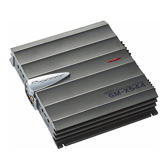
GM-X544
CONTENTS
1. SAFETY INFORMATION............................................2
2. EXPLODED VIEWS AND PARTS LIST ......................2
3. SCHEMATIC DIAGRAM.............................................6
4. PCB CONNECTION DIAGRAM................................12
5. ELECTRICAL PARTS LIST........................................16
PIONEER CORPORATION
PIONEER ELECTRONICS SERVICE INC.
PIONEER EUROPE N.V.
Haven 1087 Keetberglaan 1, 9120 Melsele, Belgium
PIONEER ELECTRONICS ASIACENTRE PTE.LTD. 253 Alexandra Road, #04-01, Singapore 159936
C PIONEER CORPORATION 2000
GM-X644/X1R/UC
X1R/UC,ES
4-1, Meguro 1-Chome, Meguro-ku, Tokyo 153-8654, Japan
P.O.Box 1760, Long Beach, CA 90801-1760 U.S.A.
6. ADJUSTMENT .........................................................20
7. GENERAL INFORMATION.......................................21
7.1 DISASSEMBLY ..................................................21
8. OPERATIONS AND SPECIFICATIONS ....................22
K-ZZA. FEB. 2000 Printed in Japan
ORDER NO.
CRT2479
X1R/UC,EW
Advertisement
Table of Contents

Related Manuals for Pioneer GM-X644


Summary of Contents for Pioneer GM-X644
-
Page 1: Table Of Contents
PIONEER ELECTRONICS SERVICE INC. P.O.Box 1760, Long Beach, CA 90801-1760 U.S.A. PIONEER EUROPE N.V. Haven 1087 Keetberglaan 1, 9120 Melsele, Belgium PIONEER ELECTRONICS ASIACENTRE PTE.LTD. 253 Alexandra Road, #04-01, Singapore 159936 C PIONEER CORPORATION 2000 K-ZZA. FEB. 2000 Printed in Japan... -
Page 2: Safety Information
GM-X644,X544 1. SAFETY INFORMATION - GM-X644/X1R/UC, GM-X544/X1R/UC CAUTION This service manual is intended for qualified service technicians; it is not meant for the casual do-it-yourselfer. Qualified technicians have the necessary test equipment and tools, and have been trained to properly and safely repair complex products such as those covered by this manual. - Page 3 GM-X644,X544 NOTE: - Parts marked by “*” are generally unavailable because they are not in our Master Spare Parts List. - Screws adjacent to ∇ mark on the product are used for disassembly. - PACKING SECTION PARTS LIST Part No.
- Page 4 GM-X644,X544 2.2 EXTERIOR...
- Page 5 HKB0002 29 Diode(D611) FML22R 15 Pin Jack(CN851) HKB0006 30 Thermistor(TH601, 602) CCX1013 (2) CONTRAST TABLE GM-X644/X1R/UC, EW and GM-X544/X1R/UC, ES are constructed the same except for the following: Part No. Mark No. Description GM-X644/X1R/UC GM-X644/X1R/EW GM-X544/X1R/UC GM-X544/X1R/ES 5 Panel HNB0109...
-
Page 6: Schematic Diagram
GM-X644,X544 3. SCHEMATIC DIAGRAM 3.1 OVERALL CONNECTION DIAGRAM(GUIDE PAGE) Note: When ordering service parts, be sure to refer to “EXPLODED VIEWS AND PARTS LIST” or “ELECTRICAL PARTS LIST”. Large size SCH diagram Guide page Detailed page RCA OUT L GAIN=1... -
Page 7: Amp Unit
GM-X644,X544 AMP UNIT OFF/LPF/HPF GAIN=7-31dB OFF/LPF/HPF /EW, ES > HEK0025 HEK0025 > NOTE : Symbol indicates a resistor. Decimal points for resistor No differentiation is made between chip resistors and and capacitor fixed values discrete resistors. are expressed as : ←... - Page 8 GM-X644,X544...
- Page 9 GM-X644,X544...
- Page 10 GM-X644,X544...
- Page 11 GM-X644,X544...
-
Page 12: Pcb Connection Diagram
GM-X644,X544 4. PCB CONNECTION DIAGRAM 4.1 AMP UNIT NOTE FOR PCB DIAGRAMS 1. The parts mounted on this PCB include all necessary parts for several destination. For further information for respective destinations, be sure to check with the schematic diagram. - Page 13 GM-X644,X544 SIDE A BREM...
- Page 14 GM-X644,X544 AMP UNIT...
- Page 15 GM-X644,X544 SIDE B...
-
Page 16: Electrical Parts List
GM-X644,X544 5. ELECTRICAL PARTS LIST NOTE: - Parts whose parts numbers are omitted are subject to being not supplied. - The part numbers shown below indicate chip components. Chip Resistor RS1/_S___J,RS1/__S___J Chip Capacitor (except for CQS..) CKS.., CCS.., CSZS..=====Circuit Symbol and No.===Part Name Part No. - Page 17 RS1/10S101J Thermistor CCX1013 RS1/10S101J Thermistor CCX1035 RS1/10S222J Switch (OFF, LPF, HPF) CSH1029 RS1/10S222J Switch (OFF, LPF, HPF) CSH1029 RS1/10S222J Switch (BFC) (GM-X644/X1R/EW) HSH-156 RS1/10S222J (BFC)(GM-X544/X1R/ES) RS1/10S153J Slide Switch (4CH†2CH) CSH1042 RS1/10S153J Variable Resistor 20kΩ(E) CCS1266 RS1/10S153J Variable Resistor 20kΩ(E) CCS1266 RS1/10S153J Variable Resistor 10kΩ(A)
- Page 18 RD1/4PU221J RD1/4PU181J RD1/4PU152J RD1/4PU181J RS1/10S101J RD1/4PU181J RS1/10S103J RD1/4PU181J RS1/10S223J RD1/4PU163J RS1/10S202J RD1/4PU163J RS1/10S473J RD1/4PU163J RS1/10S102J RD1/4PU163J RS1/10S153J RD1/4PU121J RD1/4PU105J (GM-X644/X1R/EW, GM-X544/X1R/ES) RD1/4PU121J RS1/10S332J RD1/4PU121J RS1/10S332J RD1/4PU121J RS1/10S472J RD1/4PU102J RS1/10S472J RD1/4PU102J RD1/4PU272J RD1/4PU102J RD1/4PU272J RD1/4PU102J RD1/4PU272J RD1/4PU622J RS1/10S472J RD1/4PU622J RS1/2PMF121J RD1/4PU622J...
- Page 19 GM-X644,X544 =====Circuit Symbol and No.===Part Name Part No. =====Circuit Symbol and No.===Part Name Part No. ------ ------------------------------------------ ------------------------- ------ ------------------------------------------ ------------------------- RD1/4PU153J CAPACITORS RD1/4PU682J RD1/4PU223J CCSQCH470J50 RD1/4PU223J CCSQCH470J50 RD1/4PU223J CCSQCH470J50 CCSQCH470J50 RS1/10S471J CFTLA154J50 RS1/10S471J RS1/10S471J CFTLA154J50 RS1/10S471J CFTLA154J50 RS1/10S223J CFTLA154J50...
-
Page 20: Adjustment
GM-X644,X544 =====Circuit Symbol and No.===Part Name Part No. =====Circuit Symbol and No.===Part Name Part No. ------ ------------------------------------------ ------------------------- ------ ------------------------------------------ ------------------------- CQMA102J50 CKSQYB102K50 CQMA102J50 CKSQYB102K50 CQMA102J50 CFTLA564J50 CMA680J2H CEAS100M16 CMA680J2H CEAS100M16 CMA680J2H CEAS100M16 CMA680J2H CEAS100M16 CMA680J2H CQMA472J50 CMA680J2H CQMA472J50 CMA680J2H... -
Page 21: General Information
GM-X644,X544 7. GENERAL INFORMATION 7.1 DISASSEMBLY Case Removing the Case and the Plate (Fig.1) Remove the six screws. Remove the screw. Remove the three screws. Remove the six screws and then remove the Case. Remove the screw and then remove the Plate. -
Page 22: Operations And Specifications
GM-X644,X544 8. OPERATIONS AND SPECIFICATIONS 8.1 OPERATIONS... - Page 23 GM-X644,X544...
-
Page 24: Connection Diagram
GM-X644,X544 Connection Diagram Fuse (30 A) Special red battery wire [RD-223] (sold separately). After making all other connections at the amplifier, Grommet connect the battery wire terminal of the amplifier to the positive (+) terminal of the battery. Fuse (30 A) Ground wire (black) [RD-223] (sold separately). -
Page 25: Specifications
GM-X644,X544 8.2 SPECIFICATIONS - GM-X644/X1R/UC Power source ......................14.4 V DC (10.8 — 15.1 V allowable) Grounding system ............................Negative type Current consumption ......................32.2 A (at continuous power, 4 Ω) Average current drawn* ......................10.9 A (4 Ω for four channels) 15.9 A (4 Ω... - Page 26 GM-X644,X544 - GM-X644/X1R/EW Power source ......................14.4 V DC (10.8 — 15.1 V allowable) Grounding system ............................Negative type Current consumption ....................32.2 A (at continuous power, 4 Ω) Average current drawn* ...................... 10.9 A (4 Ω for four channels) 15.9 A (4 Ω...
- Page 27 GM-X644,X544 - GM-X544/X1R/UC Power source ......................14.4 V DC (10.8 — 15.1 V allowable) Grounding system ............................Negative type Current consumption ......................32.2 A (at continuous power, 4 Ω) Average current drawn* ......................10.9 A (4 Ω for four channels) 15.9 A (4 Ω...
- Page 28 GM-X644,X544 - GM-X544/X1R/ES Power source ......................14.4 V DC (10.8 — 15.1 V allowable) Grounding system ............................Negative type Current consumption ......................32.2 A (at continuous power, 4 Ω) Average current drawn* ......................10.9 A (4 Ω for four channels) 15.9 A (4 Ω...