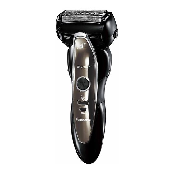
Panasonic ES-ST25 Service Manual
Rechargeable shaver
Hide thumbs
Also See for ES-ST25:
- User manual ,
- Operating instructions manual (278 pages) ,
- Service manual (14 pages)
Advertisement
TABLE OF CONTENTS
1 Warning -------------------------------------------------------------- 2
2 Specifications ----------------------------------------------------- 2
3 Troubleshooting Guide ----------------------------------------- 3
4 Disassembly and Assembly Instructions ---------------- 5
5 Disassembly Instructions ------------------------------------- 8
6 Schematic Diagram ---------------------------------------------12
7 Exploded View and Replacement Parts List -----------13
Model No.
Europe
CIS
Oceania
PAGE
© Panasonic Corporation, 2013.
All rights reserved. Unauthorized copying and distri-
bution is a violation of law.
Order Number SD1305X31CE
Rechargeable Shaver
ES-ST25
PAGE
Advertisement

Summary of Contents for Panasonic ES-ST25
-
Page 1: Table Of Contents
4 Disassembly and Assembly Instructions ---------------- 5 5 Disassembly Instructions ------------------------------------- 8 6 Schematic Diagram ---------------------------------------------12 7 Exploded View and Replacement Parts List -----------13 © Panasonic Corporation, 2013. All rights reserved. Unauthorized copying and distri- bution is a violation of law. -
Page 2: Warning
1 Warning Caution: • Pb free solder has a higher melting point that standard solder; Typically the melting point is 50 - 70°F (30 - 40°C) higher. Please use a soldering iron with temperature control and adjust it to 750 ± 20°F (400 ± 10°C). In case of using high temperature solder- ing iron, please be careful not to heat too long. -
Page 3: Troubleshooting Guide
3 Troubleshooting Guide 3.1. Main unit and charging adaptor... -
Page 5: Disassembly And Assembly Instructions
4 Disassembly and Assembly Instructions Follow the procedure below to disassemble the main unit. 1. Remove the cap, the outer foil with foil frame and the inner blades. 2. Loosen one screw and take out the bottom cover. 3. Take out the screw caps and rear panel. 4. - Page 6 6. Remove the trimmer driving bar or the slit blade driving bar with pressing bars outward. NOTE: Driving bars replacement is required only when replacing the linear motor assembly. 7. Remove the module and chassis assembly from the housing A. 8.
- Page 7 9. Remove the battery from the chassis. 10. Remove the linear motor assembly from the hosing A. 11. Unsolder the lead wires.
-
Page 8: Disassembly Instructions
5 Disassembly Instructions NOTE: When reassembling, replace the new waterproof rubber. Make sure whether there is NO foreign substance sticking around a part covered with water seal. 1. Solder the lead wires. NOTE: Make sure of the polarity. NOTE: Use lead-free solder. Set the temperature of solder- ing iron between 350-380°C and touch within three seconds. - Page 9 4. Before assembling the linear motor assembly to the hous- ing A, attach the cleaning shutter from the bottom side. 5. Slid up the cleaning shutter and confirm whether two hooks are assembled firmly. 6. Assemble the battery and chassis block into the housing. NOTE: Make sure not to scratch or deform the module.
- Page 10 7. Insert the rechargeable battery into chassis. Confirm the direction of battery. Once battery is disassembled, the battery is reset. Connect the battery with the charging adaptor about 10 seconds first. 8. Place the wire as shown the figure. NOTE: Press fit the lead wire neatly to avoid any pinching.
- Page 11 12. Tighten six screws and attach the screw caps. 13. Attach the rear panel with care of hooks. 14. Tighten a screw with the bottom cover.
-
Page 12: Schematic Diagram
6 Schematic Diagram... -
Page 13: Exploded View And Replacement Parts List
7 Exploded View and Replacement Parts List 7.1. Exploded View... - Page 14 7.2. Replacement Prarts List Safety Ref.No. Part No. Part Name & Descriptions Quantity Remarks WESST23X7158 PROTECTIVE CAP WESST23K0007 OUTER FOIL FRAME WES9087Y OUTER FOIL WES9068Y INNER BLADE WES8176L1077 SLIT BLADE DRIVING BAR WES8119L1087 TRIMMER DRIVING BAR WESST23L0587 STOPPER WES8176L6007 P TIGHT SCREW M2-12 WESST23L0207 RETAINING PLATE...


