
Related Manuals for Siemens FDCW241


Summary of Contents for Siemens FDCW241
- Page 1 FDCW241 Radio gateway Technical Manual Building Technologies A6V10227639_e_en_-- 2013-09-01 Control Products and Systems...
-
Page 2: Legal Notice
Legal notice Technical specifications and availability subject to change without notice. © 2011-2013 Copyright by Siemens Switzerland Ltd Transmittal, reproduction, dissemination and/or editing of this document as well as utilization of its contents and communication thereof to others without express authorization are prohibited. -
Page 3: Table Of Contents
Table of contents About this document ..................5 Applicable documents ..................7 Technical terms ....................7 History of changes ....................8 Safety ......................9 Safety instructions ....................9 Safety regulations for the method of operation ..........11 Standards and directives complied with ............13 Release Notes ....................13 Structure and function ................. - Page 4 7.4.5 Connecting the radio cell to the detector line ........46 Replacing the radio gateway ................46 7.5.1 Replacing the radio gateway FDCW241 ........... 47 Firmware update .................... 49 7.6.1 Updating the firmware of the radio gateway ........49 Basic principles for replacing the battery pack ..........50 Replacing the batter pack on the radio gateway ..........
-
Page 5: About This Document
About this document Applicable documents 1 About this document Goal and purpose This document contains information on the radio gateway FDCW241. Following the instructions consistently will ensure that the product can be used safely and without any problems. Target groups... - Page 6 About this document Applicable documents Document identification The document ID is structured as follows: ID code Examples ID_ModificationIndex_Language_COUNTRY A6V10215123_a_de_DE -- = multilingual or international A6V10215123_a_en_-- A6V10315123_a_--_-- Date format The date format in the document corresponds to the recommendation of international standard ISO 8601 (format YYYY-MM-DD). Conventions for text marking Markups Special markups are shown in this document as follows:...
-
Page 7: Applicable Documents
About this document Applicable documents 1.1 Applicable documents Document ID Title 001508 Guidelines Connection factors, line resistances and capacitances for fire detection systems collective, AnalogPLUS, interactive, FDnet 008250 Operation Line tester FDUL221 008331 List of compatibility (for 'Sinteso™' product line) 009052 FS20 Fire detection system - Commissioning, Maintenance, Troubleshooting... -
Page 8: History Of Changes
About this document History of changes 1.3 History of changes The reference document's modification index applies to all languages into which the reference document is translated. The first edition of a language version or a country variant may, for example, have the modification index 'd' instead of 'a' if the reference document already has this modification index. -
Page 9: Safety
Safety Safety instructions 2 Safety 2.1 Safety instructions The safety notices must be observed in order to protect people and property. The safety notices in this document contain the following elements: Symbol for danger Signal word Nature and origin of the danger Consequences if the danger occurs Measures or prohibitions for danger avoidance Symbol for danger... - Page 10 Safety Safety instructions How risk of injury is presented Information about the risk of injury is shown as follows: WARNING Nature and origin of the danger Consequences if the danger occurs Measures / prohibitions for danger avoidance How possible damage to property is presented Information about possible damage to property is shown as follows: NOTICE Nature and origin of the danger...
-
Page 11: Safety Regulations For The Method Of Operation
2.2 Safety regulations for the method of operation National standards, regulations and legislation Siemens products are developed and produced in compliance with the relevant European and international safety standards. Should additional national or local safety standards or legislation concerning the planning, assembly, installation,... - Page 12 Disregard of the safety regulations Before they are delivered, Siemens products are tested to ensure they function correctly when used properly. Siemens disclaims all liability for damage or injuries caused by the incorrect application of the instructions or the disregard of danger warnings contained in the documentation.
-
Page 13: Standards And Directives Complied With
Safety Standards and directives complied with 2.3 Standards and directives complied with A list of the standards and directives complied with is available from your Siemens contact. 2.4 Release Notes Limitations to the configuration or use of devices in a fire detection installation with a particular firmware version are possible. -
Page 14: Structure And Function
Observe the country-specific regulations relating to the permitted number of devices. The radio gateway always occupies two addresses. You will find the performance characteristics in documents A6V10227631 and A6V10271323. [ The radio gateway FDCW241 can communicate with the following devices: Radio fire detector FDOOT271 Radio manual call point FDM273... -
Page 15: External View
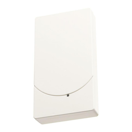
Structure and function Setup Radio gateway FDCW241 on detector line Radio cell 4 Radio gateway FDCW241 Radio fire detector FDOOT271 5 Detector line Radio manual call point FDM273 6 Radio cell overlapping 3.1.2 External view External view of radio gateway FDCW241... -
Page 16: Internal View
Structure and function Setup 3.1.3 Internal view H2 H3 H4 H5 Internal view of radio gateway FDCW241 1 Detector line terminal strip 10 Cable entries 2 2-pin terminal strip 11 Fastening tabs for strain relief 3 Aerial H1 Red / green LED for detector line... -
Page 17: Scope Of Delivery
Structure and function Function 3.1.4 Scope of delivery 1x radio gateway FDCW241 1x screw for cover 2x cable ties (2.4 x 102 mm) for cable strain relief Batteries are not included in the scope of delivery. A battery pack is always needed to commission and operate the radio gateway. -
Page 18: Behavior In Degraded Mode
Structure and function Function 3.2.2 Behavior in degraded mode Applicable for the FDnet/C-NET: When the main processor of the fire control panel fails, the control panel is in degraded mode operation. Depending on the control panel type, the fire control panel can continue to perform the most important alarming and signaling functions in degraded mode operation. - Page 19 Structure and function Function Red / green LED for detector line Yellow LED for maintenance mode Yellow LED for reset Yellow LED for the radio network Yellow LED for the charge status of the battery pack Display Meaning H1, H2, H3, H4, H5 When a power supply is present, the radio gateway operates without any problems.
-
Page 20: Power Supply
Flashes yellow 'Battery empty' Interval: 0.5 The battery pack is missing or not connected. seconds Status of radio gateway FDCW241 3.3 Power supply Power supply via the detector line For normal operation Power supply from battery pack BAT3.6-10 When the battery pack is supplying power, the radio network remains active even if the detector line is switched off. -
Page 21: Accessories
BAT3.6-10 LI-SOCl2 battery pack 3.6 V, 10 Ah Batteries with battery cable Battery connector with protection against polarity reversal Inscription field for commissioning date Compatible with: – Radio gateway FDCW241 – Radio manual call point FDM273 – Radio manual call point FDM275 – Radio fire detector FDOOT271 Order no.: S54370-Z11-A1... -
Page 22: Mcl-Usb (Radio) Adapter Fduz227
Interface converter for USB on MC link Compatible with: – Floor repeater terminal FT2010 – Floor repeater display FT2011 – Radio gateway FDCW221 and FDCW241 – Detector exchanger and tester FDUD292 – Intelligent detector tester FDUD293 – Line tester FDUL221 –... -
Page 23: Planning
– = not compatible You will find details in the 'List of compatibility'. Limitations Maximum 16 FDCW241 radio gateways per line Reduced if length of line is over 2,200 m as per Sinteso Quantities tool (A6V10094878) or Cerberus PRO Quantities tool (A6V10211118) -
Page 24: Mounting/Installation
Mounting/Installation Installation 5 Mounting/Installation 5.1 Installation 89 mm 167 mm 28 mm 142-147 mm 1 1 1 3 1 1 1 4 1 1 1 5 Installing the radio gateway 1 Screw 2 Mounting points 3 Mounting point for installation in housing FDCH221 4 Cable entries 5 Strain relief fastenings You have the radio gateway, battery pack, fixing screws, and cable tie to hand. - Page 25 Mounting/Installation Installation Openings in the supporting surface for recess-mounted cables. Openings in the narrow side for surface-mounted cables. 5. Insert the cables into the back box. 6. Install the back box, without the battery pack, on a flat surface using two screws (Ø...
-
Page 26: Installation In Housing Fdch221
Mounting/Installation Installation in housing FDCH221 5.2 Installation in housing FDCH221 The radio gateway can be installed in a separate housing FDCH221. The housing protects the radio gateway from dirt and dust. Ø max. 4.8 mm Installing housing FDCH221 Cable entry Screws for securing the housing Cables Screws for housing cover... -
Page 27: Connecting The Radio Gateway
Connections on the radio gateway FDCW241 detector line terminal strip The radio gateway 'FDCW241' automatically assigns the additional, virtual address 'FDCL221v' as a line separator. When you assign the connections, you determine the order in which the devices are read in at the control panel. - Page 28 Mounting/Installation Connecting the radio gateway Radio cell as LOOP FC20xx FC720x LOOP1_2- LOOP1_2+ LOOP1_1- LOOP1_1+ FC20xx FC720x LOOP1_2- LOOP1_2+ LOOP1_1- LOOP1_1+ Loop connection Radio cell as stub Stub connection only Building Technologies A6V10227639_e_en_-- Fire Safety 2013-09-01...
-
Page 29: Wiring Connections
Mounting/Installation Connecting the radio gateway Radio cell as sub-stub on loop Sub-stub on loop connection Wiring connections NOTICE Failure of the electrical connection Damage to the screw terminals or contact problems may lead to faults in the electrical connection. If the cable cross-sections you want to connect to the radio gateway are larger than 1.5 mm², the screw terminals may be damaged or contact problems may arise. -
Page 30: Commissioning
Commissioning Basic rules for commissioning 6 Commissioning The procedure for commissioning via the control panel is no different to the one used for commissioning wired devices. The relevant fire detection system documents also apply to the SWING radio fire detection system. There are two operating conditions for radio cells. -
Page 31: Commissioning The Radio Cell
Commissioning Commissioning the radio cell 6.2 Commissioning the radio cell The radio gateway forms a radio cell with the radio devices that are connected. The radio cell is switched to maintenance mode along with the radio gateway. To ensure that radio devices are integrated into the correct radio cell, only one radio cell may be in maintenance mode at any given time. - Page 32 Commissioning Commissioning the radio cell The radio gateway is installed. The radio gateway is not connected to the detector line. The terminal strips of the detector line have been wired in accordance with the required topology. The user is familiar with the content of chapter 'Change and extend the detector line' of the control panel documentation.
- Page 33 Use line tester FDUL221. Make sure that the radio gateway is displayed with two addresses, as FDCL221v and as FDCW241. Check that the internal alarm indicators of all the radio devices are off. The radio cell is complete and the radio devices are logged on.
-
Page 34: Maintenance / Troubleshooting
Maintenance / troubleshooting Establishing factory settings 7 Maintenance / troubleshooting Maintenance work on a radio cell covers: Adding radio devices Removing radio devices Replacing the battery pack Requirements for performing maintenance on a radio cell: The radio gateway has been switched to 'maintenance mode' The relevant zone has been switched off at the control panel You will find more information in the 'Change and extend the detector line' chapters of the following documents:... - Page 35 Maintenance / troubleshooting Establishing factory settings Proceed as follows to restore the radio gateway to the factory settings: The radio gateway must not be connected to the detector line. 1. Release the battery connector (1) to interrupt the power supply. 2.
-
Page 36: Putting The Radio Cell Into Maintenance Mode
Maintenance / troubleshooting Putting the radio cell into maintenance mode 7.2 Putting the radio cell into maintenance mode Radio gateway FDCW221 Yellow LED for maintenance mode Button for maintenance mode The housing for the radio gateway is open. The radio gateway is in normal operation. 1. -
Page 37: Putting The Radio Cell Into Normal Operation
Maintenance / troubleshooting Putting the radio cell into normal operation 7.3 Putting the radio cell into normal operation Radio gateway FDCW221 Yellow LED for maintenance mode Button for maintenance mode The housing for the radio gateway is open. The process of logging radio devices on to the radio gateway is complete. 1. -
Page 38: Adding Or Removing Radio Devices
Maintenance / troubleshooting Adding or removing radio devices 7.4 Adding or removing radio devices The procedure for adding or removing radio devices on a detector line is no different to the one used for adding or removing wired devices. The relevant fire detection system documents also apply to the SWING radio fire detection system. - Page 39 Maintenance / troubleshooting Adding or removing radio devices Yellow LED for maintenance S1 Button for maintenance mode mode Yellow LED for power supply S2 Reset button and reset Yellow LED for radio network You have the new radio device and its battery pack to hand. You have a device location plan showing the locations of the radio devices in the radio cell.
- Page 40 Maintenance / troubleshooting Adding or removing radio devices 9. Finish the process of logging the radio devices on to the radio gateway. Check that the process of logging on to the radio gateway is complete. Wait until LED (H4) on the radio gateway goes out. Check that the number of logged-on radio devices in the radio cell is complete.
-
Page 41: Removing Radio Devices Temporarily
Maintenance / troubleshooting Adding or removing radio devices 7.4.2 Removing radio devices temporarily An individual radio device may be removed temporarily, for example, if renovation work is being carried out. WARNING Risk of injury due to undetected fire When parts of the system are switched off, they are not monitored and no fire alarm signals are issued for them. -
Page 42: Removing Radio Devices Permanently
Maintenance / troubleshooting Adding or removing radio devices 7.4.3 Removing radio devices permanently The procedure for removing radio devices on a detector line is no different to the one used for removing wired devices. The relevant fire detection system documents also apply to the SWING radio fire detection system. When radio devices are removed permanently, the radio cell changes. - Page 43 Maintenance / troubleshooting Adding or removing radio devices Proceed as follows to remove a radio device: You have a device location plan showing the locations of the radio devices in the radio cell. It is possible to access the station. 1.
-
Page 44: Replacing A Radio Device With Another Of The Same Type
Maintenance / troubleshooting Adding or removing radio devices 7.4.4 Replacing a radio device with another of the same type The procedure for replacing radio devices on a detector line is no different to the one used for replacing wired devices. The relevant fire detection system documents also apply to the SWING radio fire detection system. - Page 45 Maintenance / troubleshooting Adding or removing radio devices Proceed as follows to replace the radio device: The housing for the radio gateway is open. 1. Proceed according to chapter 'Changing and extending the detector line' in the control panel documentation. Document 009052 applies to control panels FC20xx.
-
Page 46: Connecting The Radio Cell To The Detector Line
Maintenance / troubleshooting Replacing the radio gateway 13. Press and hold button (S1) for at least 2 seconds. The radio cell is in normal operation. The radio gateway deletes the old radio device from its memory. 14. Close the radio gateway housing. 15. -
Page 47: Replacing The Radio Gateway Fdcw241
4. Using the 'FXS2061 SWING tool' software, select the relevant radio gateway in the main menu Network. 5. Select the 'Update' command from the 'Exchange FDCW241' menu bar. 6. Enter your password. The initial password is '1234'. 7. Follow the instructions exactly as they are shown in the window. - Page 48 Maintenance / troubleshooting Replacing the radio gateway 11. The new radio gateway automatically has the net ID of the old radio gateway. 12. Check whether the LED (H4) is flashing. 13. Overwrite the net ID of the new radio gateway with the net ID of the old radio gateway on the type plate.
-
Page 49: Firmware Update
The firmware update is in a ZIP file. The DSV file version and the firmware version must be compatible. 1. Select the relevant Network radio gateway in the 'FDCW241' menu bar. 2. Select the 'Update' menu in the 'Update FDCW241' menu bar. -
Page 50: Basic Principles For Replacing The Battery Pack
Maintenance / troubleshooting Basic principles for replacing the battery pack 7.7 Basic principles for replacing the battery pack CAUTION Risk of explosion due to fire or short-circuit, even if the battery pack is empty Injuries caused by flying parts To prevent the connection wires short-circuiting, insulate the connections and stick the battery cable to the battery pack. -
Page 51: Replacing The Batter Pack On The Radio Gateway
The control panel signals a battery fault for the radio gateway. LED (H1) flashes and LED (H5) flashes at 2-second intervals. If the battery has failed completely, LED (H5) flashes quickly (twice per second). Radio gateway FDCW241 with battery pack inserted Holder for battery pack 4 Battery cable Battery pack... - Page 52 Maintenance / troubleshooting Replacing the batter pack on the radio gateway 5. Label the new battery pack with the current date (on the inscription field). 6. Wait until the control panel shows 'BATTERY MISSING' after 5…10 seconds. 7. Insert the new battery pack (2). Make sure that it latches into the holders correctly.
-
Page 53: Specifications
Specifications Technical data 8 Specifications Unless otherwise mentioned, the following data applies: Temperature = 25 °C Air pressure = 1000 hPa (750 Torr) You will find information on approvals on the data sheet for the device. See also Applicable documents [ 8.1 Technical data Detector line Operating voltage... - Page 54 Specifications Technical data Radio Max. 16 Number of radio gateways with radio cell overlapping Max. 30 Number of radio devices per radio gateway as loop Max. 30 Number of radio devices per radio gateway as stub Sending/receiving aerials Dual band aerial Radio transmission: Frequency range 868…870 MHz SRD band...
- Page 55 Housing material Polycarbonate (PC) Makrolon 9125 Color RAL 9010 white Standards European standards EN 54-17 EN 54-18 EN 54-25 EN 300220-2 EN 301489-3 EN 60950 International standards ISO 9001 ISO 9004 Siemens standards SN 36350 Building Technologies A6V10227639_e_en_-- Fire Safety 2013-09-01...
-
Page 56: Dimensions
Specifications Dimensions 8.2 Dimensions Radio gateway FDCW241 89 mm 167 mm 28 mm 8.3 Environmental compatibility and disposal This device is manufactured using materials and procedures which comply with current environmental protection standards as best as possible. More specifically, the following measures have been... -
Page 57: Glossary
Glossary Glossary Radio cell Unit comprising all radio devices connected to the radio gateway Radio device Any device that the radio gateway monitors Radio network Within a radio cell, bidirectional radio connections are established between the radio devices. Together with the radio gateway connections, these create a radio network. -
Page 58: Index
Position in gateway, 16 Replacement for radio gateway, 51 Radio gateway Replacing the battery pack, 50 Firmware update, 49 Radio gateway FDCW221 Replacing the radio gateway FDCW241, 47 Cable cross-section, 29 Recycling, 56 Collective behavior Degraded mode operation, 18 Compatibility, 23... - Page 59 Index Building Technologies A6V10227639_e_en_-- Fire Safety 2013-09-01...
- Page 60 Issued by © 2011-2013 Copyright Siemens Switzerland Ltd Siemens Switzerland Ltd Technical specifications and availability subject to change without notice. Infrastructure & Cities Sector Building Technologies Division International Headquarters Gubelstrasse 22 CH-6301 Zug Tel. +41 41-724 24 24 www.siemens.com/buildingtechnologies Document ID...